Exercise 03 - Computer-Controlled Cutting
Make laser cutter test part(s), varying cutting settings and slot dimensions
Design make, and document a parametric press-fit construction kit, accounting for the lasercutter kerf, which can be assembled in multiple ways
Lesson at Opendot
Enrico Bassi gave us a lesson about laser cutting on Thursday afternoon. He showed how a laser cutting is working through the lens, the laser beam and the function of the air flow. We discuss better what is kerf and how to manage it in our press-fit models.
We checked several press-fit connections. We discuss about wood sheet material and some tips to avoid cracks in the sharp corners.
We checked some useful references: Makercase a web page to make parametric boxes, Pepakura to do 3D shapes through 2D paper sheets.
Finally he showed how to manage layers, colors on the software of the laser cutter and how to use vinylcutter here in Opendot. After we did some cuttings all together.
Individual laser cutter test(s)
First test
At the very beginning my issue was to figure out how to get to a drawing that was cuttable by the machine, starting from a drawing that was parametric.
Considering the limited resources of my old lap top, I had to avoid Solidworks, Autodesk and Freecad, see exercise 02 for a better explanation. The remaining softwares were Onshape and Antimony.
I activated Onshape with an educational id and I followed some tutorials. The software is able to export in dwg format so it would be capable to comunicate with the laser cutter in Opendot. But I thought that was not a good idea to start from zero with a new software.
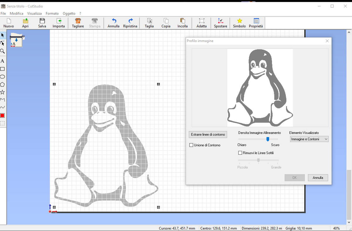
At this point Enrico Bassi remembered me that png files are capable to be transformed to vector files on Inkscape. That was my turning point. I downloaded the example file joints.sb from the class page and I began to play with the models in Antimony.
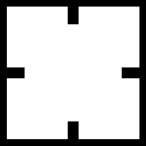
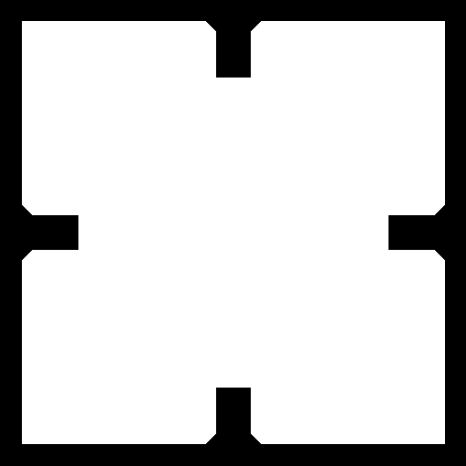
Antimony can export in .stl and .png in my understanding. Below my first png file exported with Antimony.
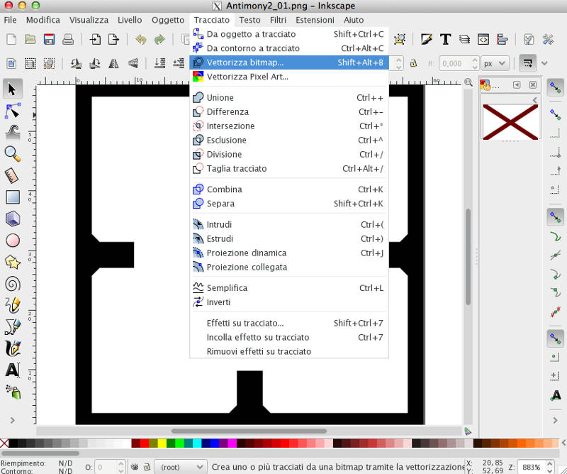
I opened it in Inkscape and I trasformed it in a vector path.
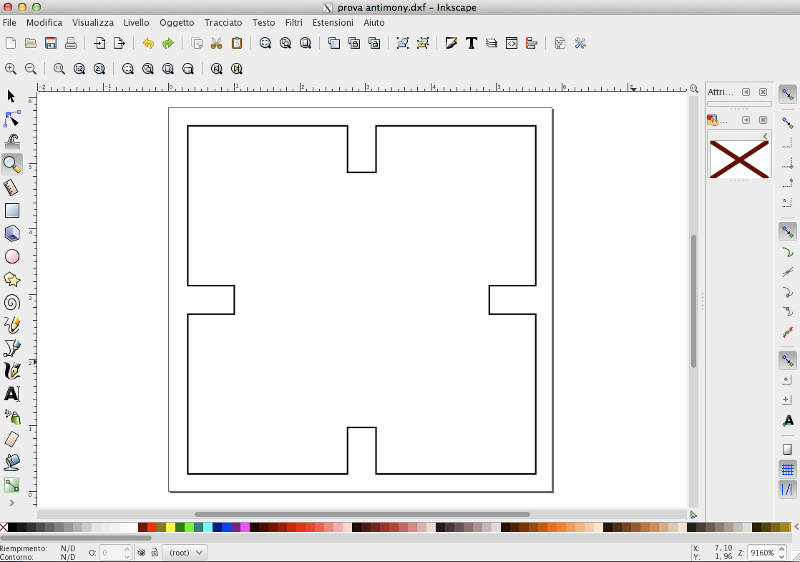
From Inkscape I exported the file in .dxf format that is readable by Rhinoceros, which is the software commonly used at Opendot to laser cutting. I scaled the image paying not too much attention to the thickness of the sheet that I would used, big mistake!
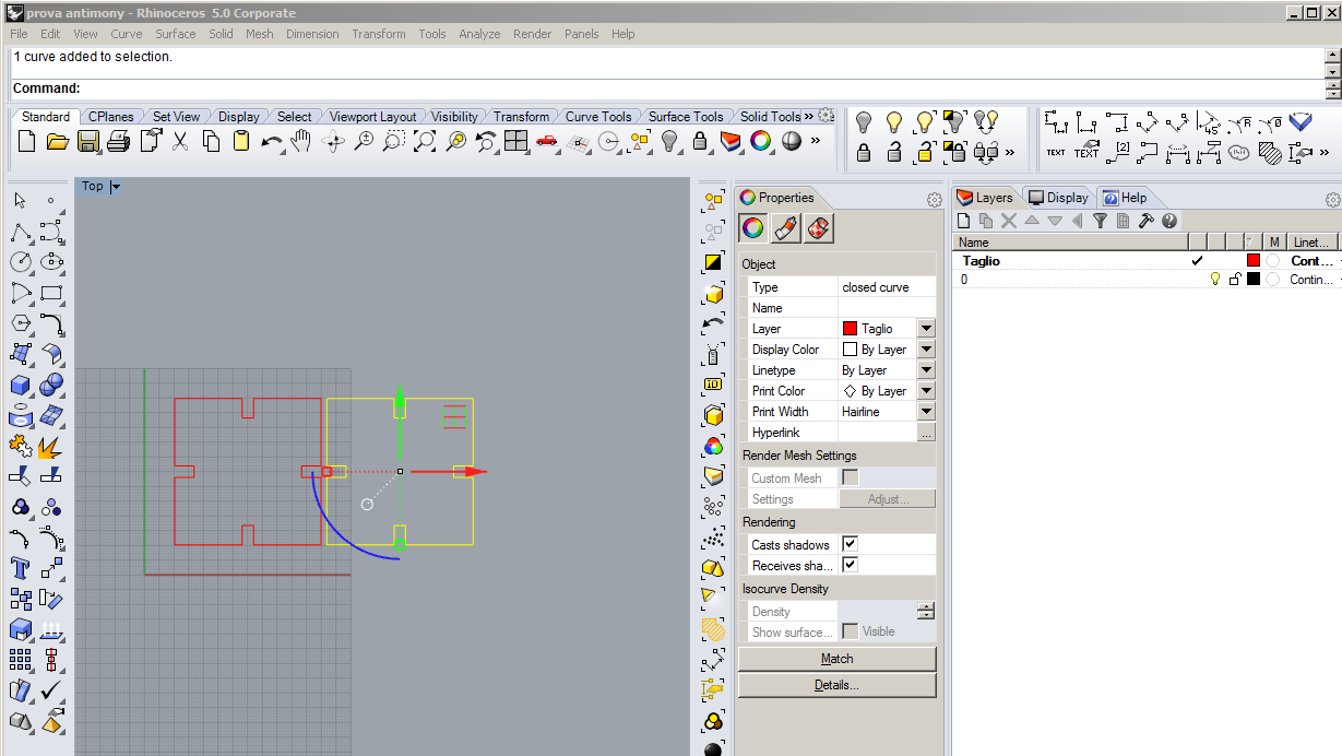
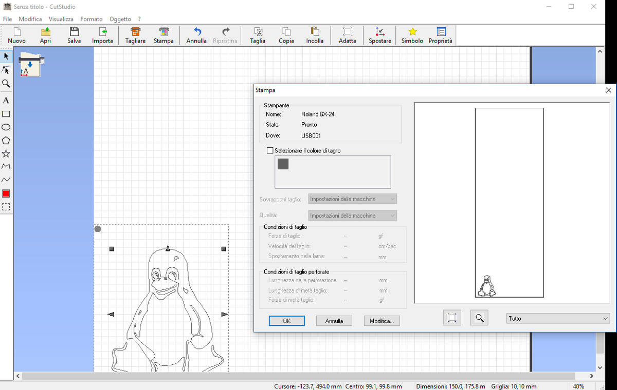
I put the drawing on a new layer 'Taglio' with red color and I set the print width Hairline which is the only one that is cut by the laser cutter.
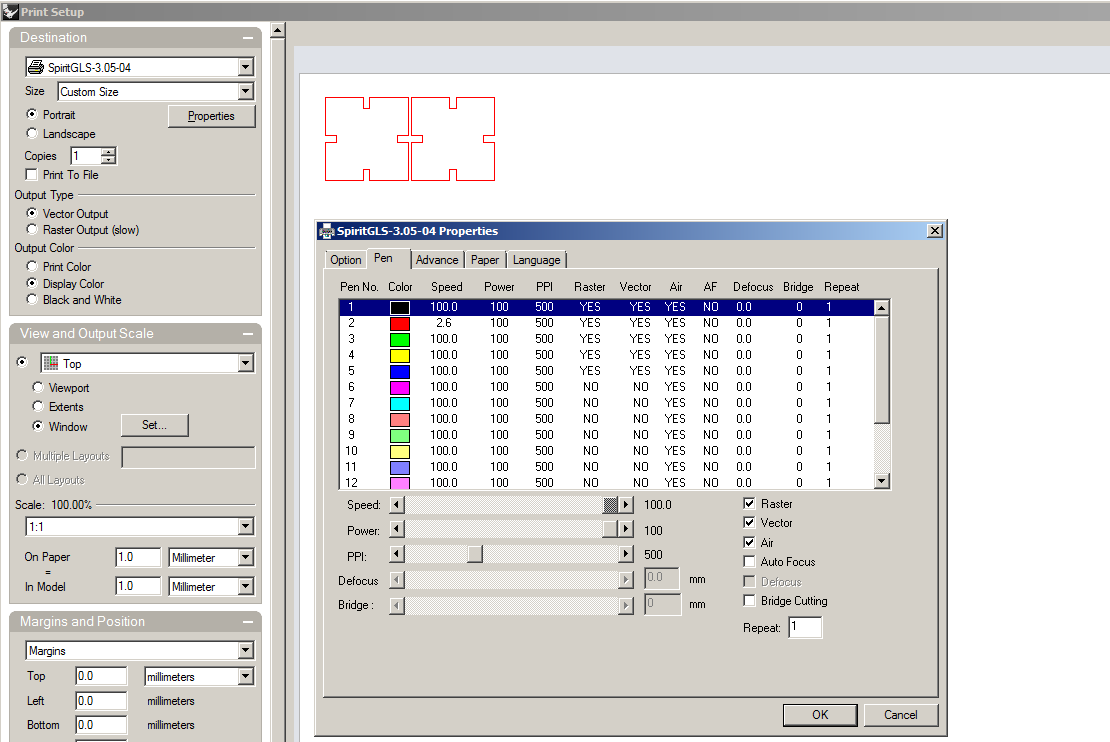
I opened the print setup and then in the printer properties I set the red color pen with 100% of power and 2,6 of speed, which are the standard settings to cut 3mm playwood. I moved the page matching the position of the wood piece in the laser cutter.
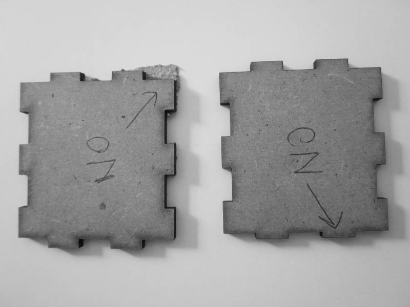
Second test
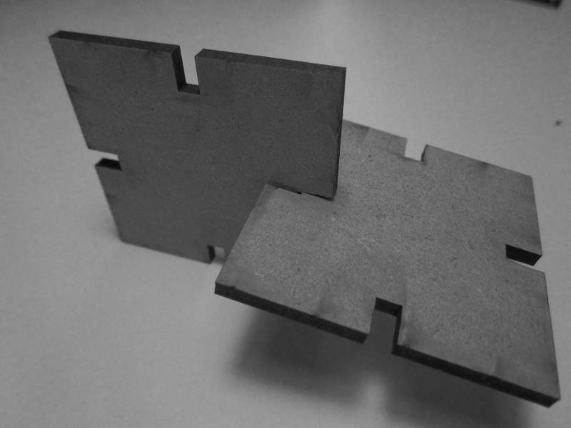
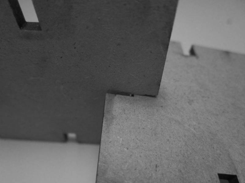
This time I chose a shape whith champfer on the corners of the fits.
I considered a total kerf of 0,2mm and with the thickness of the material of 3mm, I set the fits to 2,9mm of width.
The result was good!
Resuming my workflow for laser cutting:
- Antimony: parametric modelling --> .png file
- .png --> Inkscape: transform bitmap to vector path --> .dxf file
- .dxf --> Rhinoceros: check dimensions and set printing settings --> laser cutter
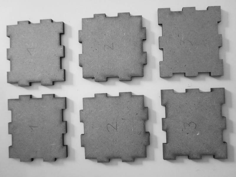
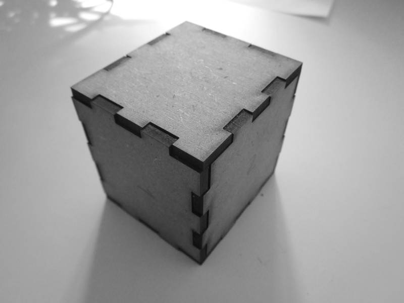
Parametric press-fit boxes
Time is precious during the Fab Academy, especially when you are working at the same time in a private company. So my idea was to do a parametric press-fit kit that was in some way usable to my final project.
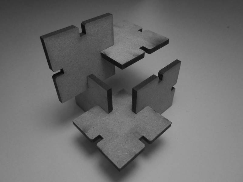
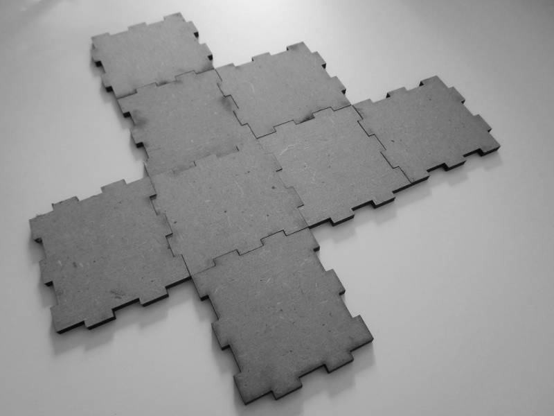
I thought to do a parametric press-fit box, which could be a small prototype of the structure of my final project and in any case learn how to do boxes would be useful.
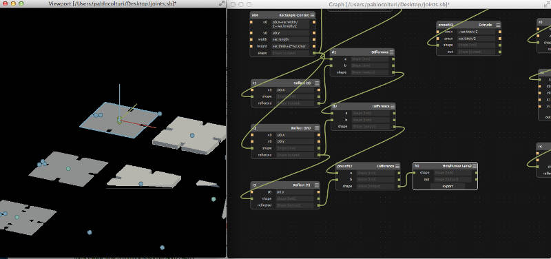
The software I emploied was again Antimony. I read the tutorial Antimony Tabs to better understand how to parametric modelling with this software, which I really recommend for 2D parametric, especially if you love to do simple maths and if your lap top is a very old Macbook pro as mine.
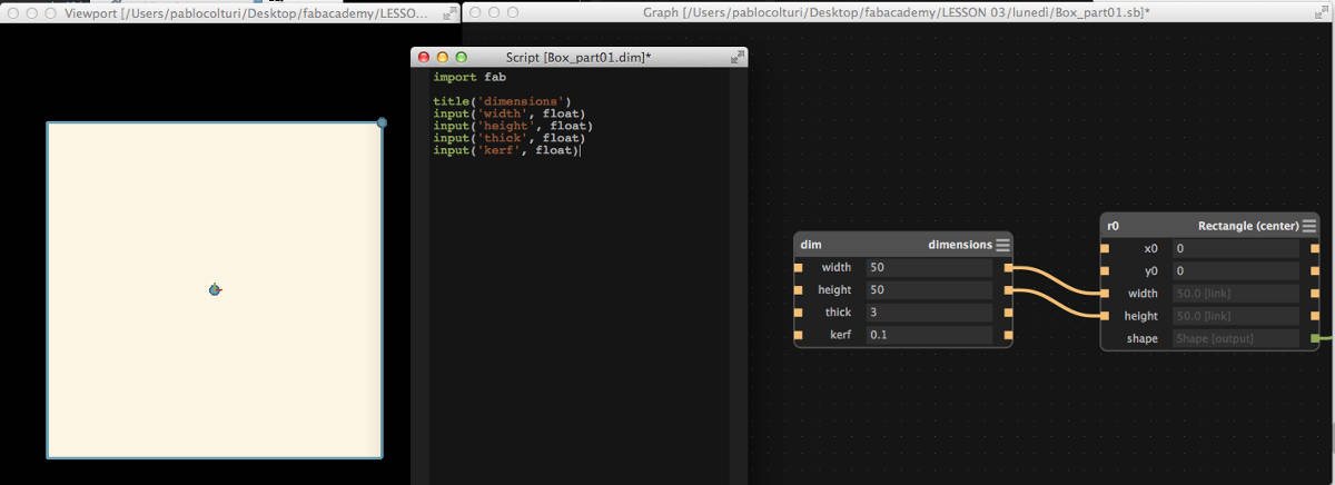
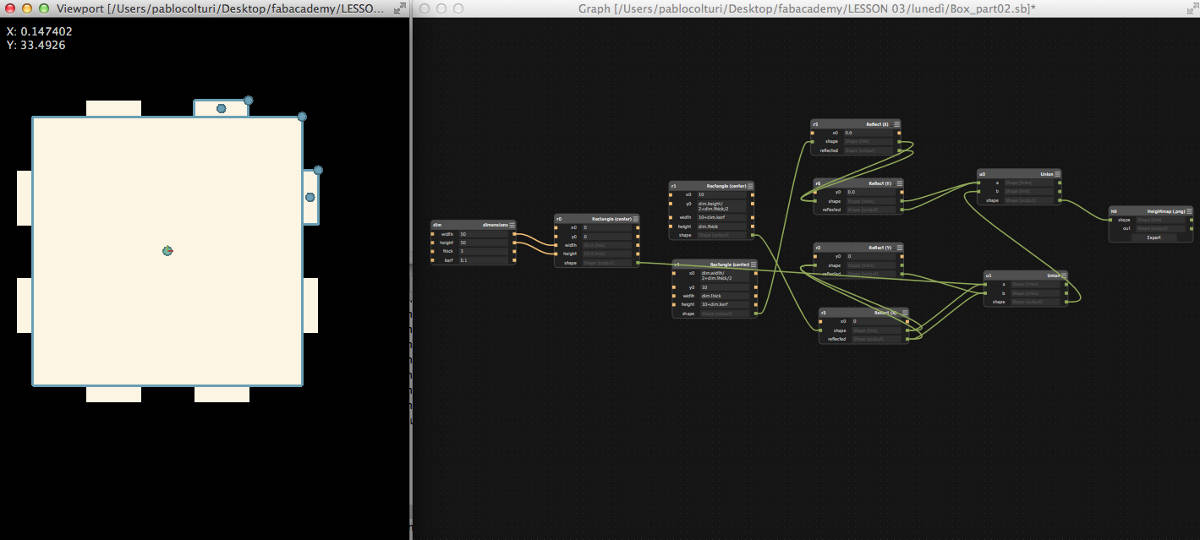
Following the tutorial above mentioned, I started with a rectangular shape and a script node with dimension, thickness of the material. I did a personal version adding a new parameter in order to control the kerf of the laser cut.
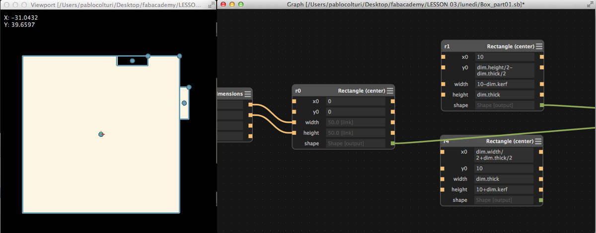
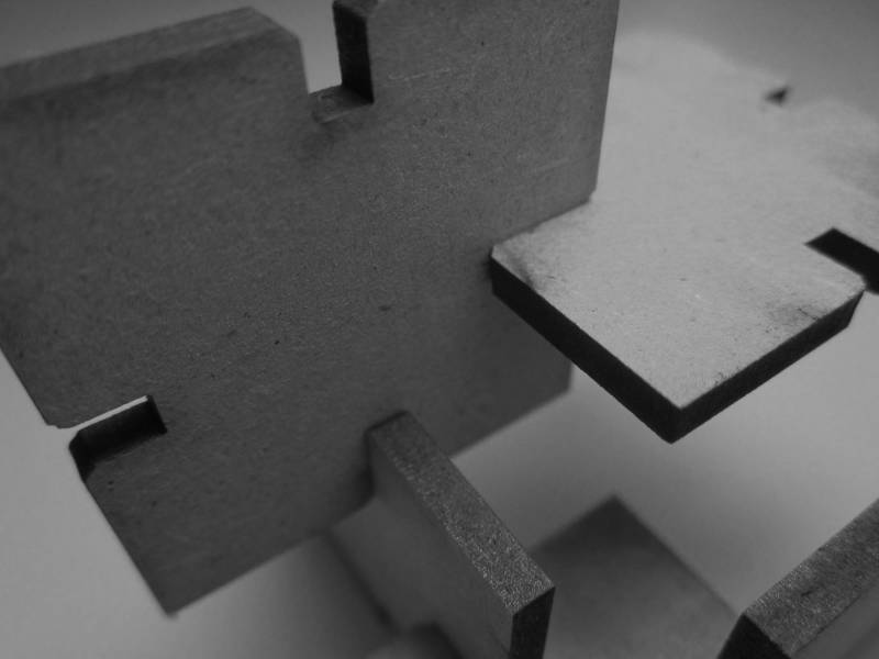
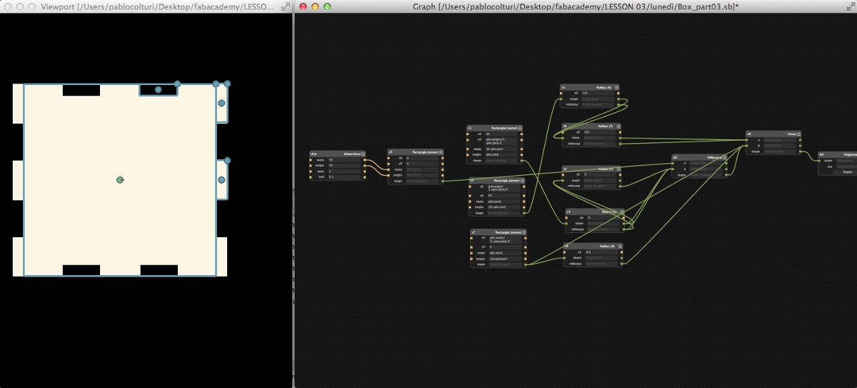
Next I added two rectangles to make the tooths and the slots. I tried to do everything I could parametric. So if I have to change the thicknes or the kerf everything update automatically.
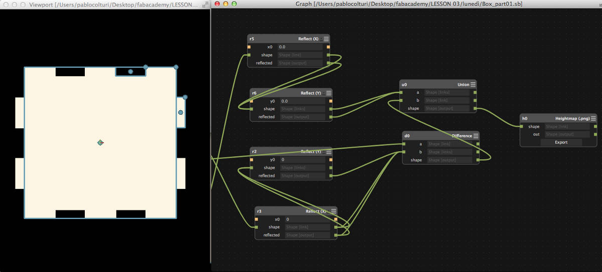
Some reflect node to finish and the export node to get the png image that will be vectorialized in Ikscape.
Computer-controlled cutting in my final project
Please check the page Final Project - 03 Mechanics for more documentation about laser cutting.
Cut something on the vinylcutter
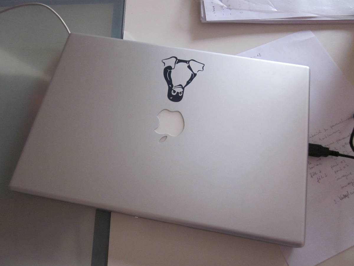
This week I have got familiar also with the vynilcutter. I did a first cut together with my colleagues of the Fab Academy and then I tried to make it by myself.
It is very easy and fun to make stickers with the vynilcutter. I will make soon a few more for my friends and family.