Exercise 09, 11 - Mechanical design, Machine Design
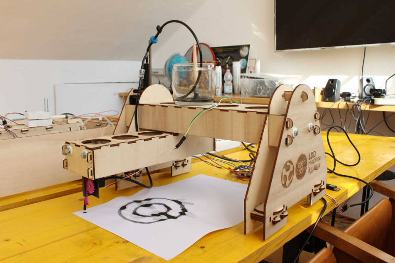
Make a machine, including the end effector, build the passive parts and operate it manually.
Automate your machine, document the group project and the individual contribution.
References
I started the assigment studying and searching for some good references. I found this and this pages with the modular machines made by Nadya Peek and James Coleman at the MIT.

Then I had a look to the past machines made here in Opendot during Fab Academy 2016 at this page.
Below one example:
Sketches and measures of mechanical parts
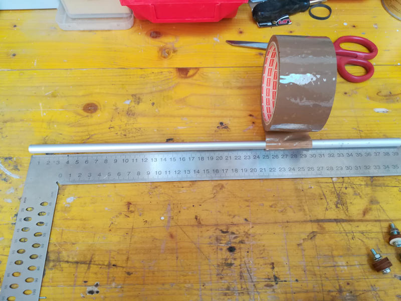
We dismantled an older machine in oreder to reuse some mechanical parts, in particular some rods and some stepper motor with endless screws plus bolts and other mechanical parts.
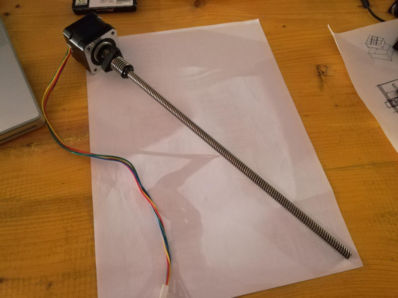
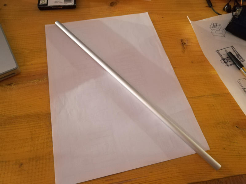
I take measures of that mechanical parts.
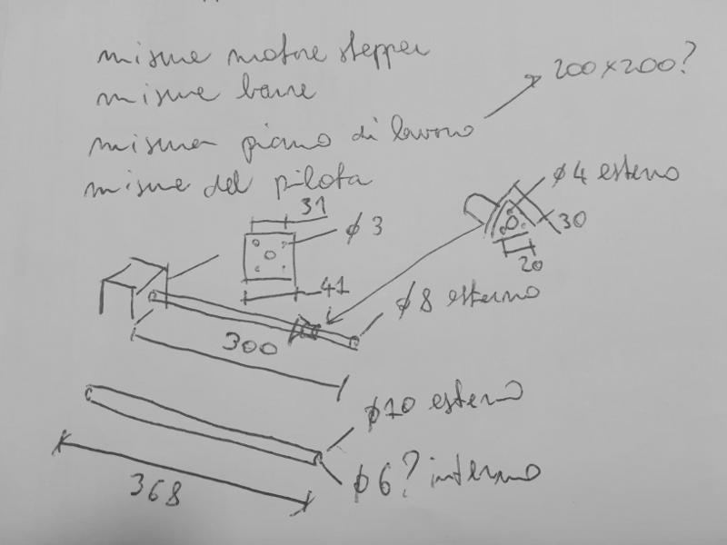
I did some sketches of the mechanical layout of the machine with 2 linear axes.
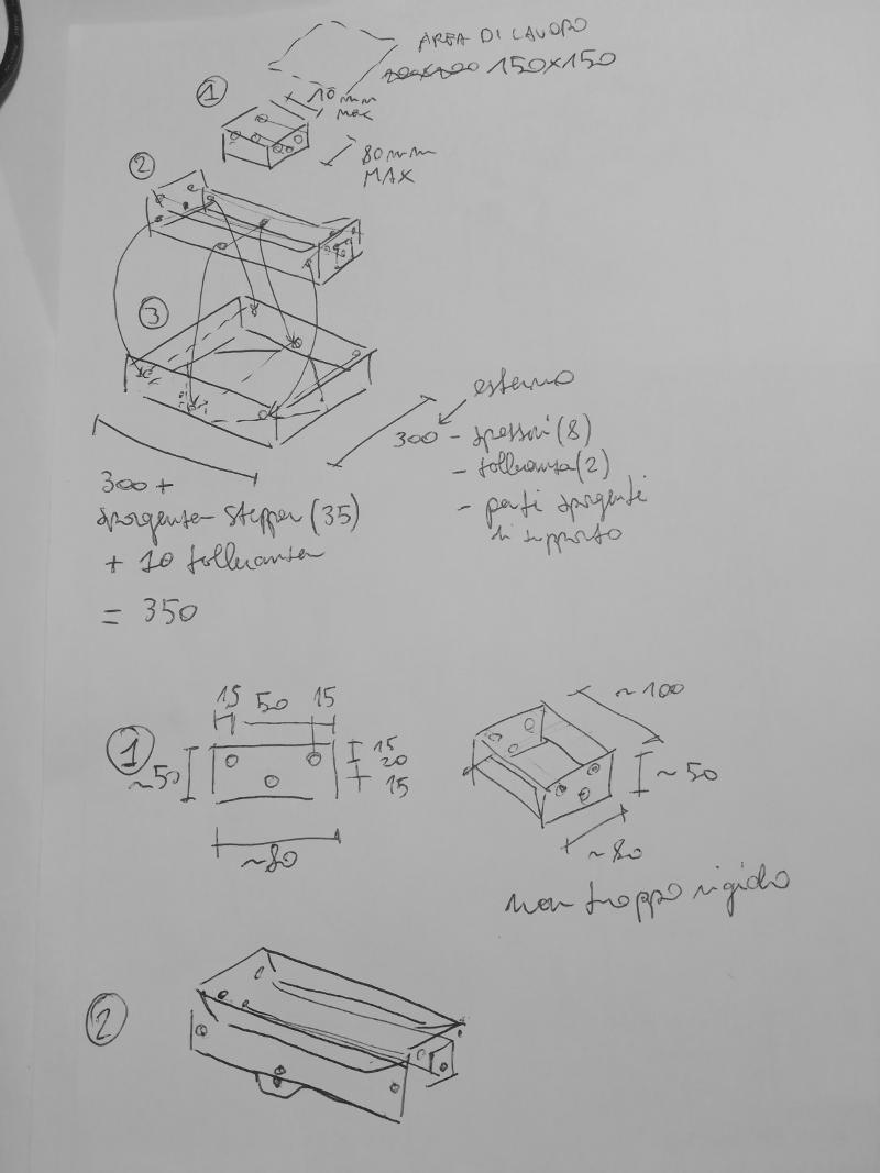
And some detail about connections and parts in 3D printing.

More tutorials of Onshape
At the beginning of this week I realized that my knoledge of 3D modelling was to weak to model a complex machine. During the past assigments I already tried several softwares and the one I liked the most had been Onshape and I decided to deepen my knowledge in this software.
I searched for video tutorials and I watched as many as I could. I found them in the Onshape official page for tutorials. I understood better some key concepts of Onshape and of 3D parametric modelling such as: part modelling starting from a sketch, parametric design with quotes and constrains to sketches, assemblies of parts, output drawings, export of faces and parts, sharing of the model, versioning, etc..

Modelling parametric with Onshape (first part)
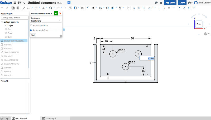
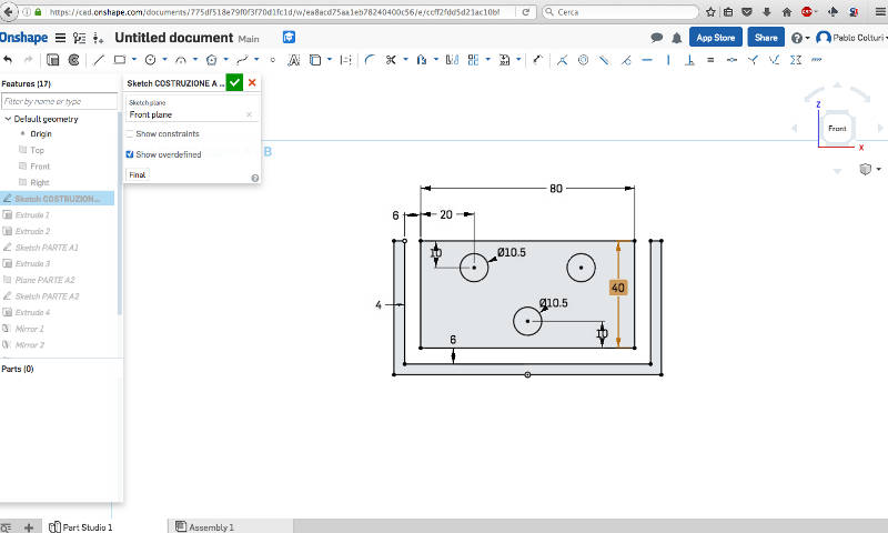
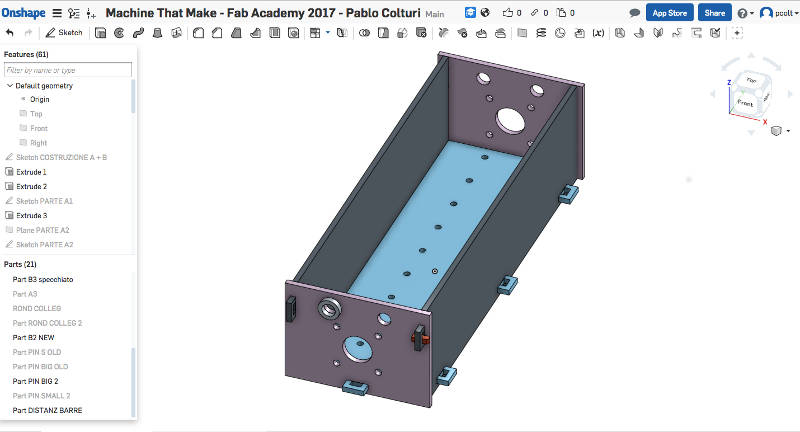
I started from the translating element which is moving along a linear axe. Everything I did was parametric so I could change overall dimensions and even small details and everything automatically was rescaled. I found that very usefull along the modelling process.
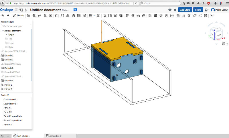
Here below one example, I scaled the height of the box from 50mm to 40mm and everything was automatically scaled.

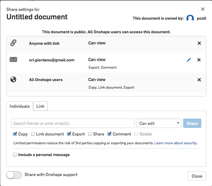
Sharing the design with the group
Finally I found very easy to share the model with my group with Onshape.
Laser cutting (first part)
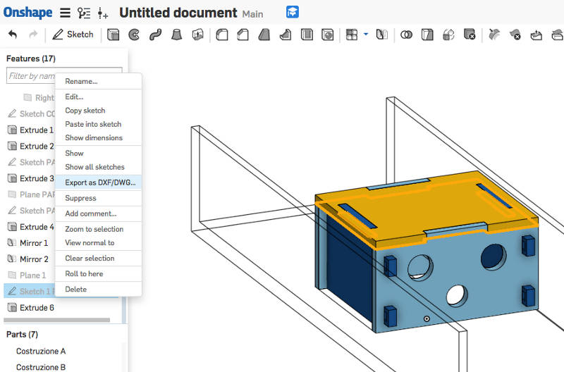
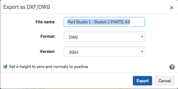
I found very easy to export the faces of my model to dwg file ready to be cutted.
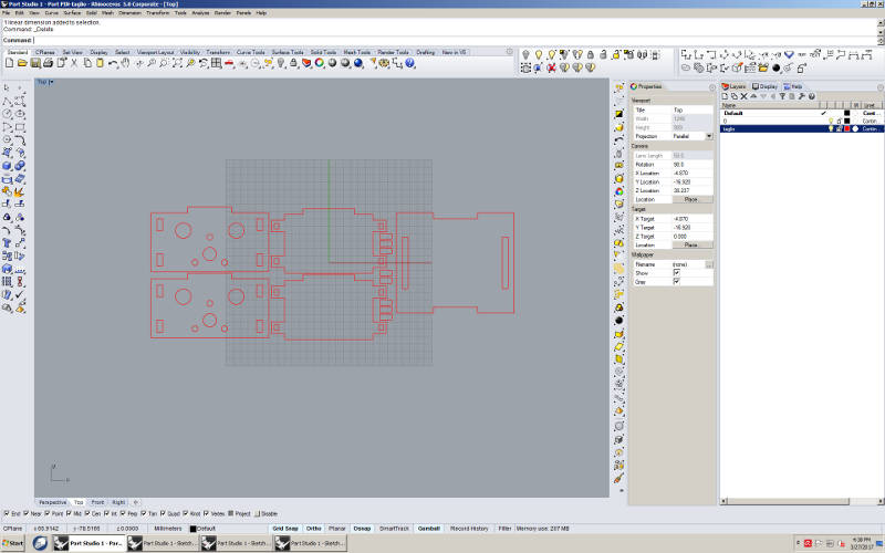
Then I imported the drawings in Rhino.
I put everything to be cutted in one unique layer in Rhino.
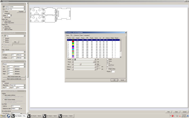
I set 3,4 of speed in the settings for 4mm sheet of playwood.
During my first cut I did a mistake: I chose a 5 mm sheet of playwood instead of 4. My pieces obviously were not matching with each other. So I did a second cutting with the right material: 4 mm playwood.
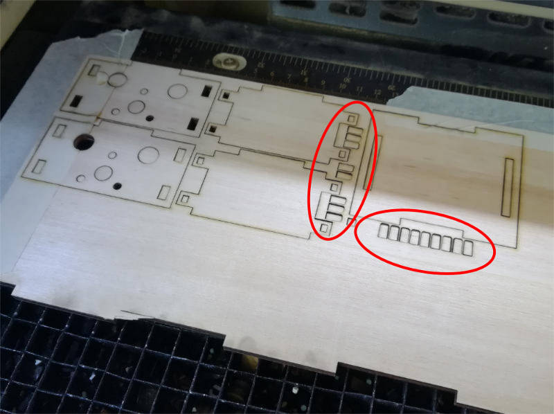
The result of the second cut was well cutted but I had some troubles with the small pins that falled inside the net of the laser cutter. I did more than it was needed but still I lost lot of them. I should put some tabs in the drawing to keep them linked to the wood sheet.
Putting together (first part)
When I did the assembly I figured out that there were some mistakes.
- Add some press-fit pins to fix the cover of the translating box.
- Move the guides far from the the center because there will be an interference with the motor.

Modelling parametric with Onshape (second part)
I completed the 3D model with the goal to do something that was modular. In this way I could use the same design to build a machine with 2 linear axes.
During the design process I did several modifications to the 3D model. Everything was easy because the model was completly parametric and almost every part and component was hierarchically depending to each other.


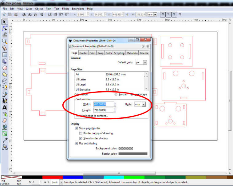
I exported the surfaces in .dxf format and I opened them in Inkscape.
In document propetries I re-sized the folio depending on the surface of the piece of playwood.
To each line the red color.
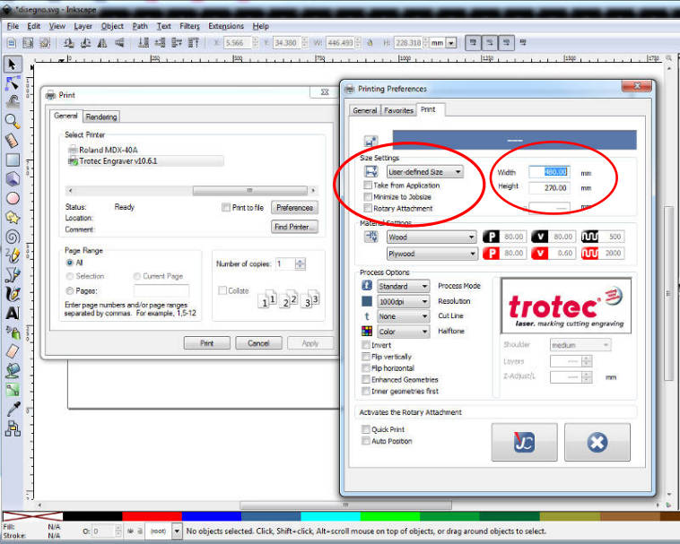
In the printing preferenes I set the dimensions of the folio so they matched the dimensions in the document propetries.
Laser cutting with Trotec machine
First I cut the 4mm playwood folio to the working area of the Trotec that is 300mm x 600mm.
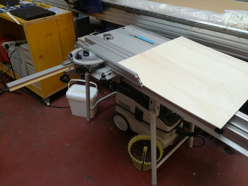
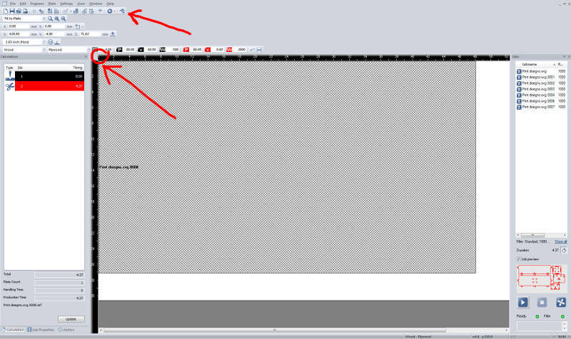
In the software of the Trotec laser machine I moved the printable area to the place where the wooden folio was placed. I did the focus and I started the filter of the machine.
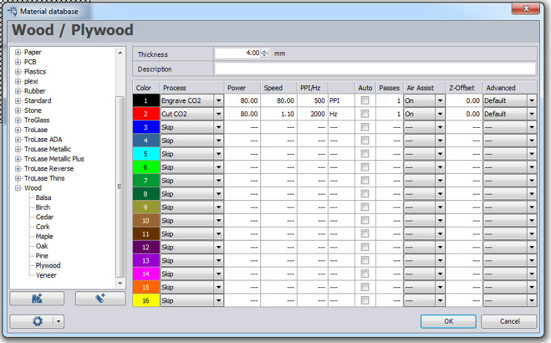
In the material database I set these parameters for 4mm playwood:
- Power: 80%
- Speed: 1.10
- PPI/Hz: 2000
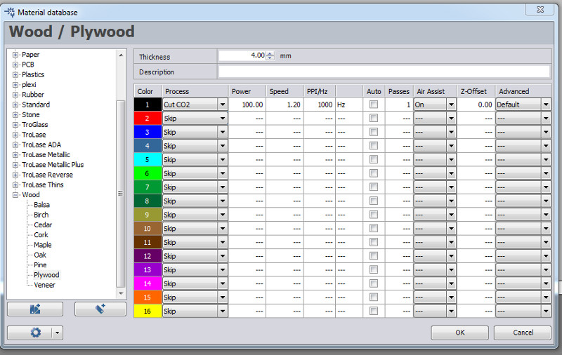
I did a second cutting following slightly different options suggested by Tiziano:
- Power: 100%
- Speed: 1.20
- PPI/Hz: 1000

Putting together (second part)
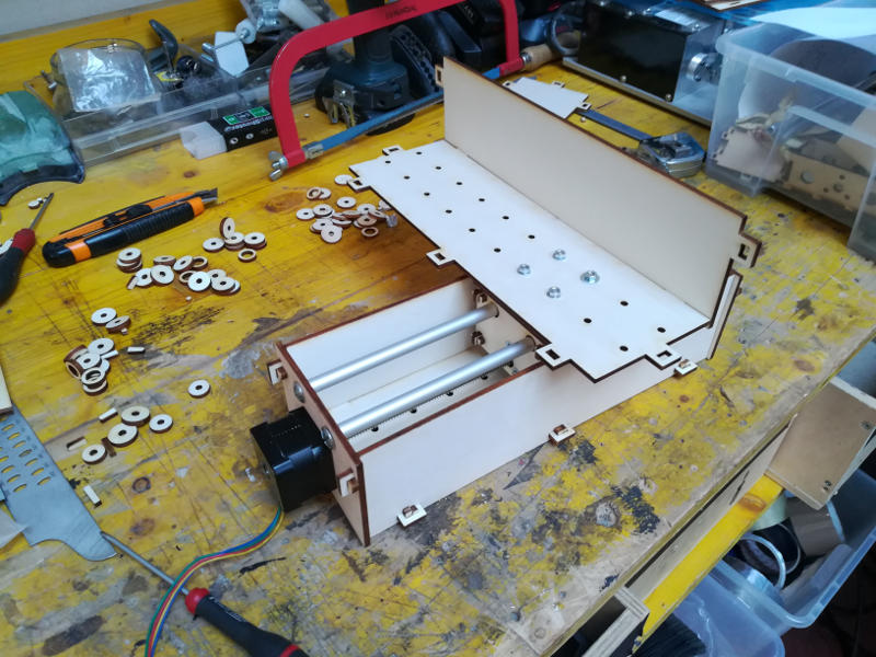
Finally it was time to do the assmbly of all the mechanical parts.
I collected all the screws, bolts, rods, etc. that I needed.
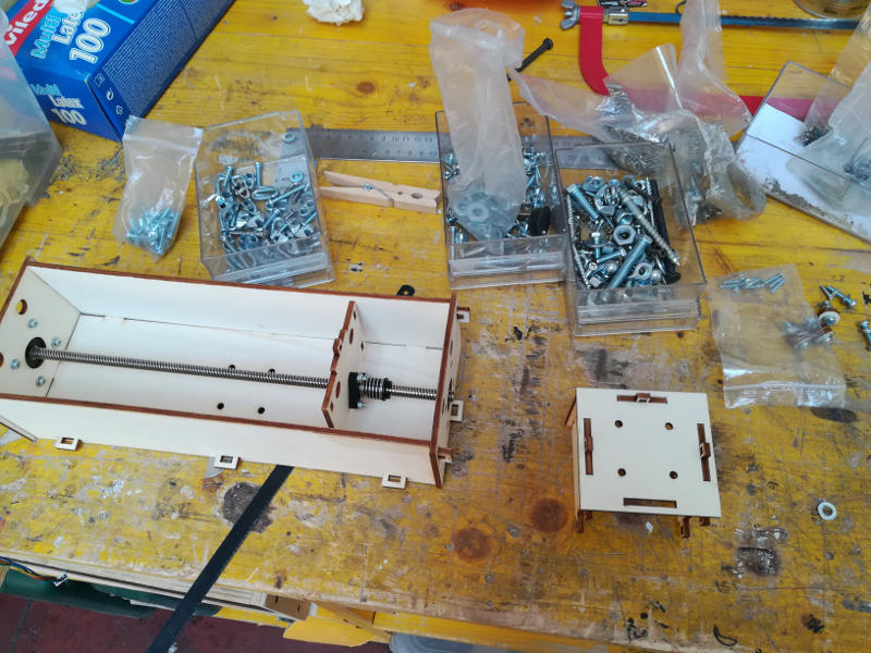
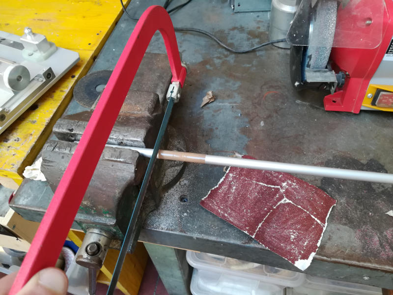
I started the assembly of the first linear mechanical axe.
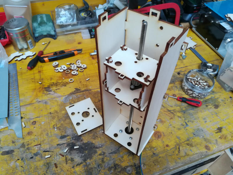
I cut the rods that will be the guides for the sliding element.