Assignment:
Embedded programming
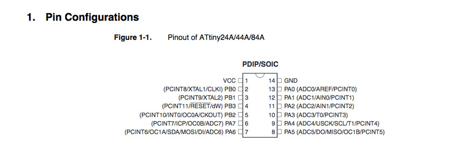
A_Read the ATtiny44 datasheet.
B_Program your board to do something.
B_Program your board to do something.
A_Read the ATtiny datasheet
Datasheet note
I started reading the ATtiny datasheet and realized after 50 pages that I would never assimilate more than the very basics about the pins, the functions and the overall arquitecture of the board. Nevertheless I scanned through the datasheet document to get a general idea of the complexity embedded in such a tiny chip. I do not pretend to understand even a bit of how it actually works other than understand the functionality of each pin types. The ATtiny is a brain capable of executing orders (programs) and dispatch it to peripheral devices.
I collected screenshots of my readings in a PDF document: Notes on ATtiny datasheet
B_Program the ATtiny44 with Arduino IDE.
Dowload and set Aduino to programm the Attiny44.
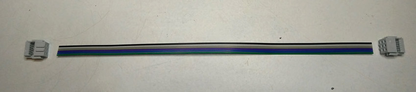
The first thing I did was to make my own serial cable.
I downloaded Arduino IDE and installed it. Because by default ATtiny is not included into Arduino Board manager the ATtiny package has to be downloaded.
Go to Arduino preferences, Find “Additional Boards Manager URLs”.
Paste this URL into the field (use a comma to separate it from any URLs you’ve already added):
Click OK to save your preferences.
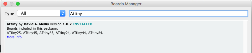
Open the boards manager in the "Tools/Board Manager" menu.
Scroll to the bottom of the list and select the ATtiny or write ATtiny in the search field.
Click the install button on the right side.
The word "INSTALLED" should appear.
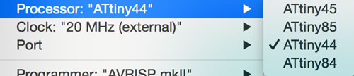
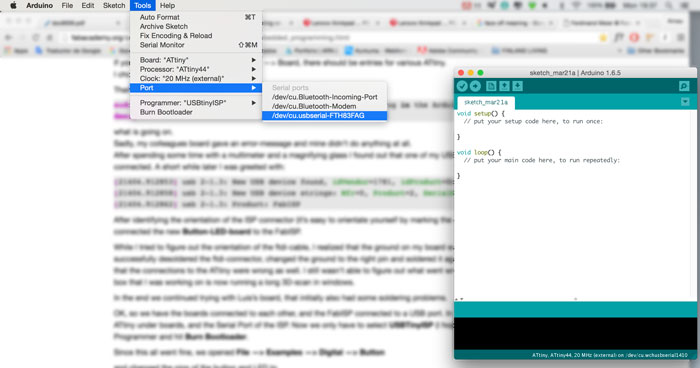
Navigate to the "Tools - Board" and select the ATtiny
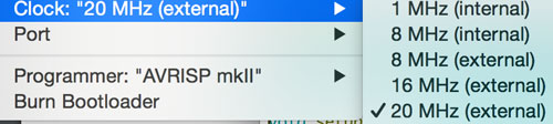
Now it's time to select the Processor (ATtiny44 ) , the clock (20MHz), the Programmer (USBtinyISP) and the correct port (the USB port the board is connected to)

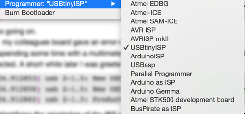
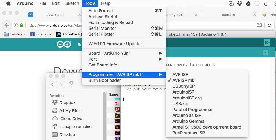
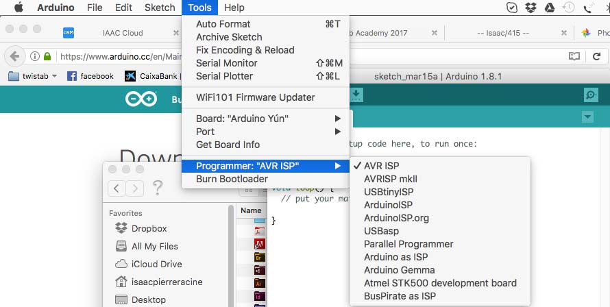
I decided to program my Attyny using both my FabISP (the one I made during the elctronic production assignment) and the AVRISP MKII programmer. It is the same process with one or the other only that the Arduino menu/Tools/programmer has to be set to the corresponding programmer.

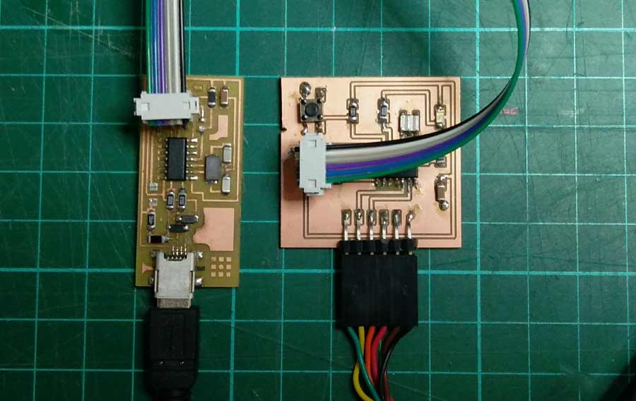
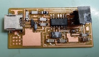
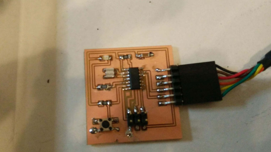
When using the FabISP it is important to make shure the solder jumper are off - that should have been done to program the FabIsp. Notice the difference between these 2 boards. The left one has the jumper and the right one do not.
Now that both the Hello Board and the FabISP (or the AvrDude programmer) are connected to the computer port, the Hello Board can be bootloaded from Arduino IDE.
Go to menu/tools/bootloader.
After bootloading a successful message should come up at the bootom of the Arduino window.
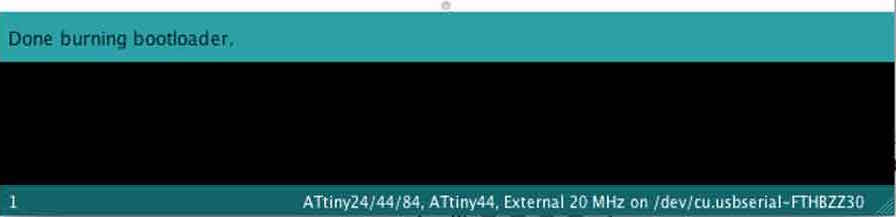
If a message error appears it is most probably due to a hardware problem and connections need to be reviewign and components tested.
If it is succesful the Hello board is now ready to be programmed either from Arduino IDE, terminal, or which ever other interface.
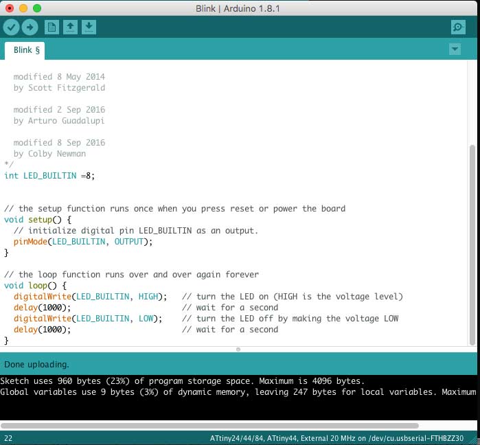
I uploaded the "blink" example script In Arduino IDE.
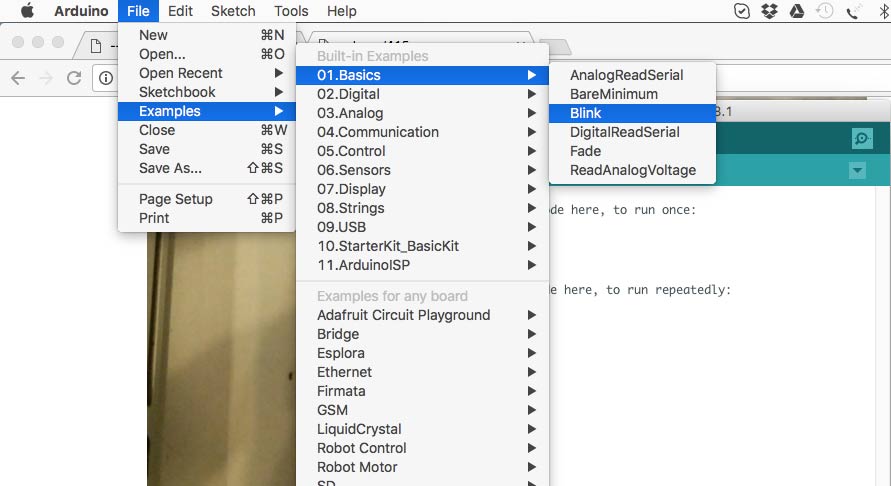
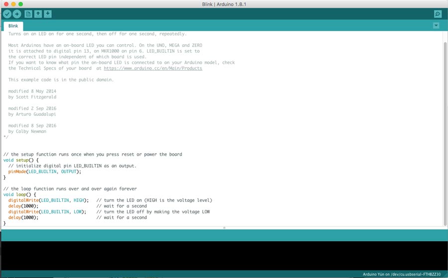
I edited the Arduino script so it fits the pin set up of my board design.
The led on my ATtiny is on pin 5 so I refered to a chart that tells to which Arduino pin it corresponds to. Arduino IDE aTtiny44 pin chart. Here 2 helpful results.
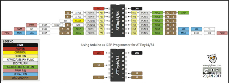
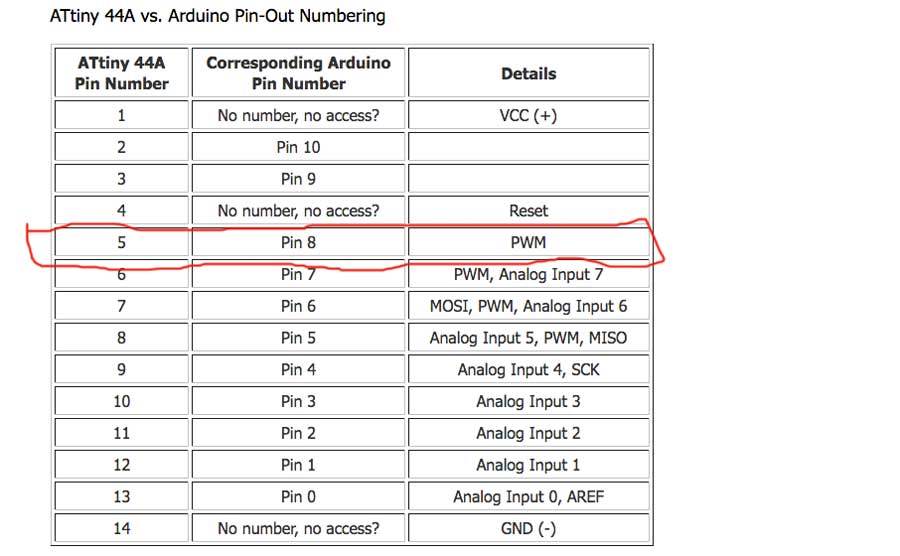
Arduino pin 5=ATtiny pin 8 so I translated this info into the code, than compiled and ran the script.
I receive no error message but the led do not light or blink as it should have.
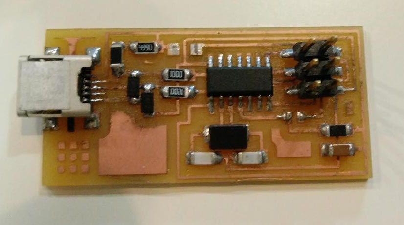
I analysed the board and realized one of the resistor was wrong. I mistaked the 499K resitor for a 1000K when selecting my components. With this resistance the current did not reach the led (too much resistance). I figured it out by-passing the resistor with another led - since the led lit that meant the board was allright and the issue was somewhere related to the led. Either the led it-self or before the led which is the resistor.
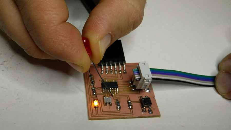
I replaced the resitor to a 100k (because there were no more 499k in the inventory) and it worked. Even though the original suggested resistor is 499k the 100k works because it is within the current margin the led can take.
Playing around to get familiar with Arduino I changed the time of the blink, loaded a botton script to make shure I understood. The following videos shows different Arduino sketches running.
Long blink
Botton
To load a script on the ATtiny it needs to be connected to the Programmer ( and also to a power source - in this case the computer through FTDI cable) but once the program is loaded the ATtiny can execute just using the power source. Though to communicate with the computer using the USB port it requires especifically a FTDI cable because it contains an integrated chip that allows communication. A normal USB cable will provide power but not communication. Here is a video of the ATtiny running an Arduino fade sketch
Fade sketch
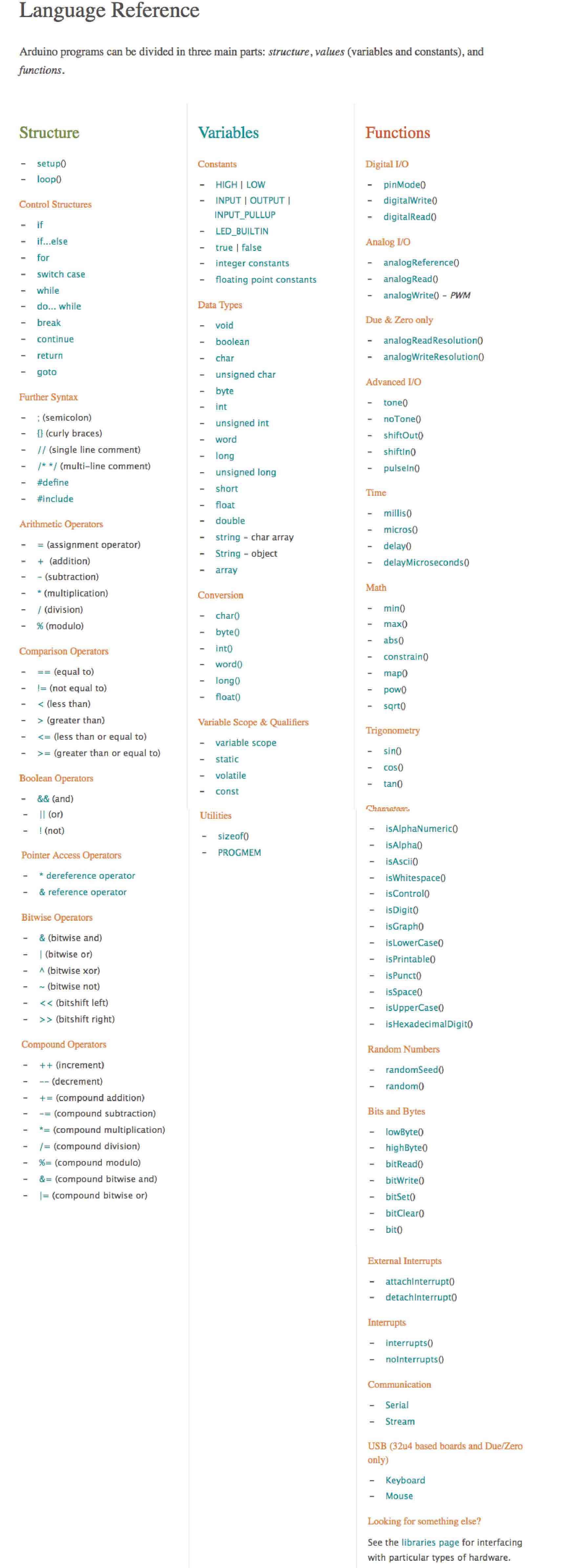
I read the Arduino tutorials from bottom to end to get familiar with the programming environment. It is the first time that I challenge my-self to writing code so I need to get familiar with many concepts before feeling comfortable with it. I also studied the Arduino reference pagethat I found helpful to refer to when I have doubt with the language, syntax, etc.
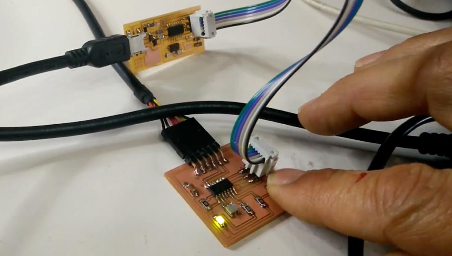
Than I wired my board with a light sensor, one green and one red LED. I wrote a sketch so when there is light the Green LED blinks and when not the RED blinks.
I used a breadbord and an ArduinoUNO and my connections went like that:
LED red =pin 13
LED green =pin 12
º light sensor = A0 + resistor 16 0 (Brown/Blue/Red) = 1600ohms
light sensor power from 5V pin
A resistor 77 ohms (Violet, violet = 77) between pin 12 and the Cathode of the Green LED
A resitor 77ohms between pin 13 and the cathode of the Red LED.
NOTE: The resitor made the Red led very dimmed and I do not know why?
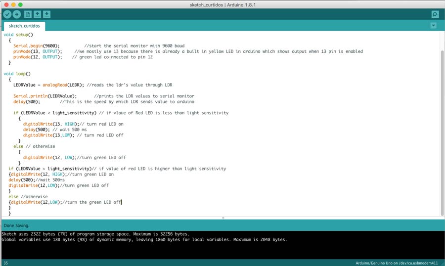
Here the link to the executed sketch on an ArduinoUno
I created a Language reference document for Arduino IDE. I will be using it constantly as I start writing and editing sketches.
I intended to program my Hello Board using C following one of the tutorial recommended by our instructors but I could not go further than "error message" trying to log onto the FabISP and HelloBoard in terminal.
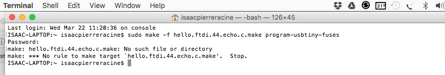
That was enough to make me realize that I don't understand the workflow when it comes to work with hex file, make file and xcode. I did not have time to experiment further with it and program my board in C before pushing my assignment because I got side-tracked helping a fellow student with flashing his Hello Board on Arduino IDE (which I had done successfully last week using my FabISP). Strangely enough after plugging and unplugging few time to show the bootloading process my FABIsp stopped mounting. I reviewed the connections and soldering but could not fix it. I suspects that in the process, I inversed the ground connection on the 6pin or the FTDI cable and it could have blown a component. Need to troubleshoot my board now.
This week I learn how far I am from an intrinsec understanding of how coding works. I understand a little better what embedding programming means: embed a program into a chip so it can execute a code that operates peripherals electronic devices.