7 - Computer-Controlled Machining
Assignment:
Make something BIG!!!
Designing for milling. Experimenting with the workflow from design to a CNC fabricated object.
The design process
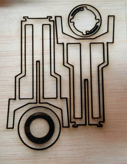
For this exercise I created a new Twistab model from a file I worked on last year. I actually had laser cutted miniatures.
Apart from an opportunity to practice designing on Rhino, this exercise is about getting the file ready for fabrication. The different step of the process are: preparing the file, nesting the pieces, make the toolpath, generate the Gcode and mill.
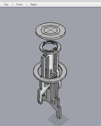
When scaling the miniature model to real life size I added quite a few details which could not be implemented in the miniature scale. For example pocketing on the reverse side of the footrest, the external diameter and review the shapes of the inside hole of the legs, and adjust the tolerance.
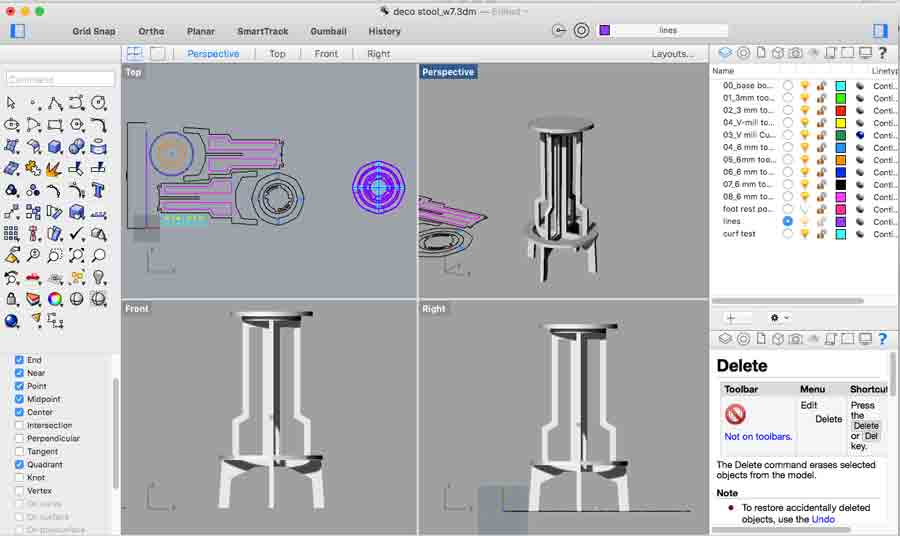
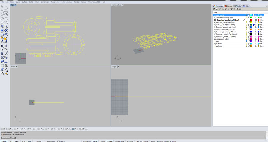
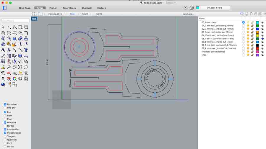
When preparing the file it is important to make shure there are no repeated curves and that they are all joined. A gap in a curve will clug the workflow. Make shure all curves are joined. Next select all curves and enter tne "make2d" command - eliminate hidden elements in all planes. This command sends all the elements on a new layer called: make2D so the old layers can be deleted.
Another helpful command to make shure all the curves are on the same plane and not repeated is "planar srf".
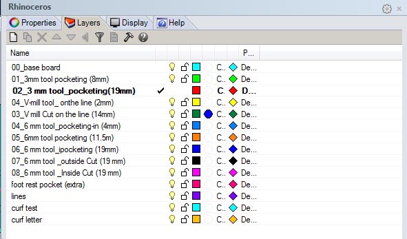
Next I created a strategy for milling, reassociating each layers to groups of objects. Each object has a color and a function. (I still have a lot to learn as per the best method using color and to organize this part of the workflow)
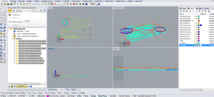
Making the toolpath
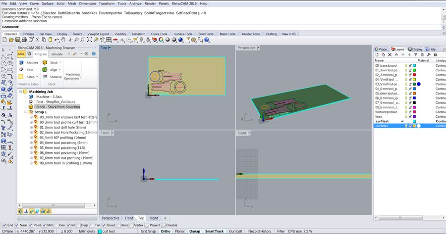
I used rhino cam on window to create the toolpath. I am looking for an open source solution but yet has not found it. I have used the shopbopt interface directly in the past but not Rhinocam yet.
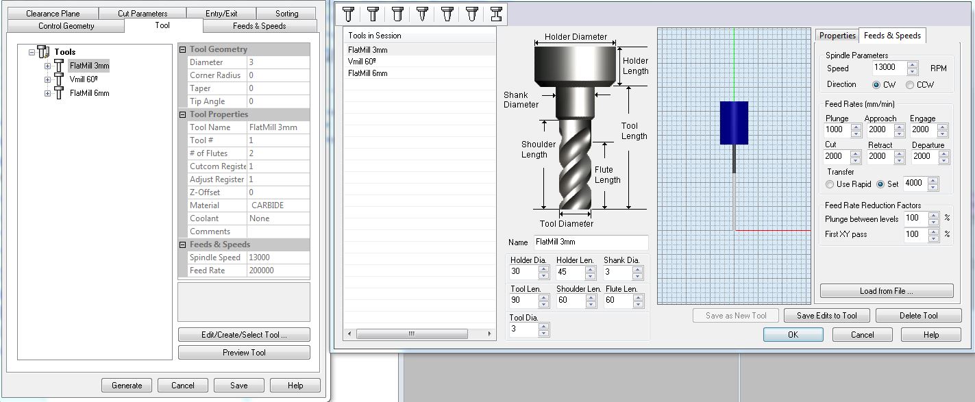
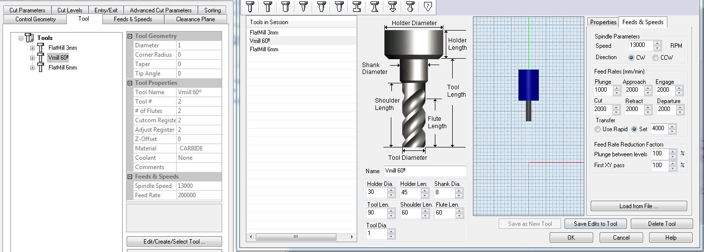
I am using 3 tools for this job (3mm. and 6mm. flat endmill and a Vmill bit). I could do without the 3mm. but I will prepare it anyways.
I started by creating the stock - 1250 x 2500 at -18 mm. The -18mm is so the 0 of the Z axis is on the top surface of the board.
After I set the 3 tools that I will need: a 3mm flat end mill (for the screws that hold the board and the corner holes), a Vmil 60º to chamfer the top disk of the seat, and a 6mm flat endmill for the rest of the job (pocketing and profiling).
I set the the "feed and speed" parameters for each tool as specified for the specific shopbot I'll be using.
Since all the infos about tools, milling depth, inside/outside/on the line and the type of machining (pocketing, profiling etc.) come from the Rhino layers all I need to do is translate these infos into each toolpaths.
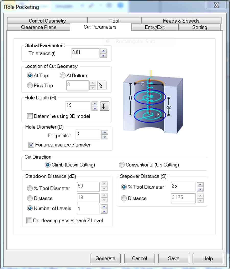
I am using "drill hole" function to drill the holes where I want to put screws that will hold the board to the machine bed. I used also "drill hole" but at 19mm deep for the whole in certain corners of my design. I set it up to drill the total depth of the whole at once.
I use pocketing to empty (retrieve)material in some areas between 2 curves (below part of the seat) or within the circle which diameter is bigger than the size of the endmill.
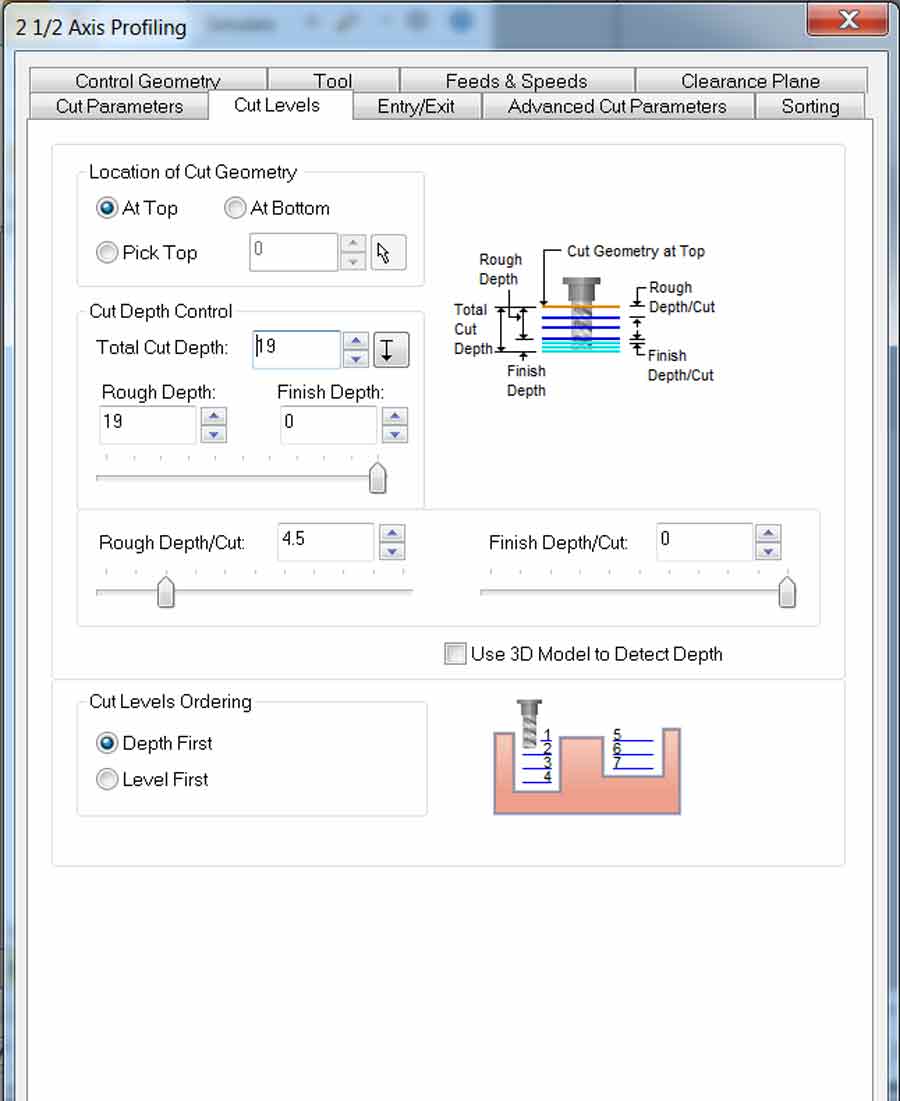
I use profiling for the part to be machined with the 6mm endmill. The curves located on the external contour are to be milled outside the line and the ones that are located inside the shape of the stool will mill inside the line.
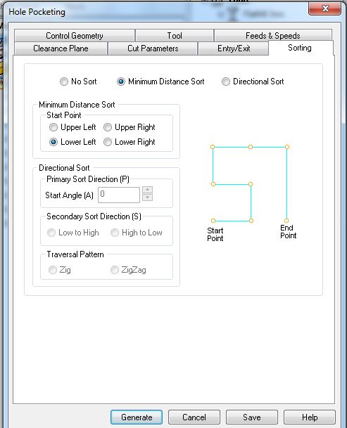
In each toolpath I set the sorting tab to "minimum sorting distance" so the machine follow the shortest path throughout the job. That helps speedup the job, save time and be more efficient.
I also integrated a .5mm tolerance kerf test for 18mm plywood and created the tool path for it. The kerf test is milled first and before making the toolpath so the join and slotting part of the design can be adjusted according to the kerf test result. In this case I adjusted the file simply by scaling the whole design to 18.1 mm. for the slotting part. In the case of having the design parametric just adjust the corresponding parameters.
I am using material that I have used in the past and know from experience this type of plywood (18mm okume plywood) has to be milled at 18.1 to get the perfect slotting.
The total milling depth is 19mm and it will mill 5mm depth at each pass. That means 4 pass in total. I used these parameters for every toolpaths.
The following images shows the complete tool path and a simulation of the actual job.
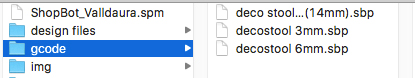
Generating the Gcode
Once each tool path has been created the Gcode has to be generated. I selected all the toolpaths associated to a specific tool and post it to generate the Gcode. I repeated it for each different tool, ending up with 3 gcode files.
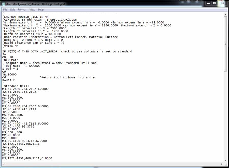
The Gcode can be read and analysed to verify the job is correctly programmed. It consists of a series of information related to the miling parameters the machine will execute and sequences of XY and Z axis coordinate. It is possible to edit the Gcode directly from the text file.
Milling
Before anything the board needs to be placed on the machine bed and placed properly in the corner where the XY 0 of the machine is set.
Next we need to set the XY 0 for the job and the Z axis 0 - note that it is important never to change the X and Y zeros within a job. But with every new tool change within a job the Z axis 0 had to be reset.
Than I opened the Gcode 1 to drill the 8mm holes to screw the board to the machine bed and drilled the holes.
When screwing the board to the machine it is important to make shure to screw themm tight enough for the board to lay completely flat on the sacrificial layer (the layer of plywoood placed on the Shopbot).
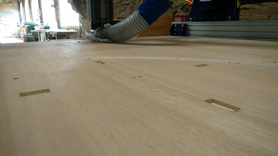
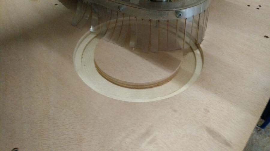
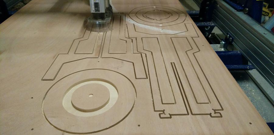
Than I sent the 3 mm. drilling holes (for the corner where I needed a 90º angle joint) and the pocketing of the footrest.
And the the 6mm. pocketing and profiling.
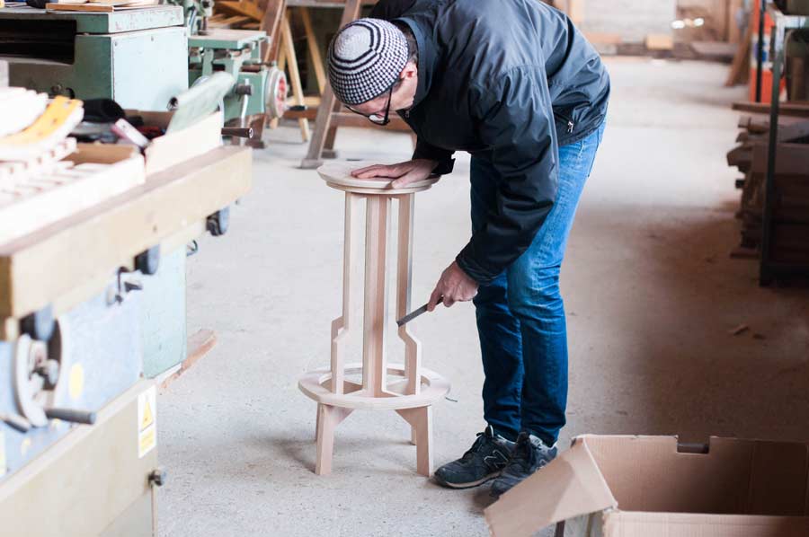
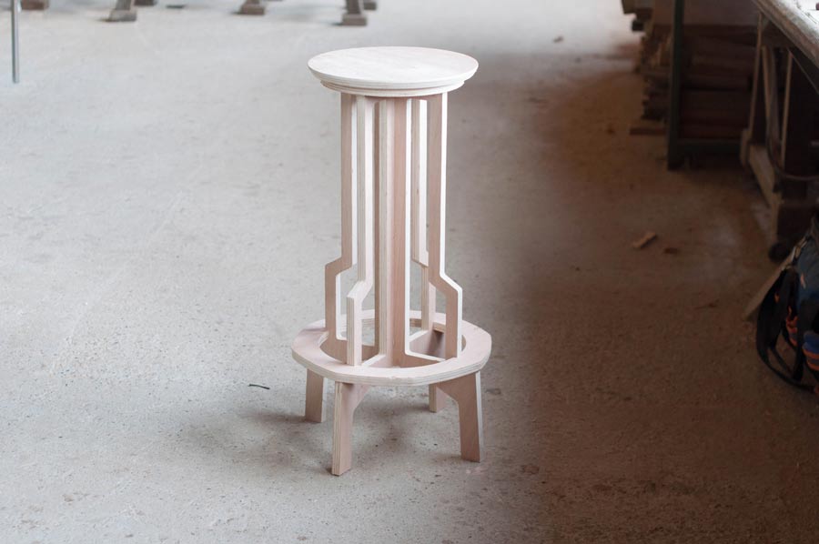
The job came out pretty well for a first prototype, enough to get conclusion in terms of the proportion of the design and have the possibility to physically see the details and flaws.
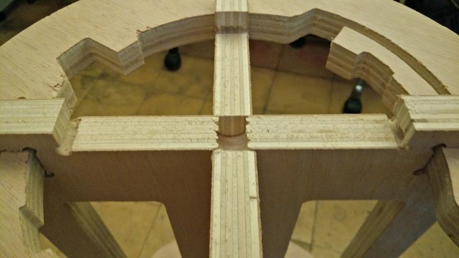
The most important details that failed was the pocketing of the footrest. I made a 4mm. deep pocketing the size of the material (18.1mm) but it came out narrower so I had to chisel material out to make it fit. The reason is that I had set the toolpath "inside the line" while it had been designed to be on the line.
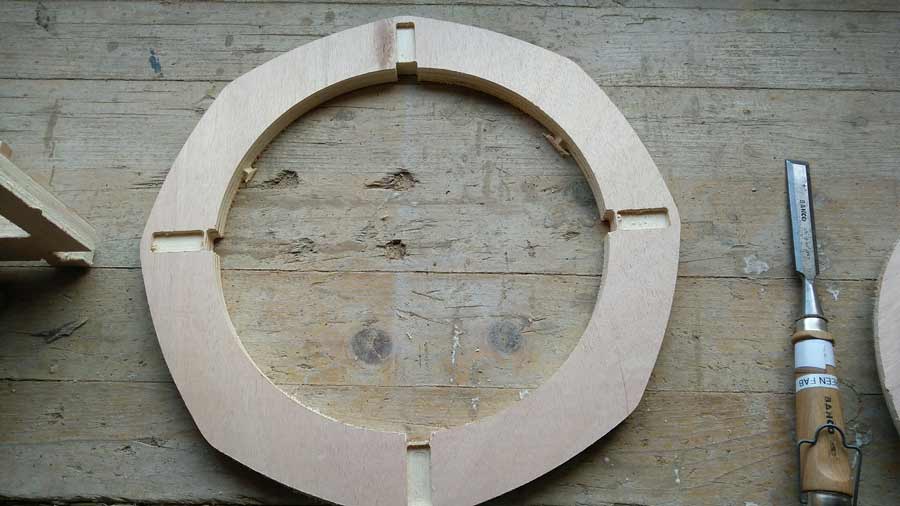
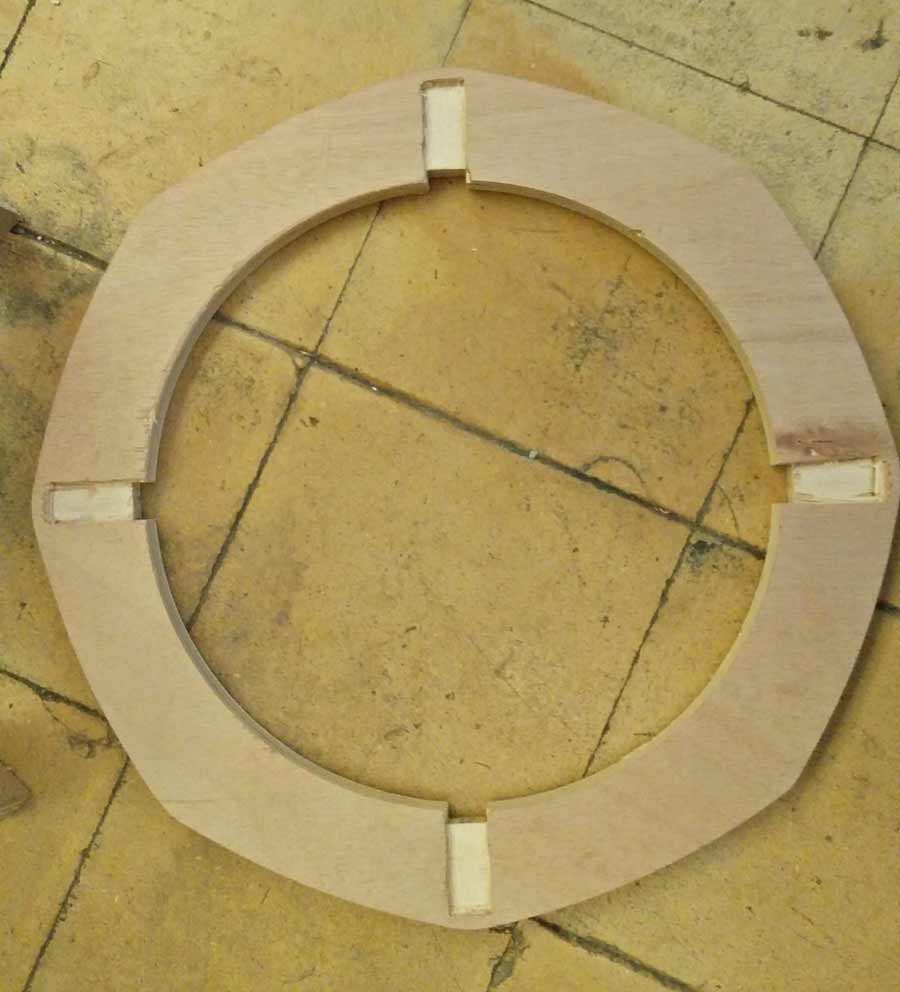
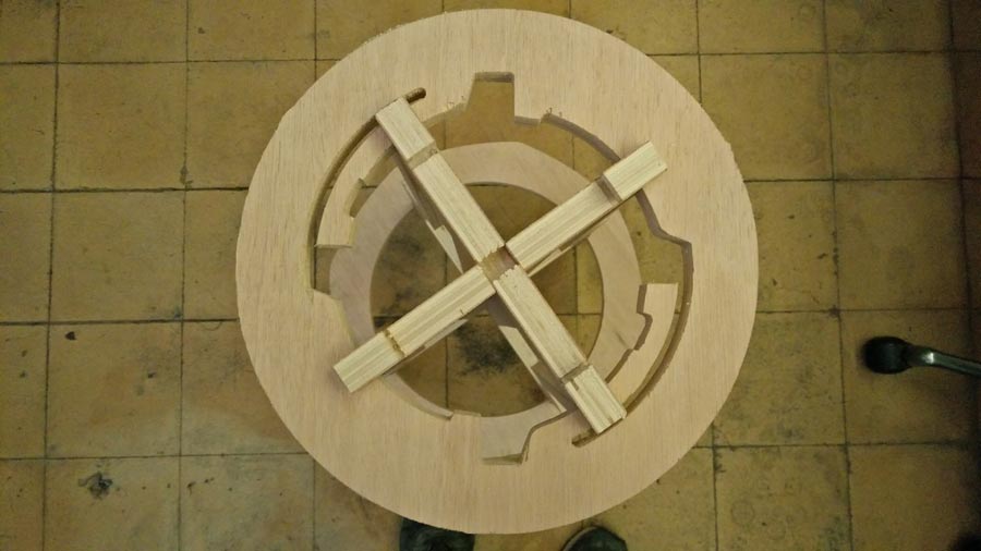
For the rest of the pieces, a little filing did the job and it slotted, assembled and fitted easily.
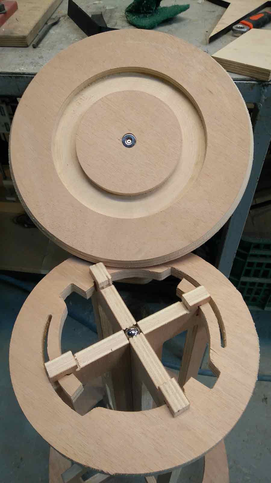
This Twistabis a swivel magnet version - the seat is joined to the legs using a magnet system - A 18mm steel ball is inserted into a whole pocketed in one of the leg and a washer magnet is attached (screwed) inside the pocket in the bottom part of the seat. So the top disk (seat) is attached and can also swivel.
To get a final version of this model I will adjust design and technical details.
What I learn is to take time to do things properly. Also that most of the work is about the preparation. Milling is what the machine does and the preparation what it needs to know so it does a good job. No point to go milling before 100% ready. It will only waist time, energy and material and create frustration. Making test is clue to get it right.
Download the files HERE