

Final Project

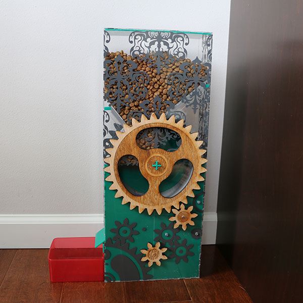
Have you ever had the problem that you go on vacation and there is no one to check on the cats?! How on earth are they going to get more food, but not eat the entire bag? My goal this semester is to fix that problem by making a cat feeder that will be timed to refill their dish twice a day.
Project Progression
Plans of the Kitty Matic: Very begining stages

Drawings from Illustrator of concept.
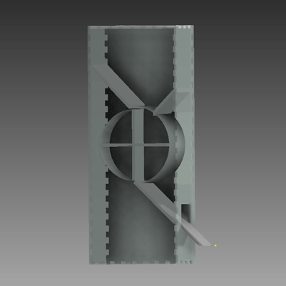
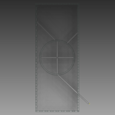
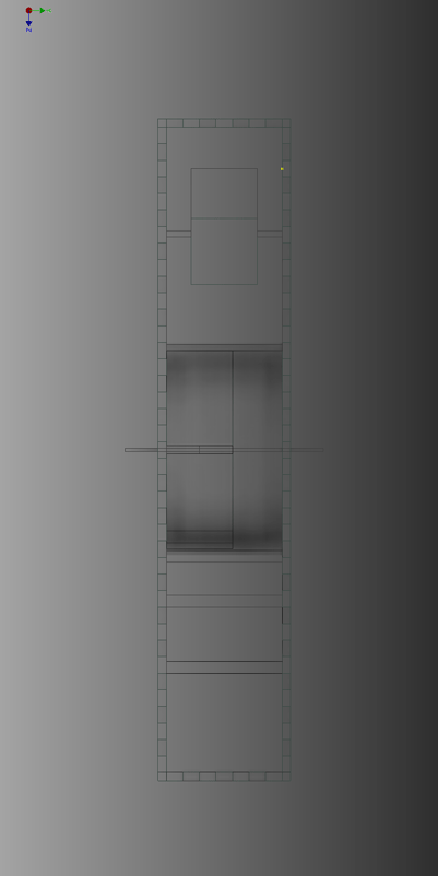
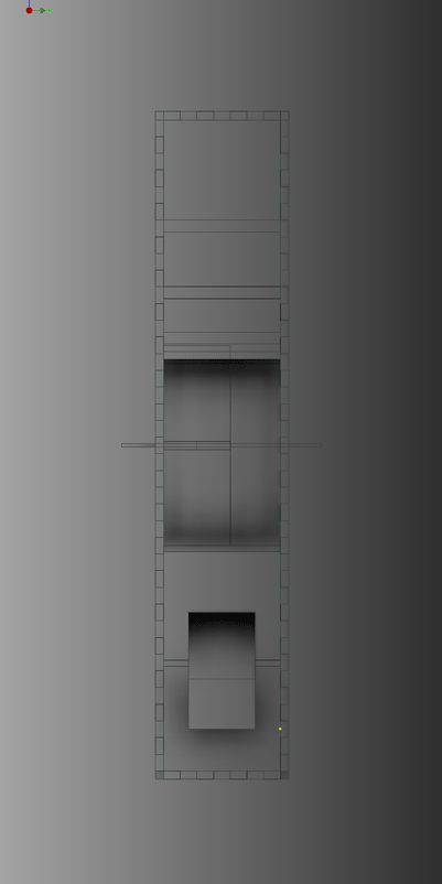
Drawings done in Inventor for the model of the project. Doing this step really helped me start to think about the design flaws and what would need to be changed as I went with the design. Possible situations with my cats, the food getting stuck or even the way the wheel turned/was held were things that were on my mind.
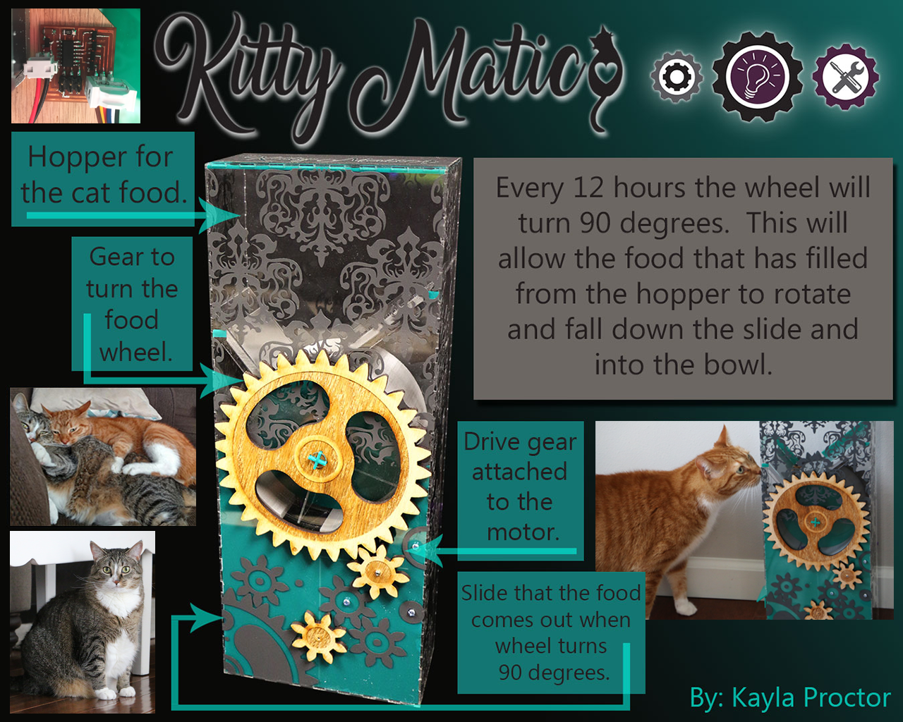
Before jumping to the next step I designed a logo for my machine.
![]()
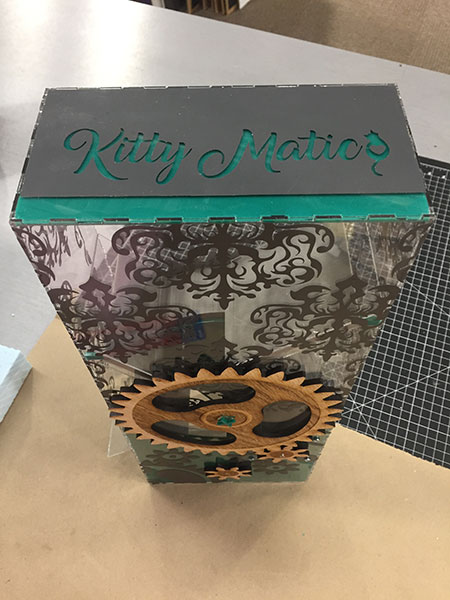
Then I made a vinyl decal for the top of the cat feeder!

The Progression of the Wheel:
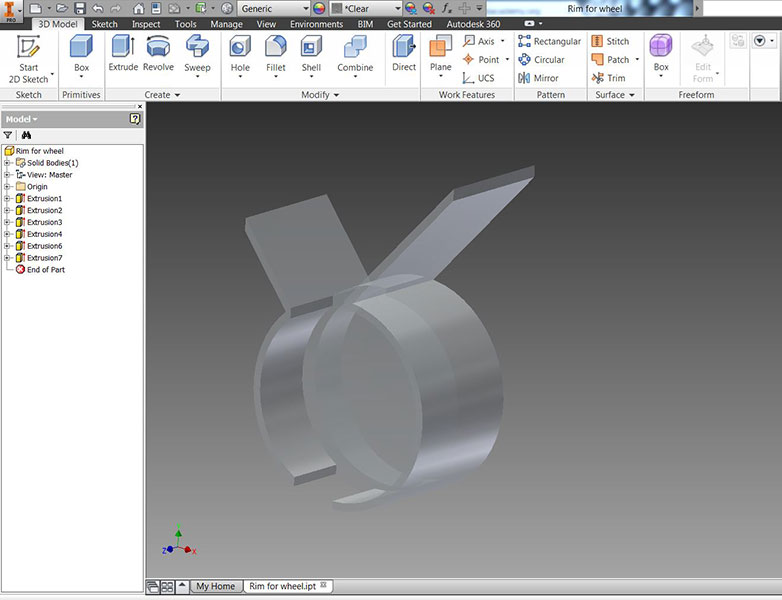
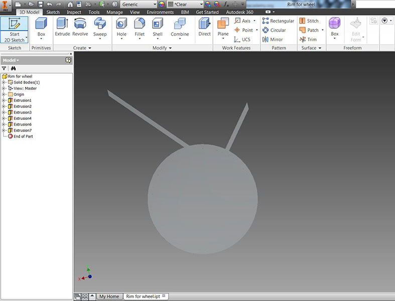
I modeled the wheel in Inventor using multiple extrusions.
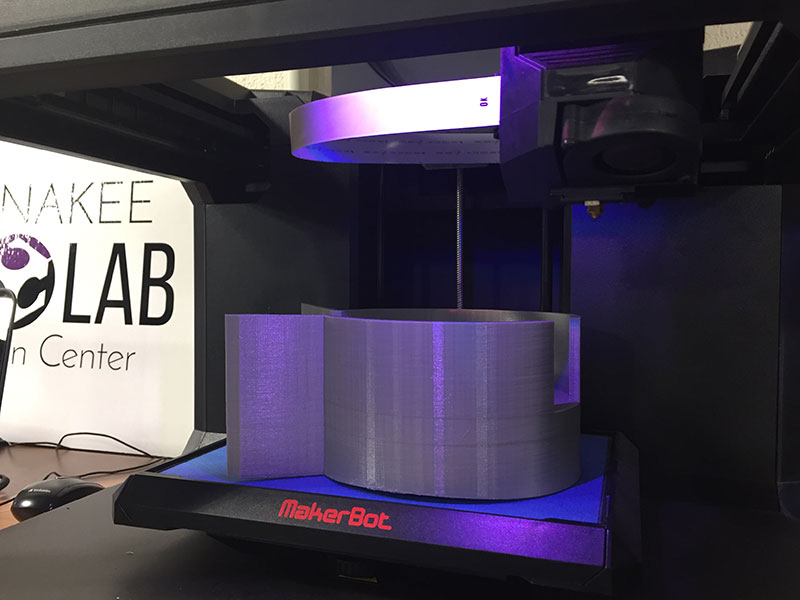
Then I set the wheel up to print in the Makerbot software using the following settings.
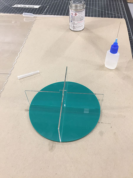
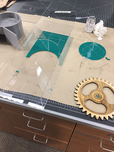
To put together anything that was acrylic (so basically my whole project) I used the acrylic adhesive.
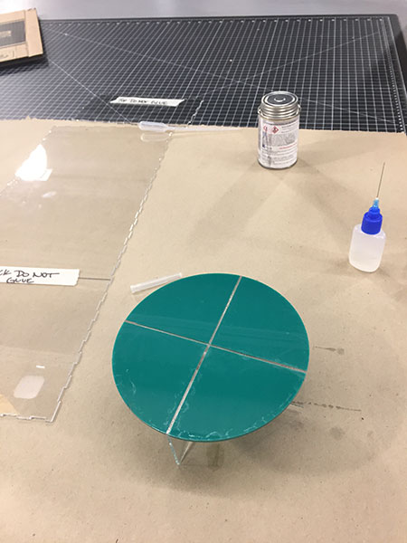
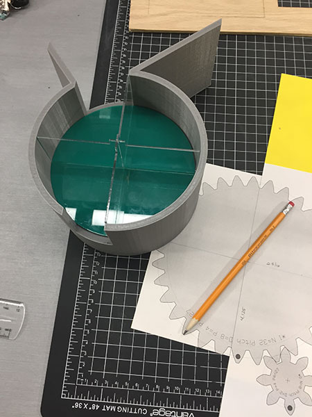
The wheel fit perfectly and spun wonderfully inside the holder. I also used an equation and measuring system to find out how far to place my gears so the teeth would move smoothly with eachother.
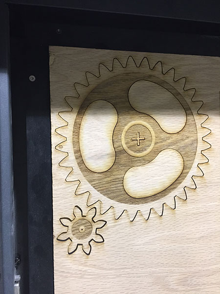
Making of the Gears:
I used geargenerator.com to help with the math for the gears and the ratio.
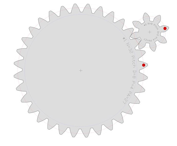
Then modified them in Illustrator.
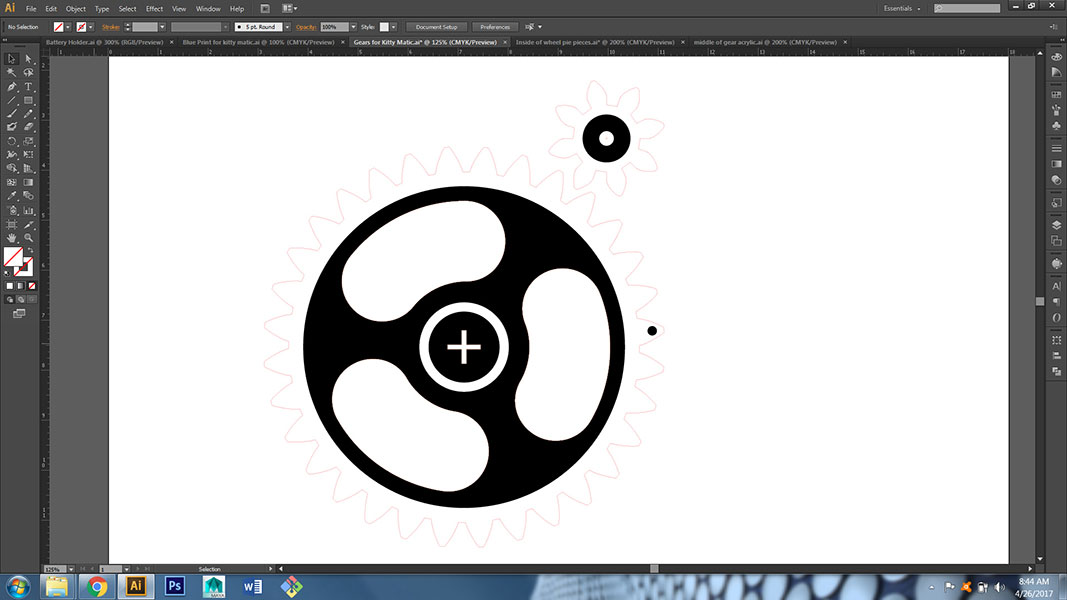
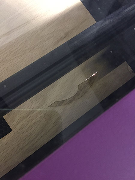
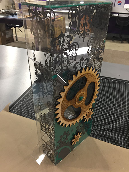
I used the laser to cut them out of 1/4" hard wood. I also added some engraving to help with design.
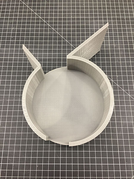
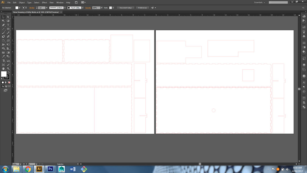
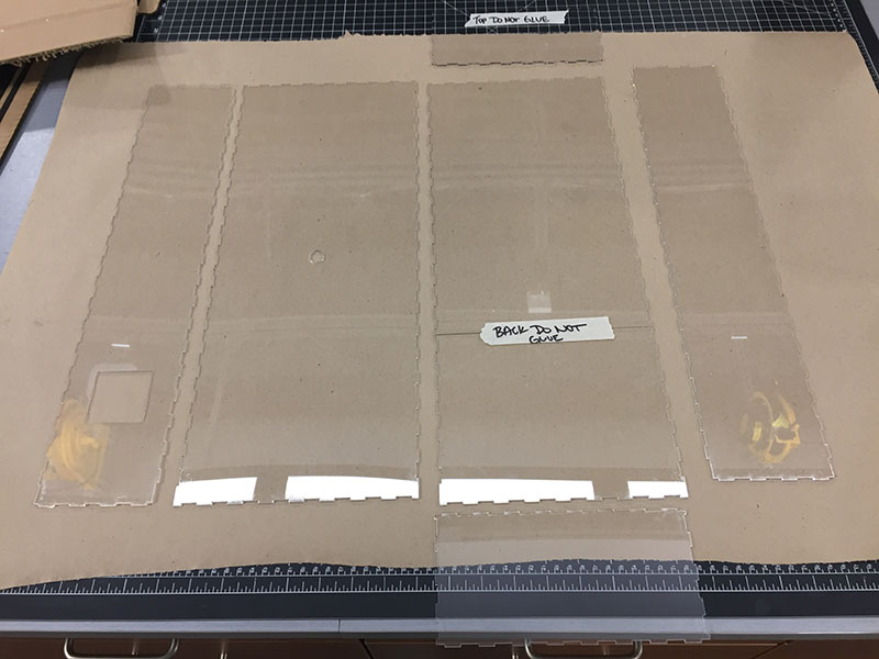
Laying out the Structure of the Kitty Matic:
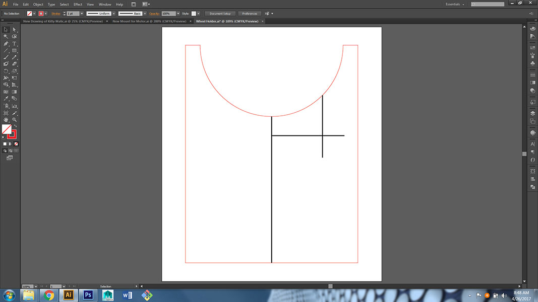
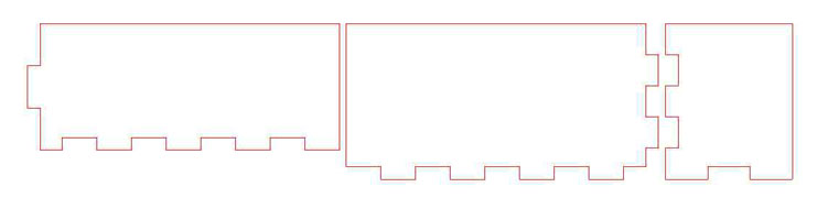
First I used the blueprints from Inventor and imported them in Illustrator. I made a few changes before I cut them out on the laser.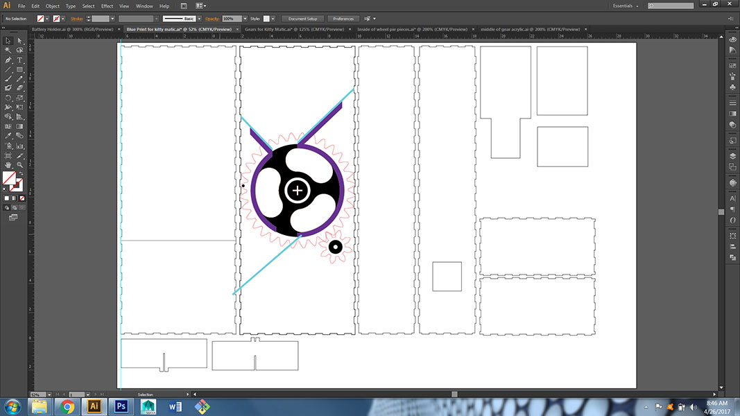
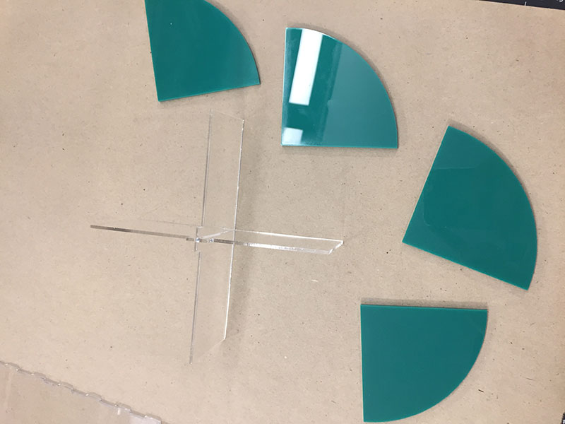
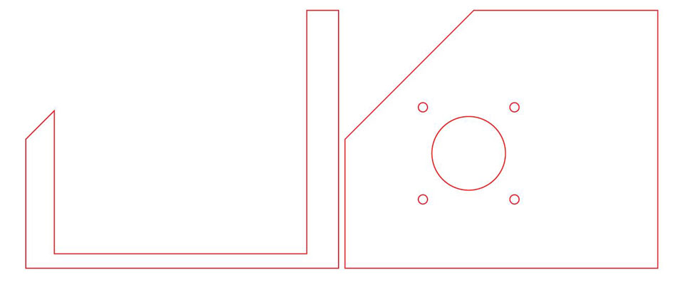
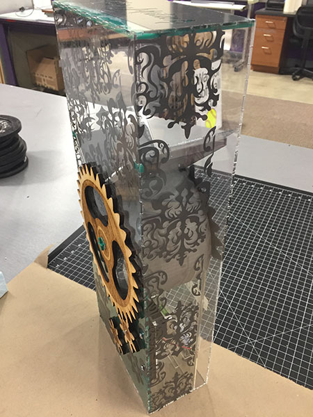
The teal piece shown in Illustrator below was designed to help hold the wheel holder in place so it would not fall down in the machine. It will lock the wheel holder along with other pieces. I have also added the slopes for where the cat food moves from the hopper into the wheel and then again down the shoot out to the cat bowl.
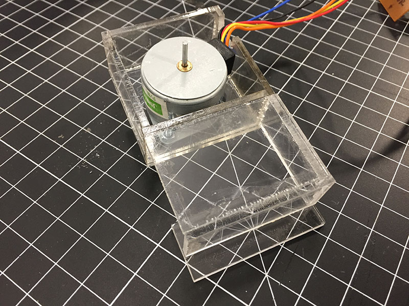
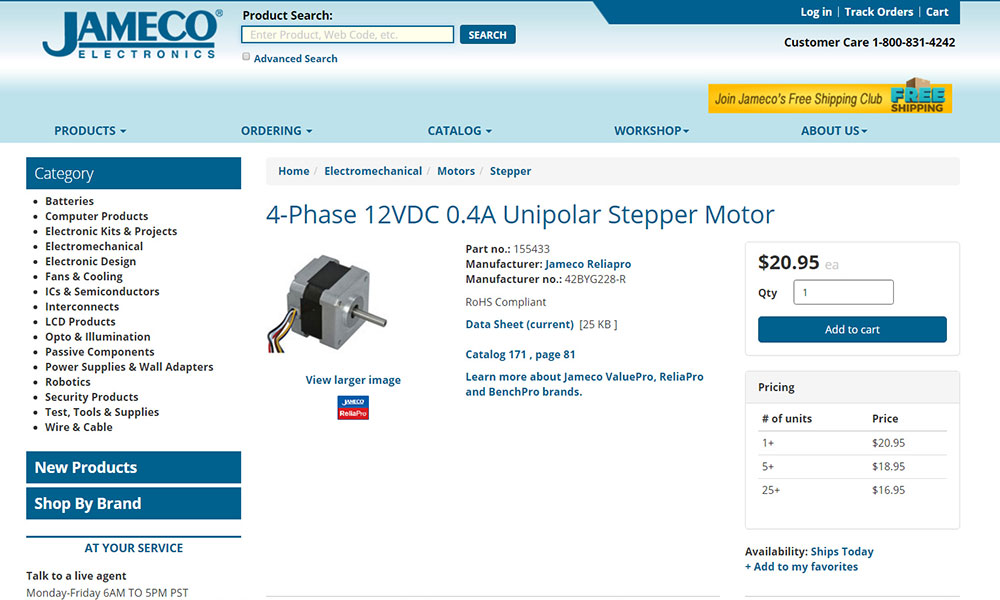
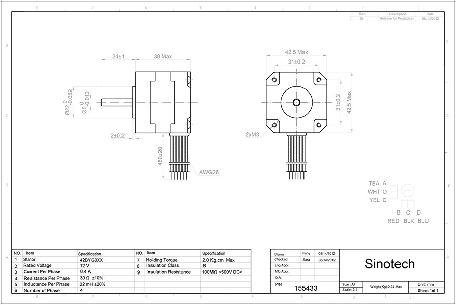
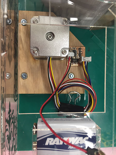
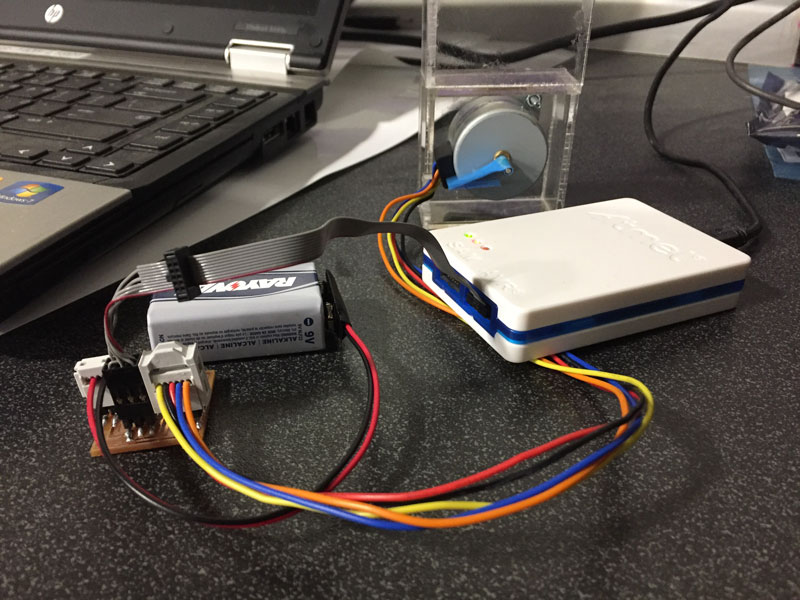
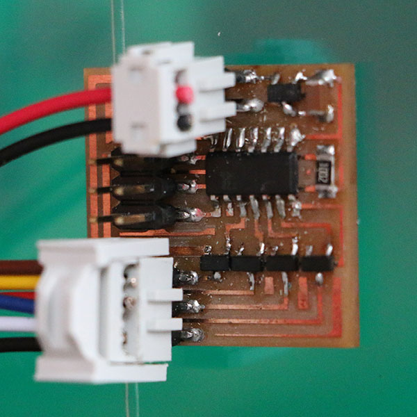
In the image below you can see the first "smaller" motor that I programmed and tried with the Kitty Matic. The data sheet and info on the motor follow. I also used this motor and the board that I made for it in Week 10 - Output Devices.
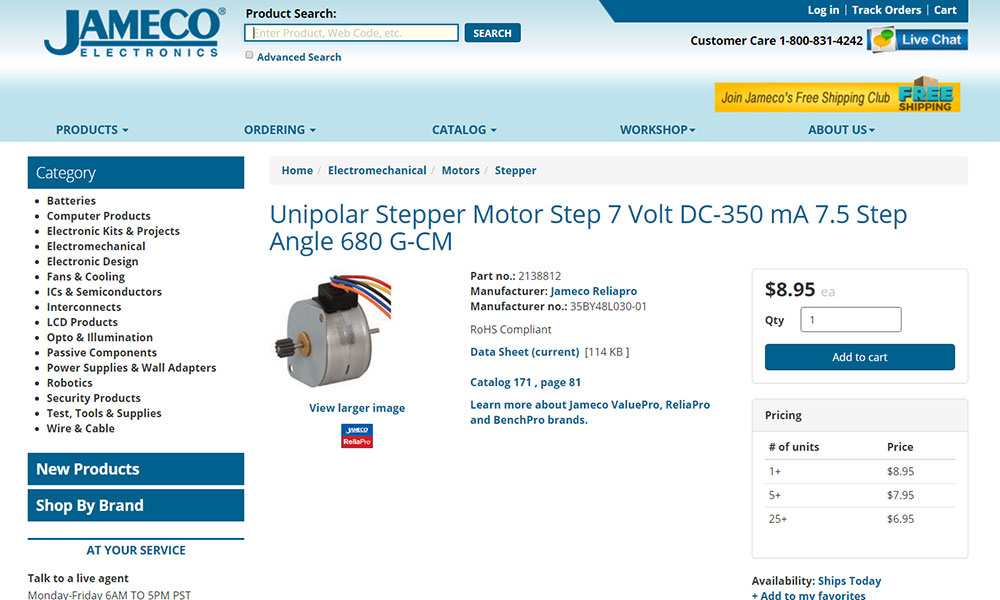
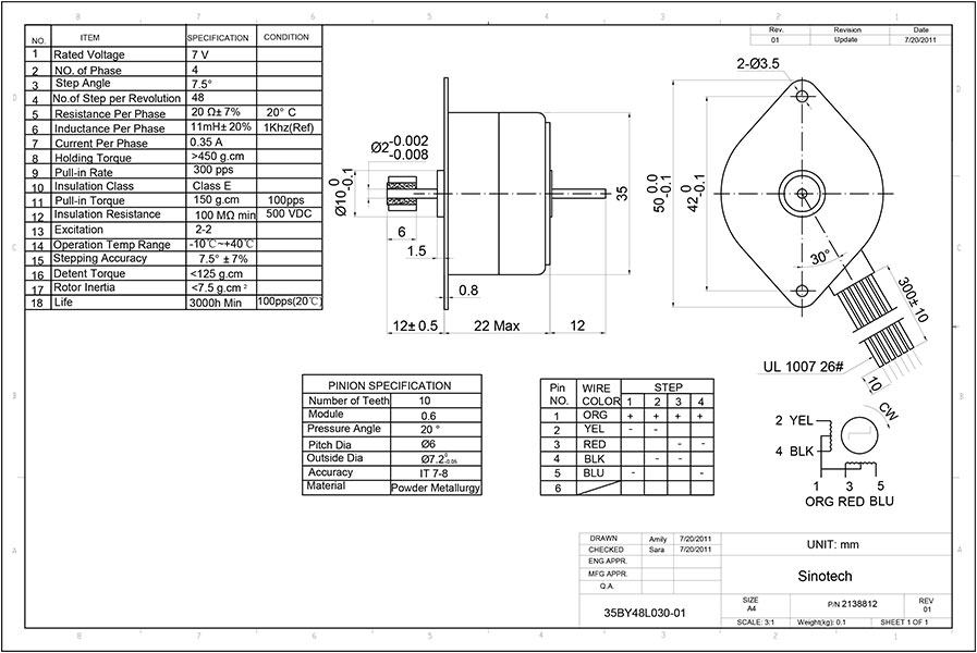
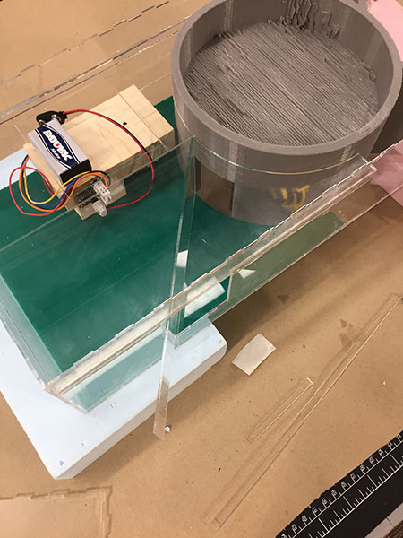
The First Motor:
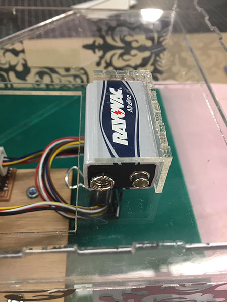
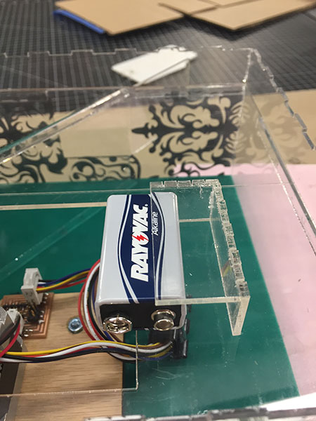
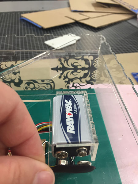
The Battery Holder:
I wanted a secure yet easily removable place for the battery to sit so I built a small box that would attach to the removable wheel holder/back clear panel. As you can see below you can easily slide it up and also attach the 9V connector to the circuit board.
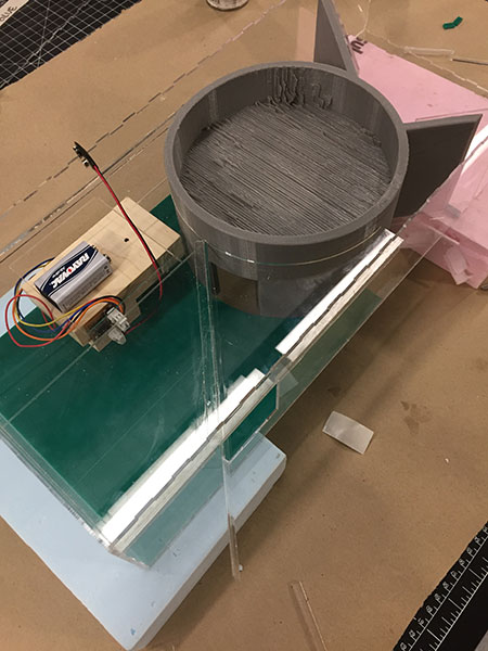
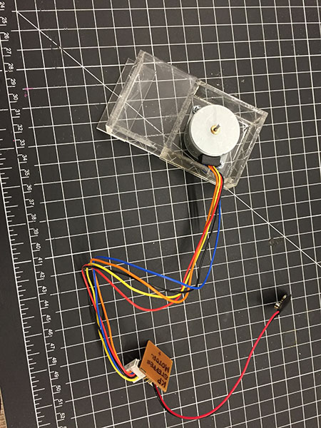
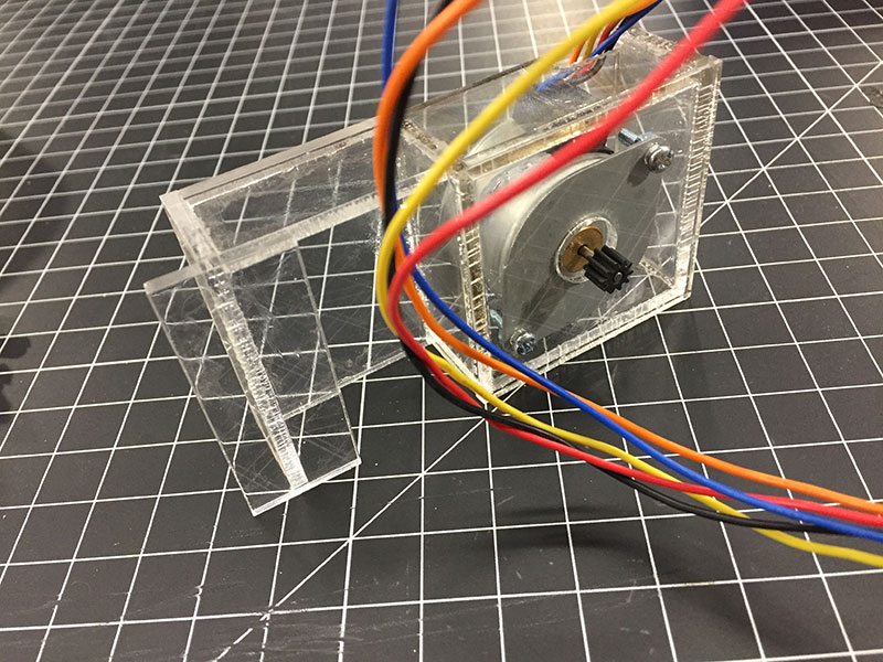
I realized at this point that the 7V motor was not going to be enough (or what I wanted) to move the Kitty Matic. I upgraded to a 12 V ----I also created a "motor holder" for the motor and the board to be attached to. This helps with the movement of the motor and with design/ease of removing these items if need be.
Working towards the finishing steps:
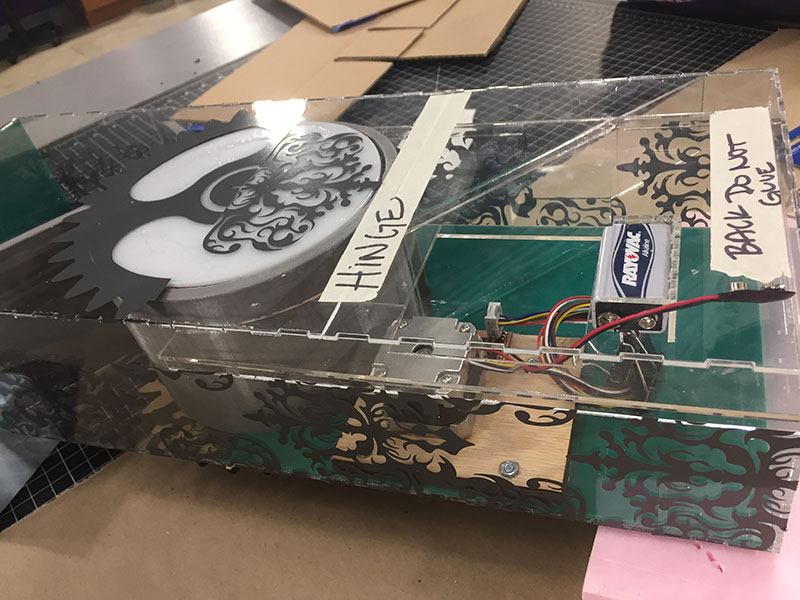
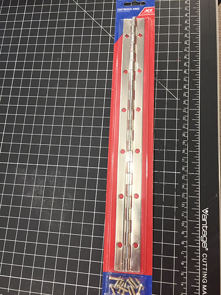
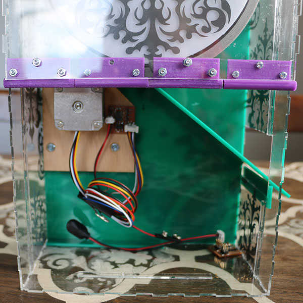
With most of the actual machine intact and put together I needed to find and attach the hinge to the back of the machine so that the battery and the motor/mechanics would always be easy to get to.
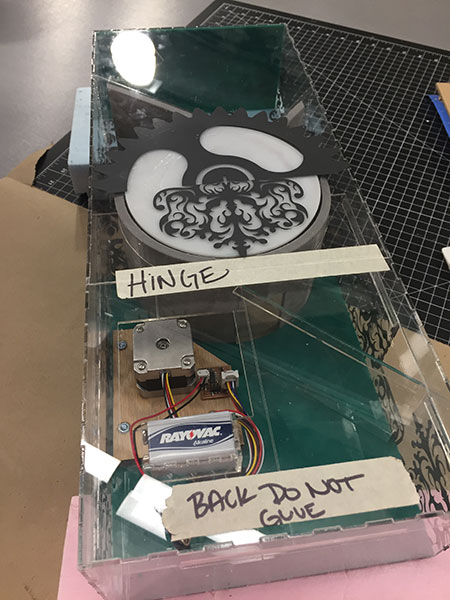
I chose a piano type hinge in silver to help with design and function.
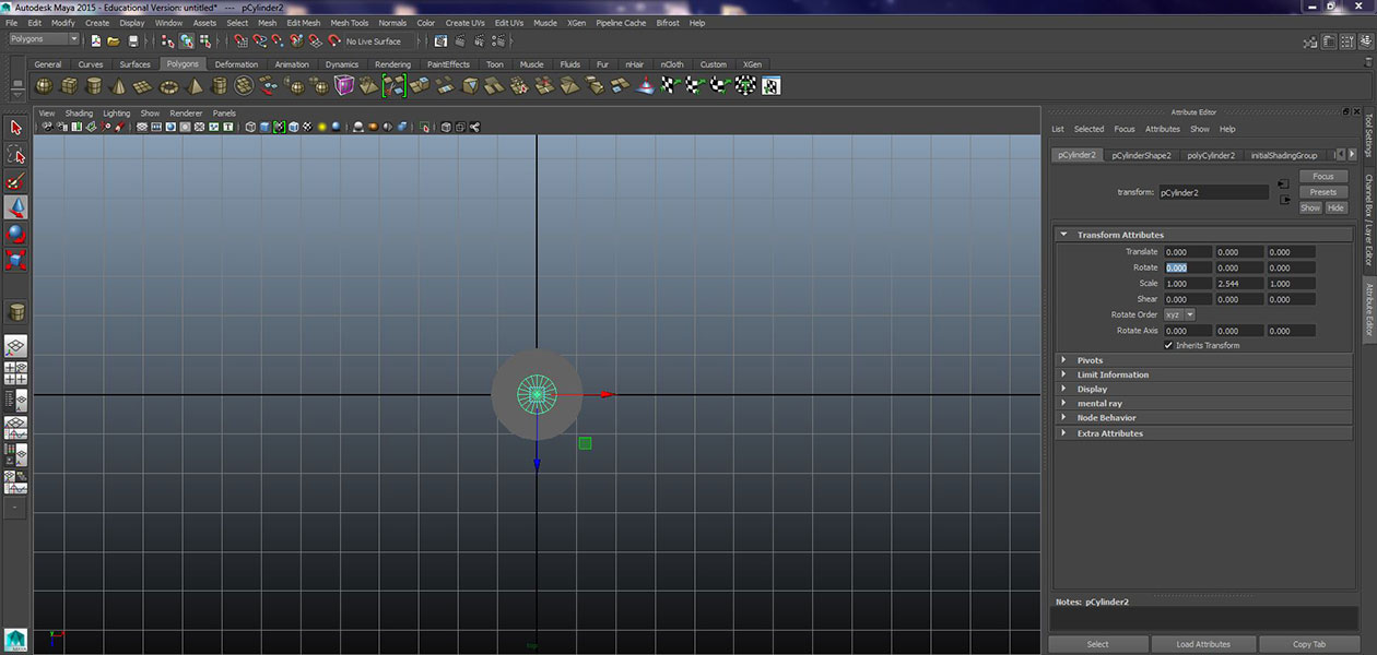
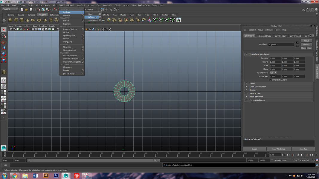
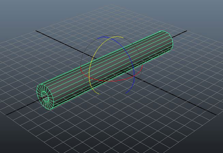
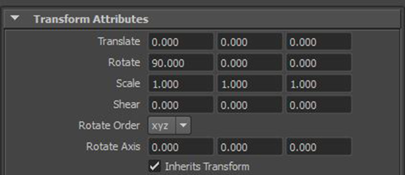
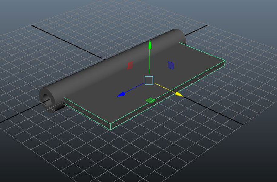
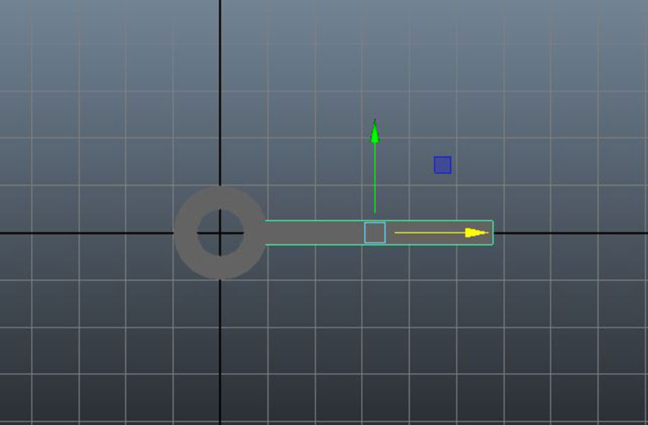
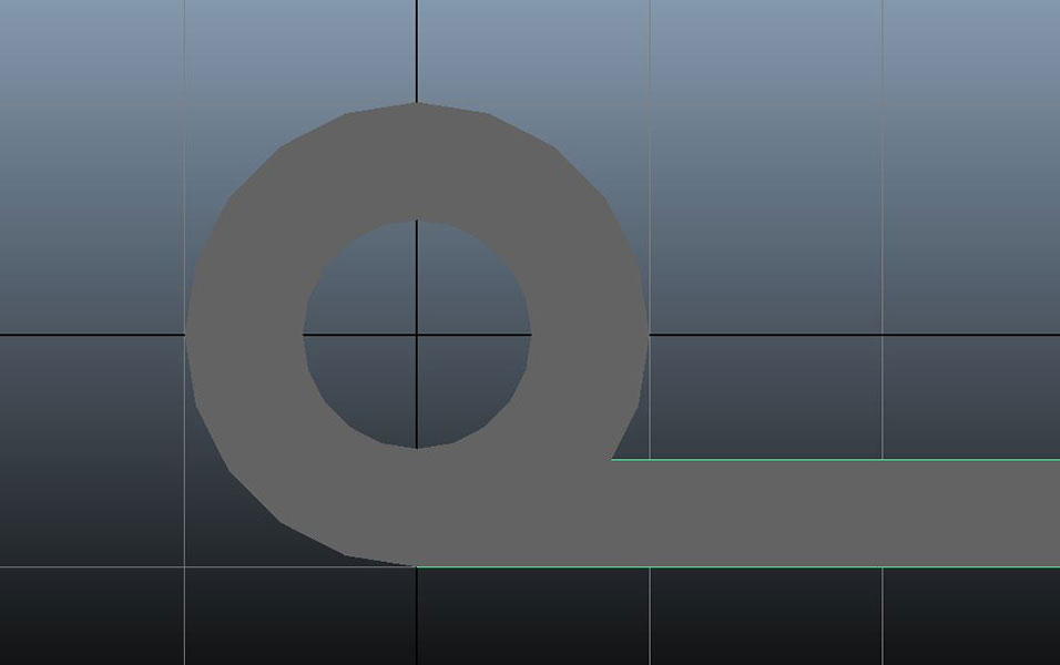
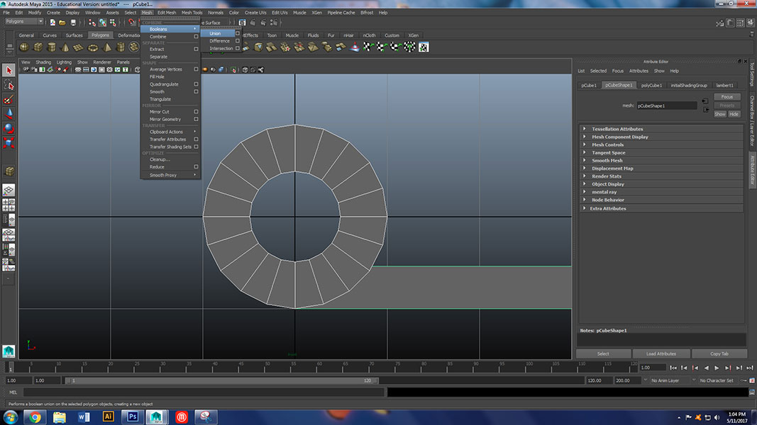
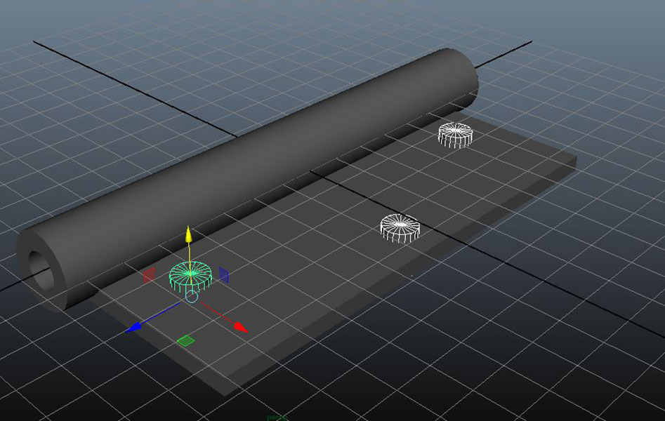
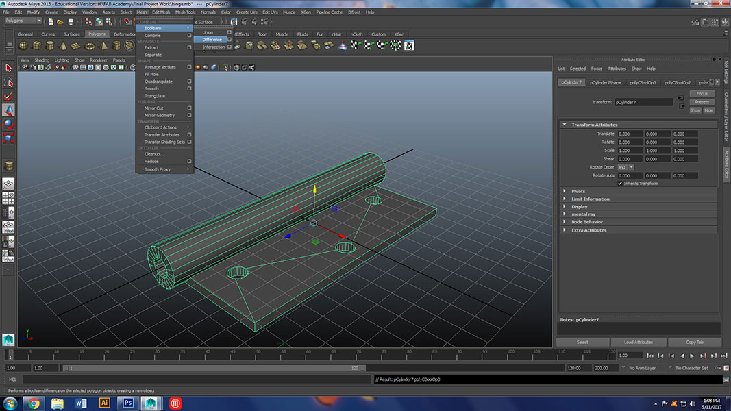
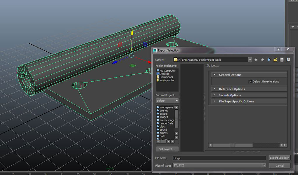
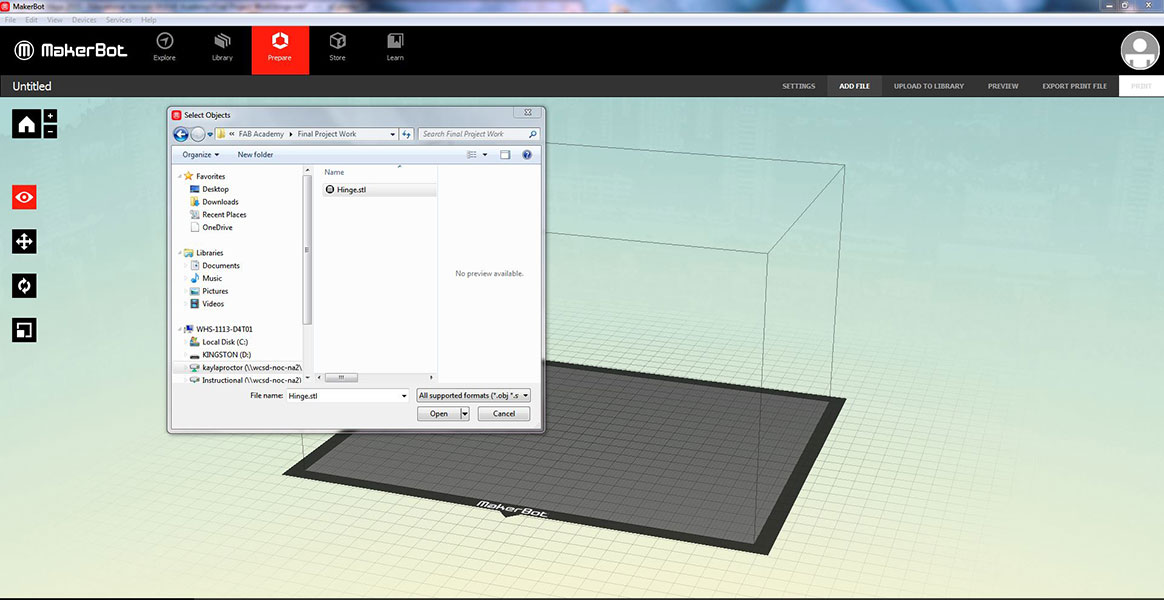
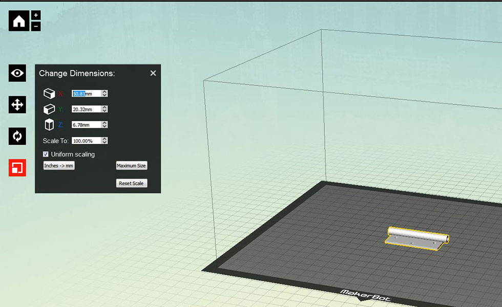
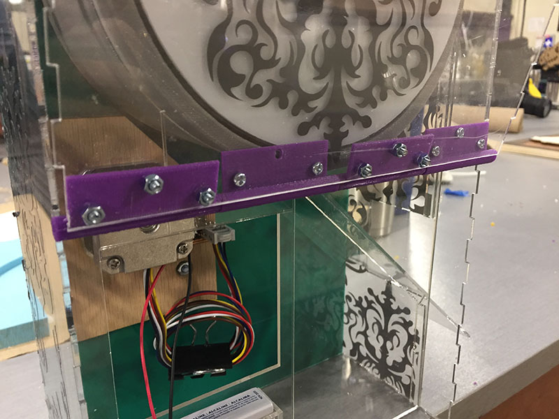
I then realized that I could probably model and 3D print a hinge as well. So I did that! I used Maya to model the part and the exported as an STL and set it up in the Makerbot software and printed 4 of them.
I then used a metal rod to place them on it that did not bend and then attached them to the acrylic.
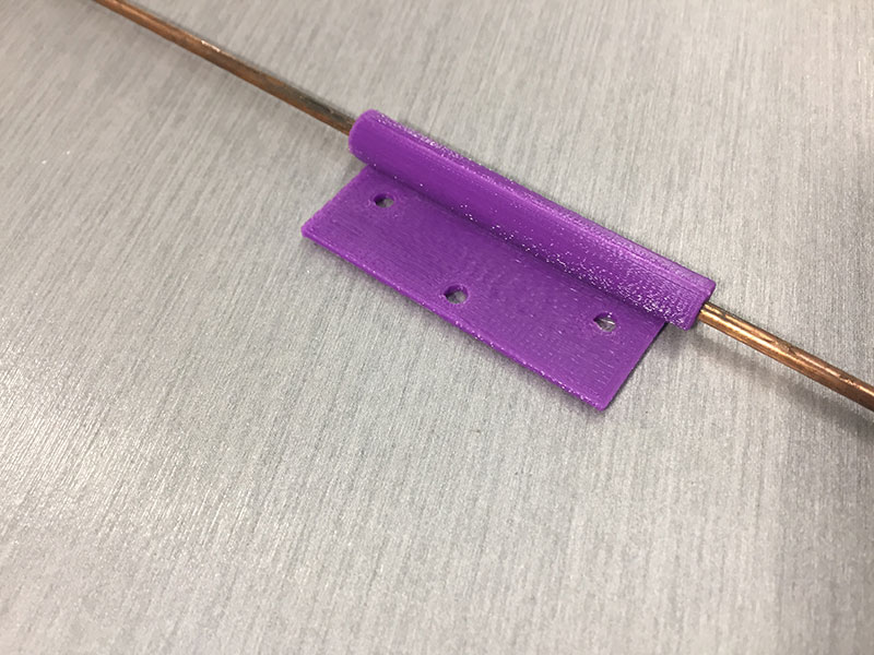
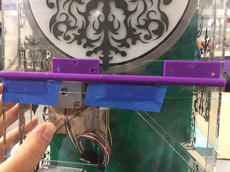
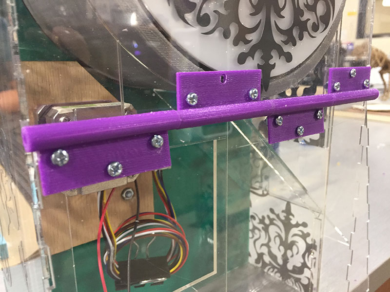
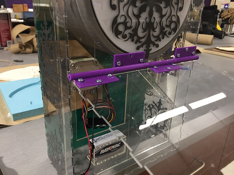
I used bolts with nuts on the other side to keep the hinges secured to the acrylic.
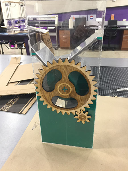
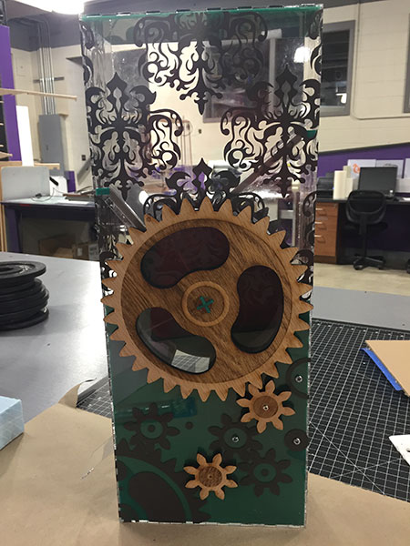
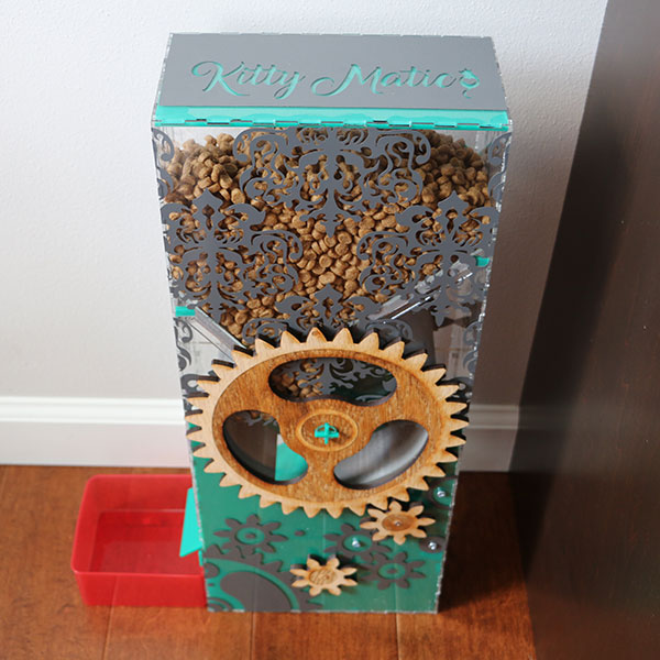
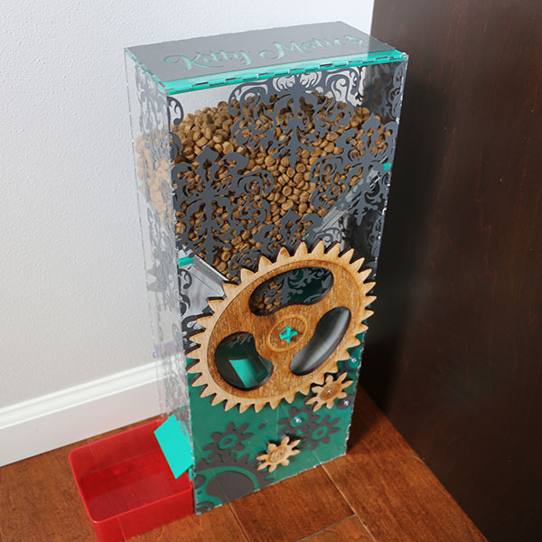
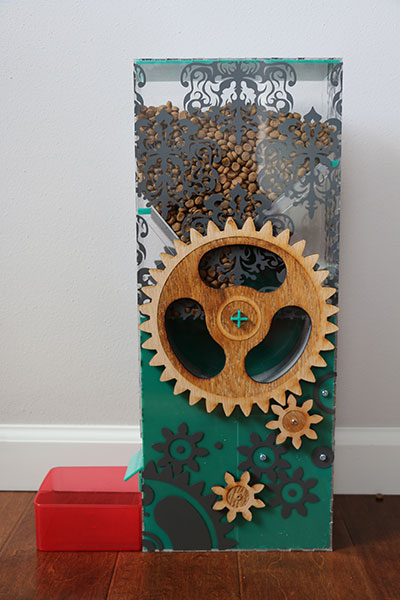
As you can see below design is a big thing for me. I wanted to make sure that the machine was asthetically pleasing along with functional. I designed all of my decals in Illustrator and cut them with our vinyl cutter. I also engraved the wood along with cut it out with the laser to have a two tone look to create interest to the viewer. There were also a few places that I used a teal acrylic instead of clear to block the viewer from seeing things and to add contrast to the machine.
Working on Programming:

This is what happens when using the program from week 10 - output on the motor. I am currently working on writing a new C code to turn the motor 90 degrees every 12 hours.
Testing/writing code for the Kitty Matic:
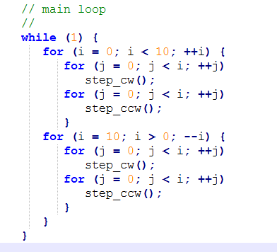
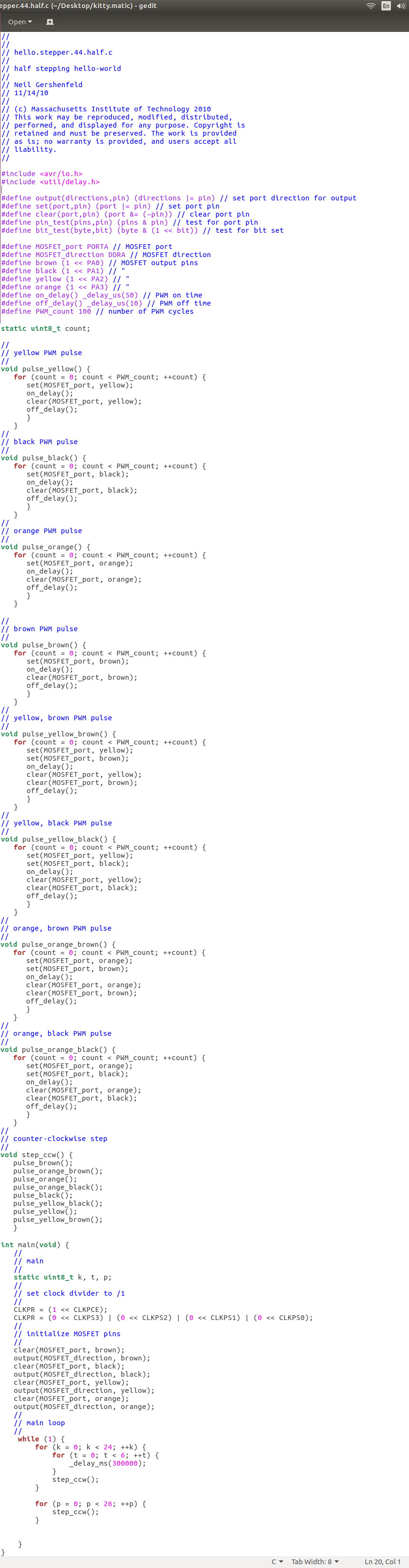
I started by using the c code for the stepper motor that was provided for us:
hello.stepper.44.half.c
I did A LOT of testing as I have little to no experience with coding, so the process was long and all over the place.
I started with editing the main loop.
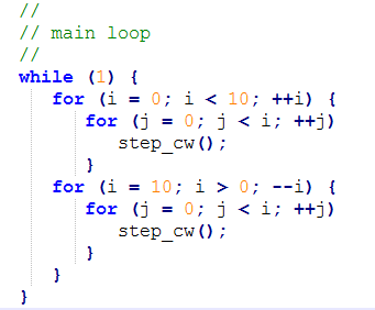
I needed the motor to turn clockwise so I took out the step_ccw(); from both lines.
Since I am using the same board as I used in week 10 I made a duplicate for testing purposes. I am also using the same files on my Linux computer so I just copied them into a new folder/directory called: kitty.matic
I then opened the terminal and typed: cd ~/Desktop/kitty.matic, then: make (made sure my make file included the atmel_ice as usual), then: make program-ice
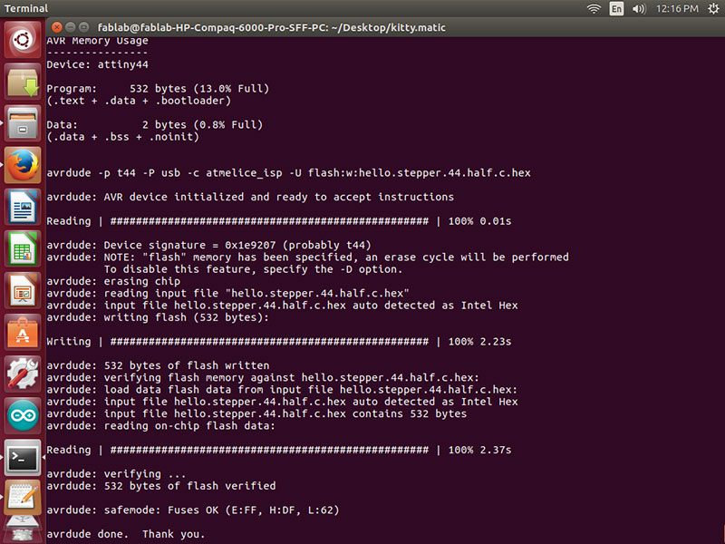
I made sure to unplug the power before disconnecting the programmer and then plugging in the motor. Then plugged back in the power. I was excited to see the Kitty Matic motor/wheel turn…it worked great….except it was going the wrong direction!
So back to the programing. And this time I took out all of the step_cw();
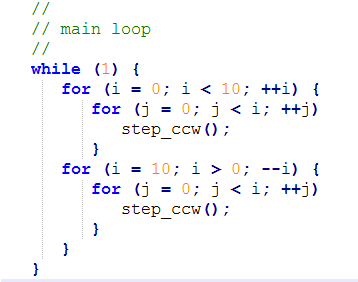
This was a success.
Then it was on to trying to figure out how to change the “//main loop”. So I pretty much started from scratch. I tool out the i/j. The “for” loops variable were to count and not needed yet. Frankly I didn’t understand them either so it was good to start at the bottom and work my way up. I also removed the line: stratic uint8_t i, j; where they were defined. Then I made sure the loops were closed with the { } brackets back in the right places.
I had a friend helping me at this point that has done coding in other programs before just not C, so this was a great help because they understood the process at least.
We tried adding #include <stdio.h> and put sleep(2); in the loop. This didn’t work.
We then tried #define off/on delay (1000) to see it move more slowly. It was great to see a change, but I didn’t need it to be slower….so we changed that back.
![]()
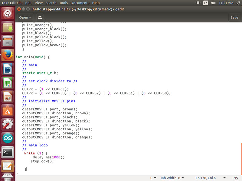
Then we moved back to the loop added _delay_ms (1000); which by changing the delay to ms we were using milliseconds instead of us which is microseconds. Then we tried (2000) and then (12000) – 1 second, 2 second, 12 seconds between each step. This was fantastic! Finally getting to stepping the motor in a controlled way.
This is when we realized we were going to need to put back in the line stratic uint8_t i, j; and start to define variables in the main loop. Since this is the Kitty Matic and my name starts with a K, I decided that should be our first variable. stratic uint8_t k;
With the 1 second test we counted how many steps the motor took to turn 90 degrees. It was 50.
Some of the things I learned about code:
The “while” loop runs forever when closed {}.
“while (1)” is always true.
The “for” loop k < (50) will step the motor 50 times.
K < (50) will step 90 degrees.
_delay_ms (10000) is 10 seconds.
At this point we got the Kitty Matic to turn the 50 steps and then stop at 90 degrees to feed!
We used the code below to try to make the Kitty Matic turn 1 tick every 4 hours with a full dump of food at 12 hours.
Here is the math:
_delay_ms(30000) delaying 30 seconds
There are 3600 seconds in an hour.
3600 x 12 hours = 43200 seconds in 12 hours.
43200/30 = 1440 delays of the “for” loop @ 30 seconds
Our first 12 hour test was coded with 10 seconds of delay – 1440 times before it turned 90 degrees (50 steps).
In theory this would have worked, but after being plugged in from 6:35 pm – 6:35 am I was very disappointed. It seems the clock on the attiny44 did not like the waiting.
So now that I understood code a bit more, and the brackets and how the parts really come together I went back to the drawing board.
I did many tests on time, to see how long of time the motor and board could keep. I decided on 5 minutes. It kept pretty accurate time (only a few seconds off when tested over and over which wouldn’t matter in the long run for the cat feeder).
Test #1
1440 times at 10 seconds. Failed
Test #2
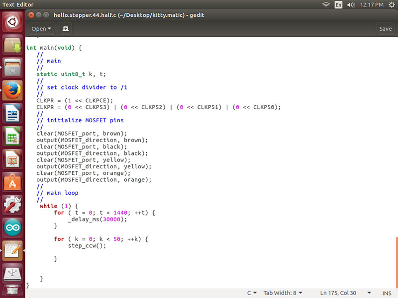
I added a variable which was t and added another “for” loop.
t < 6 and then the delay was (300000) roughly 5 minutes = 30 minutes
This worked! Success. The motor moved at 28 minutes and 40 seconds time and time again. I left this running over night and it was still running in the morning.
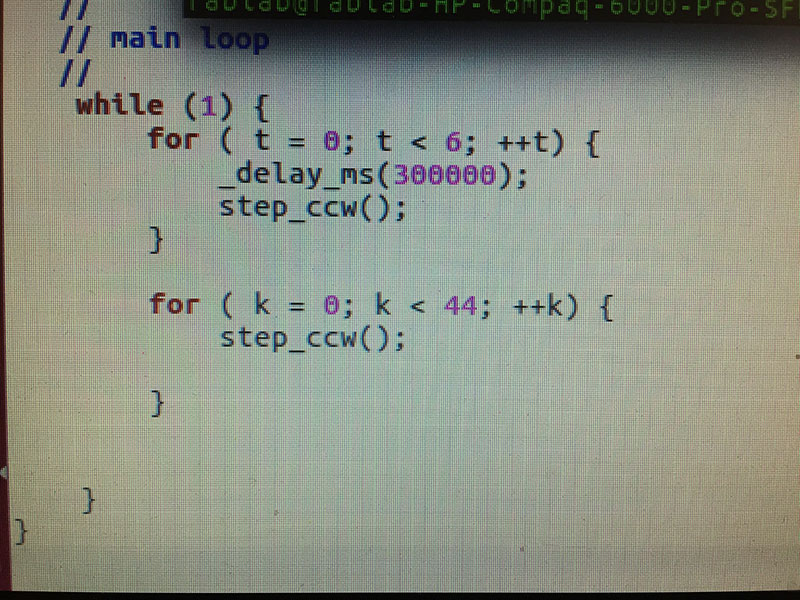
Test #3:
This time I wanted to see if I could get the code to step once every 30 minutes (to see progress) for the 12 hours (24) and then at 12 hours step the other 26 to complete the 50 (90 degrees) and feed the cats.
Code 1 - WRONG 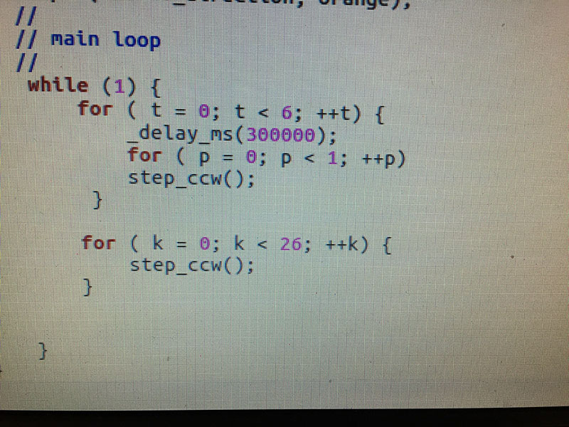
Code 2 - WRONG
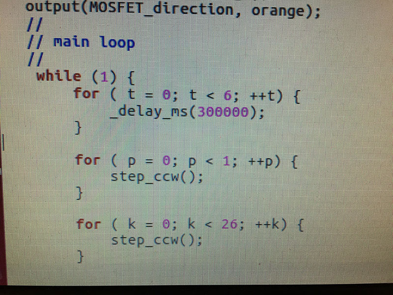
Code 3 - CORRECT!!
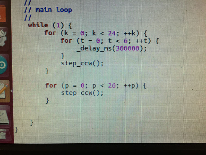
TEST 3 WAS A SUCCESS!!!!
The motor stepped once every 30 minutes as coded. Then after 24 steps (12 hours) it stepped 26 times to complete the 50 steps (90 degrees). The cat feeder is complete!!
Here is the complete file for the c code.
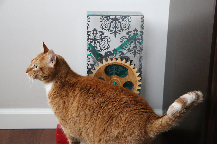
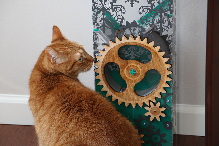
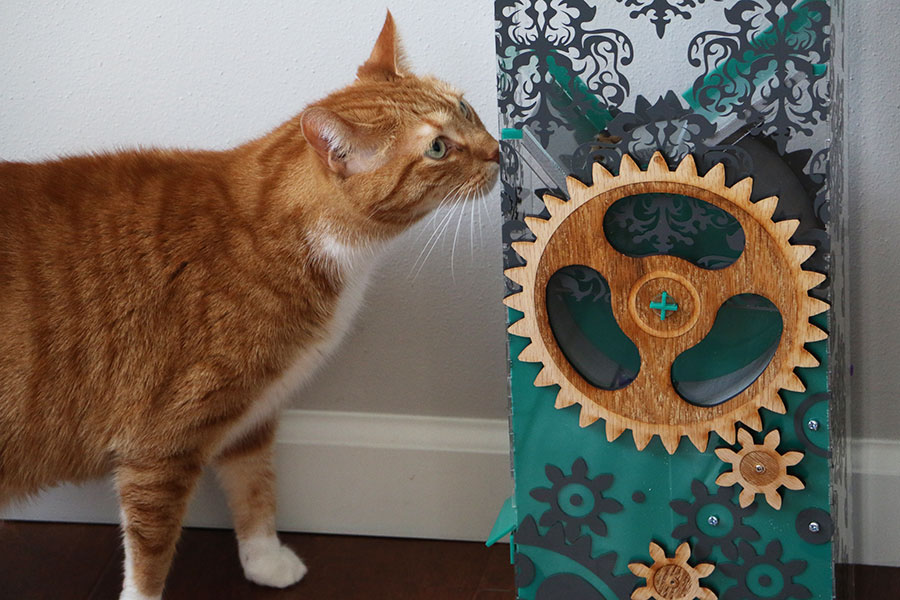
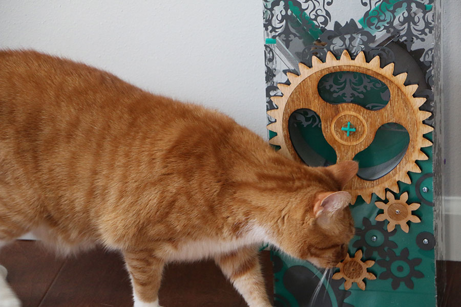
And some final pictures of the kitty with the Kitty Matic:
Adding a button for manual feed option:
In review it came up that I needed an input device. Adding a button for the Kitty Matic to have a manual feed option was suggested and a great idea. Through much trial and error I have completed the task!
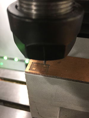
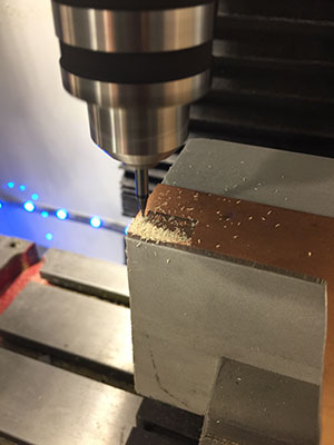
First - Making the Button:
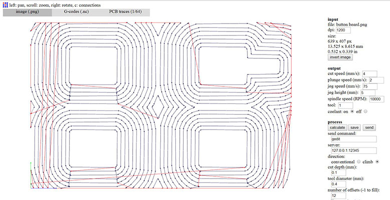
I used a previous png and altered it in photoshop to fit the needs of my button. I then made the outline and uploaded to fabmodules.org to get the g-codes for the mill. For the button board I ended up using 12 traces to cover the FR1 and make only the copper button spaces left. Then I did the outline file.


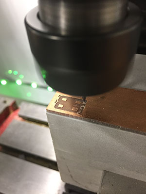
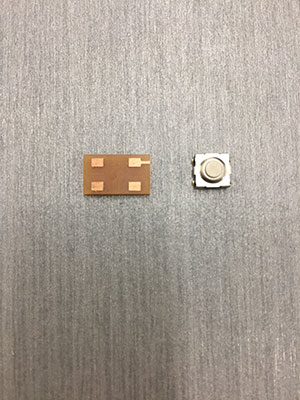
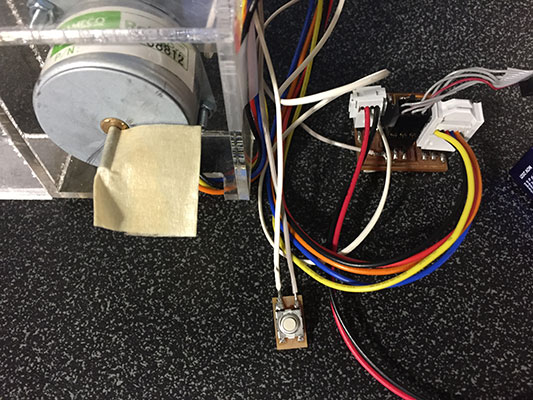
I then soldered the button to the pad that I milled.
I looked at my board and found that PA7 was open on the attiny44 so I connected the button to that pin.
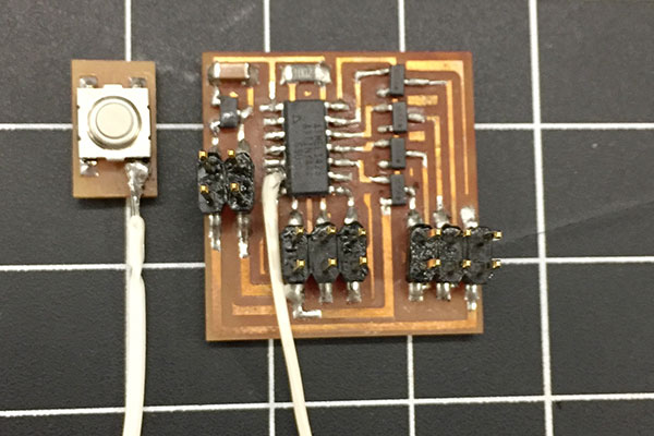
Then the button needed power. I found that I could connect the other side of the button to the "power" where my trace "GND" went to the battery connector. I soldered that connection as well.
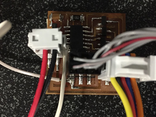
Connected to my Atmel Ice, power and test motor.
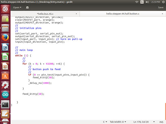
Made a copy of the code I had been using and called it hello.stepper.44.half.button.c and changed the makefile to reflect that. Then as I worked with the files I continued to rename them and save them in a different location but while flashing the board continued to use the hello.stepper.44.half.button.c name.
There were many changes that I made to the code after that. There are files and videos that go with those changes.
hello.stepper.44.half.button.c down 1 up 10 - video 1
hello.stepper.44.half.button.c two codes together
hello.stepper.44.half.button.c 10 second auto 50 button for manual 5
hello.stepper.44.half.button.c 12 hours with manual button feed final
Adding in the feed_kitty(int steps) simplifies the code and helps with the
for and if code.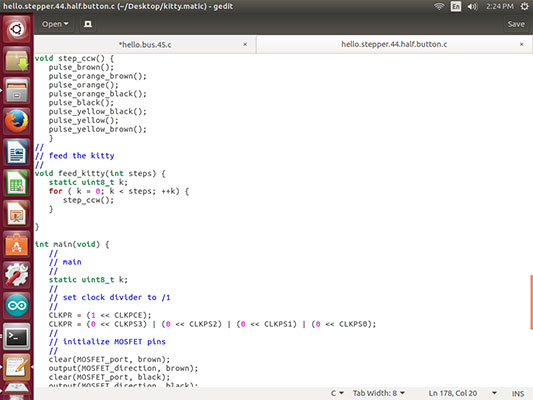

Kitty Matic by Kayla Proctor is licensed under a Creative Commons Attribution-NonCommercial-ShareAlike 4.0 International License
The MIT License (MIT)
Copyright (c) <2017> <Kayla Proctor>
Permission is hereby granted, free of charge, to any person obtaining a copy of this software and associated documentation files (the "Software"), to deal in the Software without restriction, including without limitation the rights to use, copy, modify, merge, publish, distribute, sublicense, and/or sell copies of the Software, and to permit persons to whom the Software is furnished to do so, subject to the following conditions:
The above copyright notice and this permission notice shall be included in all copies or substantial portions of the Software.
THE SOFTWARE IS PROVIDED "AS IS", WITHOUT WARRANTY OF ANY KIND, EXPRESS OR IMPLIED, INCLUDING BUT NOT LIMITED TO THE WARRANTIES OF MERCHANTABILITY, FITNESS FOR A PARTICULAR PURPOSE AND NONINFRINGEMENT. IN NO EVENT SHALL THE AUTHORS OR COPYRIGHT HOLDERS BE LIABLE FOR ANY CLAIM, DAMAGES OR OTHER LIABILITY, WHETHER IN AN ACTION OF CONTRACT, TORT OR OTHERWISE, ARISING FROM, OUT OF OR IN CONNECTION WITH THE SOFTWARE OR THE USE OR OTHER DEALINGS IN THE SOFTWARE.