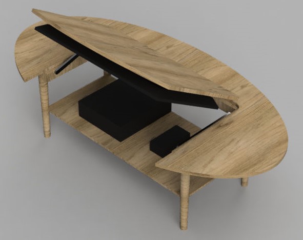
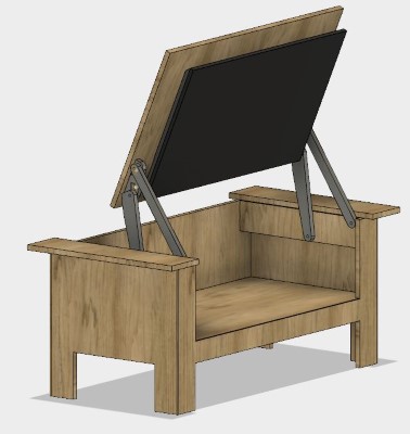
I want to make the foldable coffee table that I drew in week2. I want to use it our living room at home. I also hope to turn this into a product.
When using a CNC milling machine feeds and speeds matters.
The speed refers to how fast you spin the spindle, measured in rotations per minute (RPM) and the feed refers how fast you move the spindle over the material, either measured in milimeter per second (mm/s) or milimeter per minute (mm/m). The combination of your choice of milling bit, feed, and speed values will determine how big bites your milling bit takes each time it digs into the material. This bite size is refered to as feed per tooth, also called chip load and it is measured in milimeters (mm).
Excellent resource for CNC operators
If you go to slow the milling bit will rub against the material instead of cutting it, the rubbing friction generates lots of heat very fast and depending on the material you might break the bit, melt the material or even set fire to it!
If you go too fast you basically are trying to take too large bites with each cut. This will create large forces on your machine, which you will hear! Pay attention to the sound! These increased forces will first bend your machine and bit slighly, causing it to mill slightly of target, then it will cause vibrations that will leave ugly marks in the part and finally it will cause something to give. Most likely your bit will break but with a weak machine your motors might stall before that happens.
The depth of cut is how deep into the material your bit is as it moves through the material. How deep you can go depends on your machine robustnes and power as well as how thick you bit is. Deeeper cuts equals larger cutting forces on the bit, the frame of the machine, its axis motors, and the spindle. Going too shallow is not a big problem but will make your work take much longer than necessary.
"What goes in must come out" is also true for your milling bits. They will have some kind of "fluteing", that is one or more flutes (often twisted channels) ment to remove the chips of material as they are being cut from the stock. If you have small flutes and make the machine take large bites with each cut you are likely to clog your bit resulting in, you guessed it, a broken bit.
So how to find the prefect setting then?
Some things will be generic and some things will be machine and material specific so to get started it is a good idea to use someone elses tried and tested values and start from there. I got this recommendation from Jens to start with:
Source: Instructor Jens Dyvik Dyvik Design Fellesverkstedet
If your machine uses a different spindle speed (shopbot typically uses 18000 RPM) or if you want to try a different type of bit then you need to adjust your feed speed so that the bite-size, (also known as chipload or "feed per tooth") stays the same.
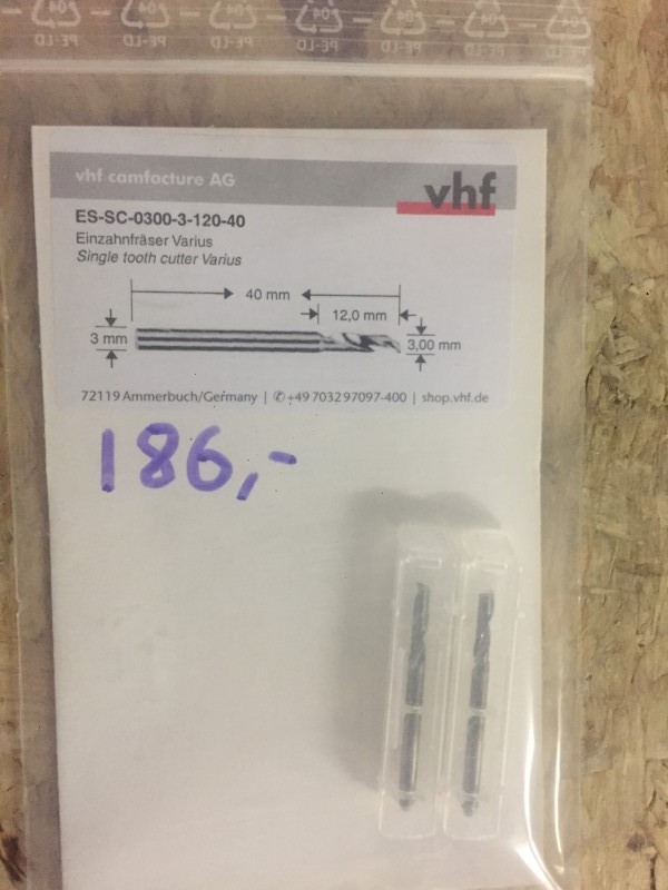
Example:I have used this 3 mm single flute upcut flat endmill carbide milling bit from VHF.
I have not been able to find manufacturers values for optimal chip load for this tool so let us calculate one from Jens recommendations.
To repeat: We have a 3 mm diameter bit with one cutting edge. (Single flute.)
We spin it 24000 rotations per minute, that means we do 24000 cuts per minute with our single cutting edge. If we had a two flute bit, we would have done twice as many cuts.
We move it sideways 35 mm per second or for simplicity 2100 mm per minute (35mm/s*60s=2100mm/minute).
How big bites does the milling bit take each revolution? That will be our chip load. (Feed per tooth.)
2100 mm/min / 24000 cuts/min = 0.0875 mm / per cut = chip load.
We can now use this chip load value to figure out starting values for when we are using different bits or spindle speeds.
Example: A 3 mm bit with two flutes, what should our feed be if we use the same spindle speed?
If we had good results with our machine using the settings that gave us the 0.0875 mm chip load above. Then we should be getting similarly good results using a two flute bit if we make it have the same chip load. We might still get other new problems like flute clogging with this new bit but this will give us a starting point.
24000 revolutions per minute times two cutting edges means we will now be cutting 48000 cuts per minute.
If we take the chip load of 0.0875 mm / per cut times 48000 cuts per minute we find that we need a feed speed of 4200 mm / minute. (0.0875 * 48000 = 4200). Note that this means we use twice the feed speed for a two flute bit compared to what we used for our single flute bit to take the same size bite with each cut. Logical right?
Chip load = Feed / Spindle Speed * Number of Flutes
You can use this to translate between different number of flutes and different machince capacites. When it comes to finding out how much your machine can take you need to be willing to risk a few bits while testing deeper and deeper cuts and larger chip loads. Wear protective glasses, remember to make and publish your notes and have fun!
I got a 16 mm thick 2500mm*1240mm plywood sheet with 0,5mm white oak veneer on the sides.
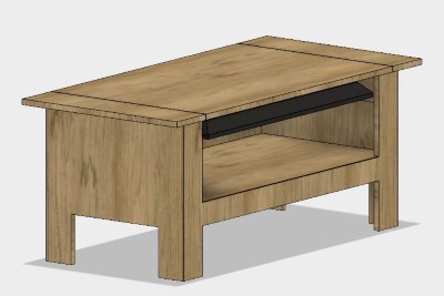
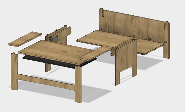
I needed to change my design to reflect using sheet stock instead of planks. I'm much better at making something functional that something estecially pleasing so I anticipated that this would be a challange. I'll used the deadline to push myself to settle for a design but trying different looks still took three days!
This is the TV and the living room I will put the table in. The wooden box on the floor is a placeholder for the table.


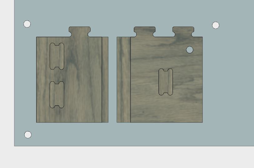
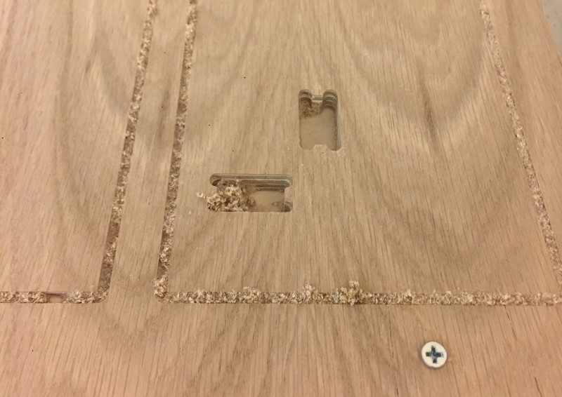
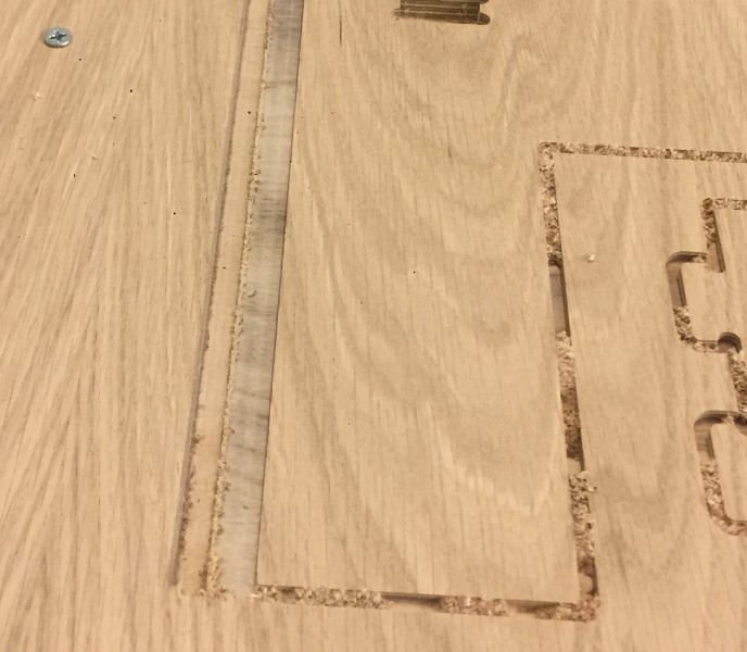
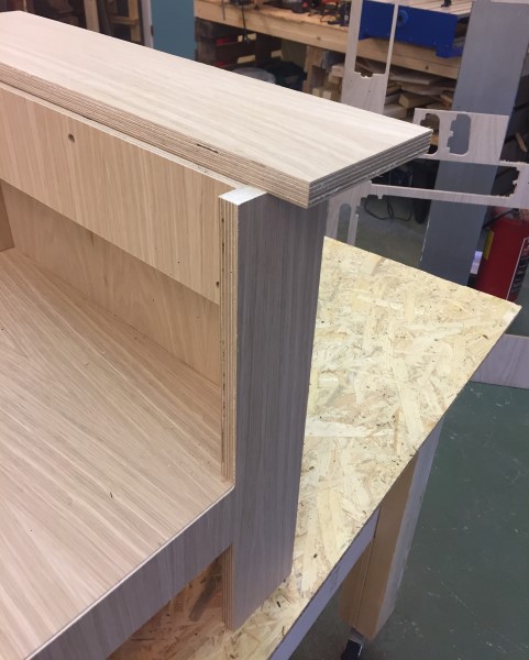
I added tounge and groove joints for press fitting the sheets to each other. I cut the clearances for the fitting with this body, it has 2*0,2 mm margin to the width/material thickness direction and 2*0,1 mm for the length.
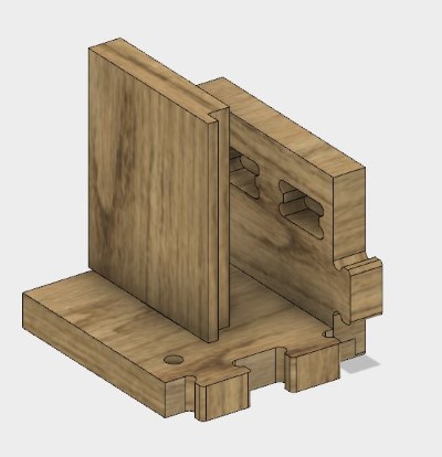
Made sure it fits my material stock
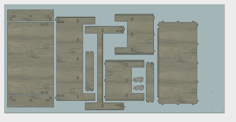
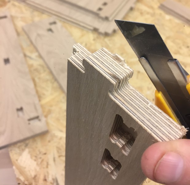
Designed two test pieces including all my critial joints
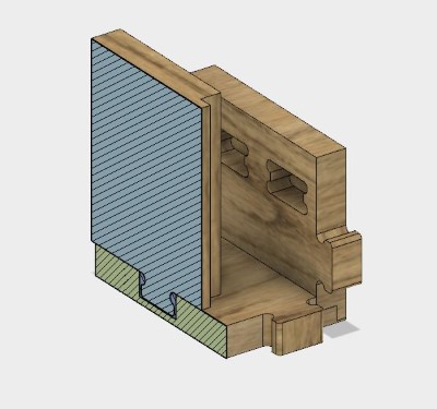
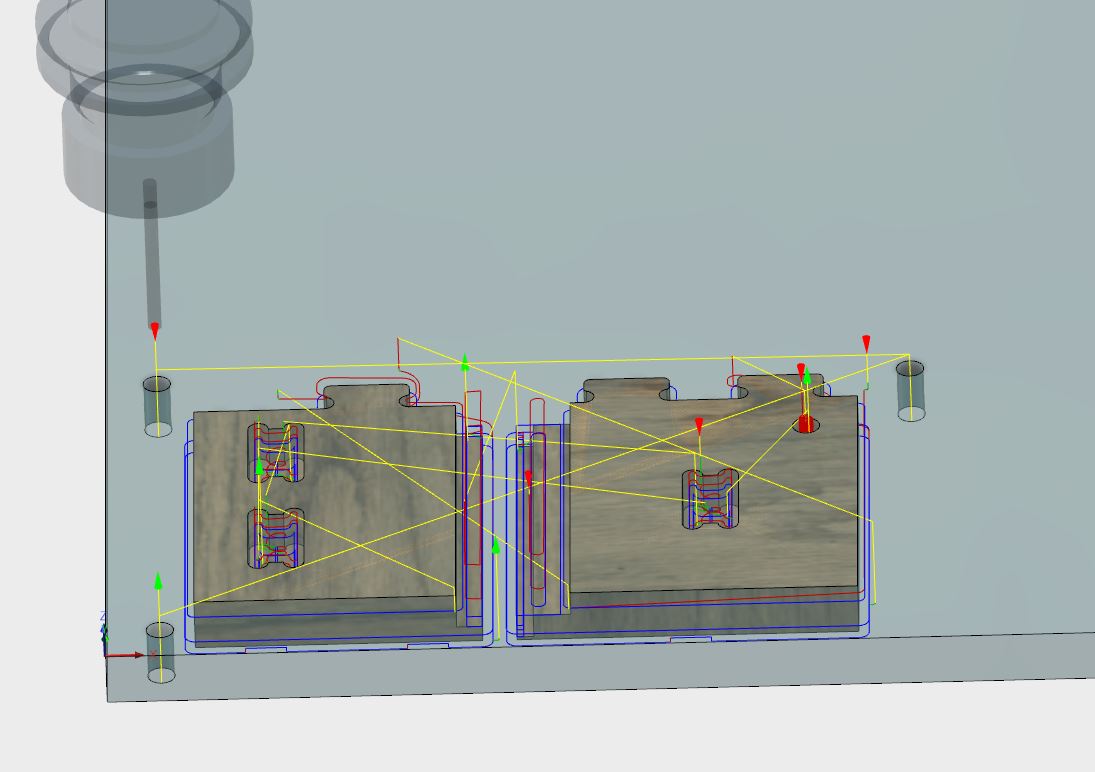
Designed CAM programs for them, using both up and downcut bits
1.jpg)
1.jpg)
1.jpg)
1.jpg)
1.jpg)
1.jpg)
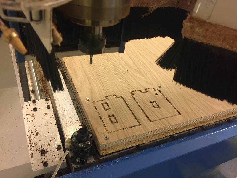
Success! Supricingly no tweaking needed, the tounges slide in easily and stick in the bottom. Probably due to some happy accident with bit deflection.
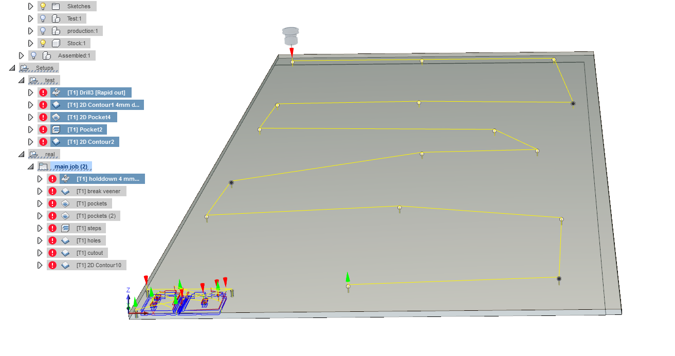
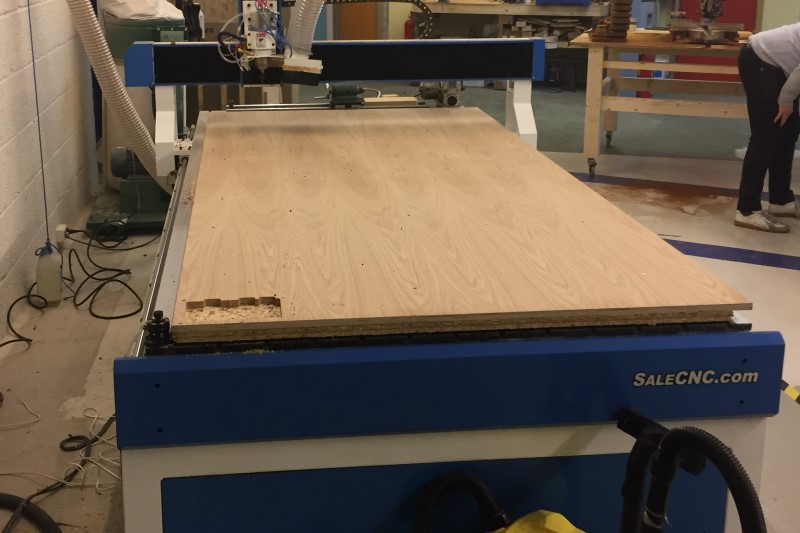
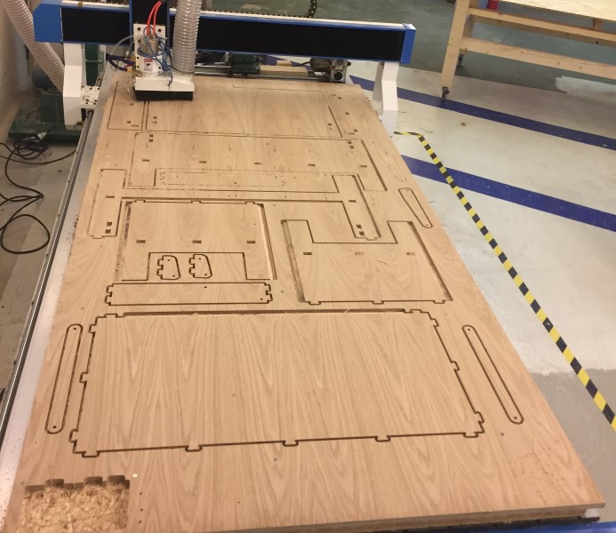
Time to mill the big job!
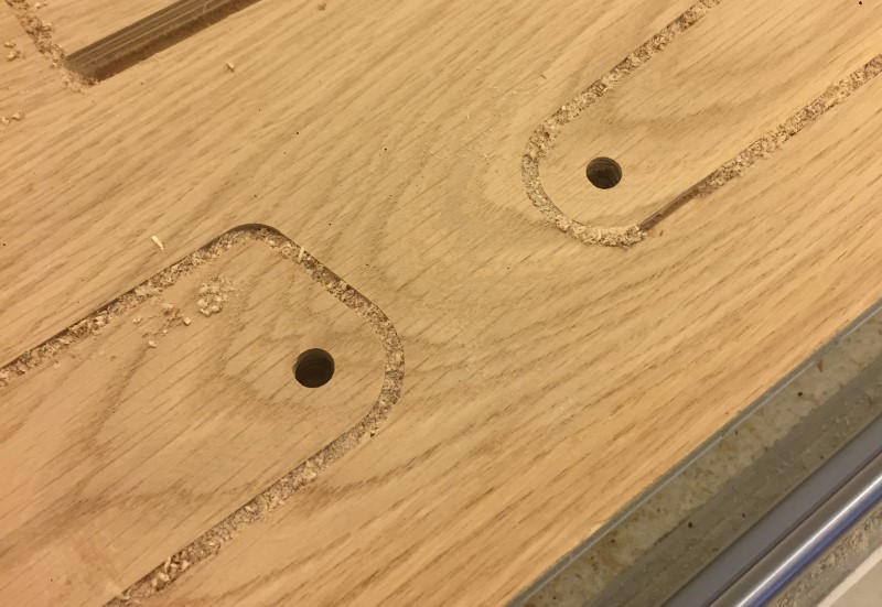
I set up hold-down holes to be drilled by the CNC to avoid any risk of the milling bit later colliding with my hold down screws. I milled a 4 mm clearance hole for each screw to get a good hold down force from the screws.
I counted the holes in CAD and took out as many screws as I have holes so that I shouldn't miss to fill any holes. I stood on the board and added the screws from the middle out.
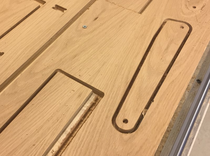
Breaking the to veneer with a downcut bit to avoid damaging it with the up-cut later.
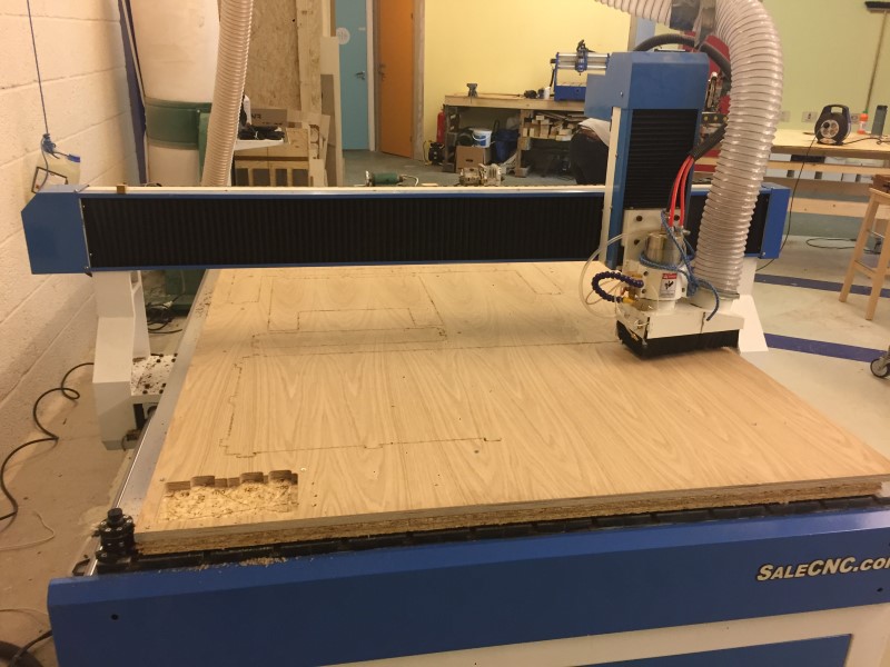
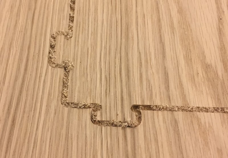
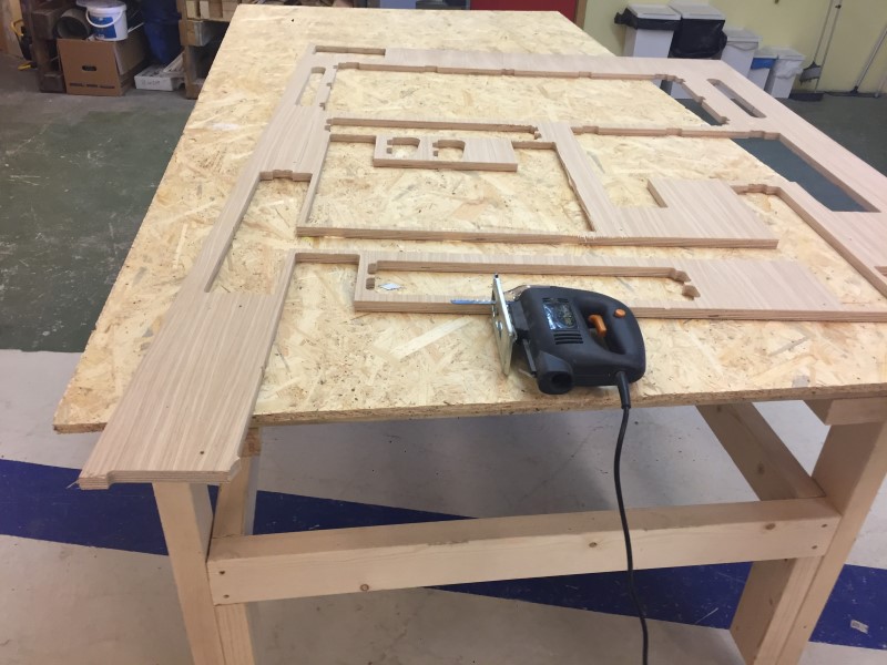
Cutting the (2D) pockets with the upcut bit.
I had to use a 3D pocket operation to get these to compute correctly. The fusion 360 CAM engine seems to ignore the stock when doing open ended 2D pockets. Making it impossible to force a ramp or helix, it just plunges. Possibly there is a way to get it working, but I ended up using a 3D pocket which worked fine if you add your model in the "SETUP" operation.
Drilled the holes in a separate operation to get fine control of the ramping.
I left tabs a what I though was strategic, hidden places, I was almost right... Got some damage in a visible place when I missed cutting one.
Cutting the tabs
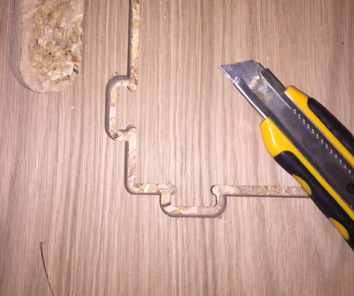
Cleaning up the edges
The skeleton of the sheet
Scrapped it with a occilating saw to save space and recove some spare material.
Reusable material for spare parts.
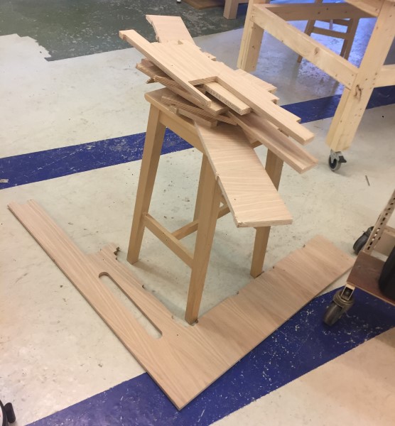
Scrap! Not much :)

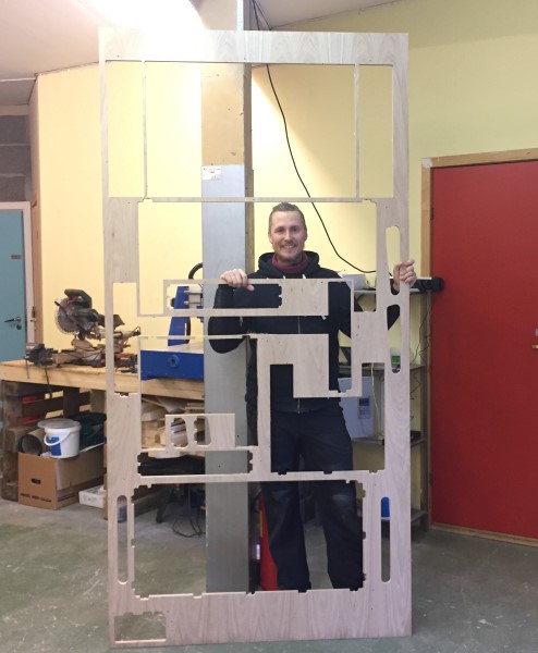
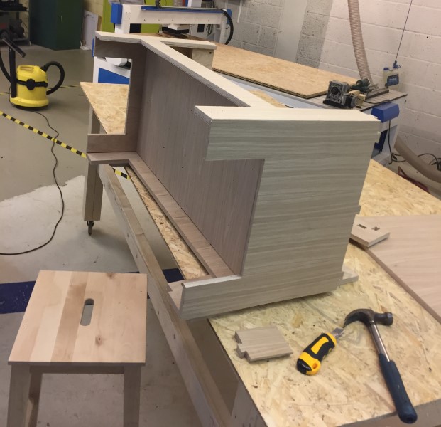
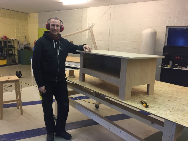
Time to assemble! (without glue for now)
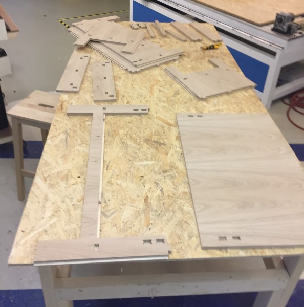
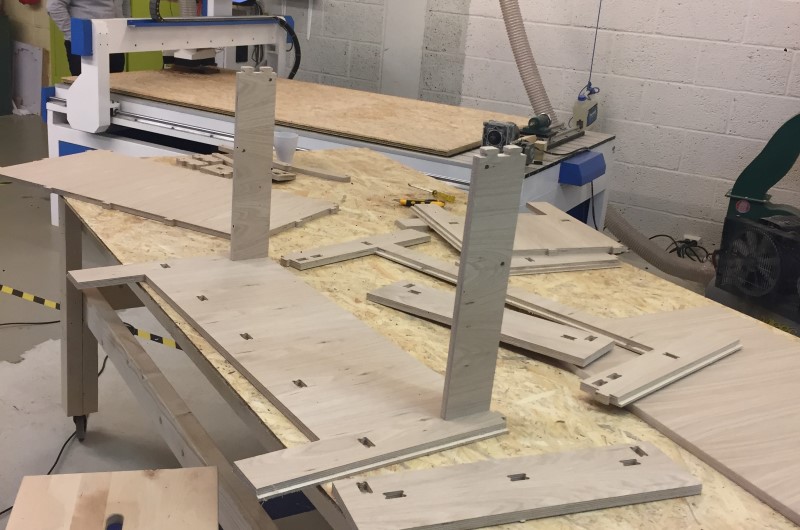
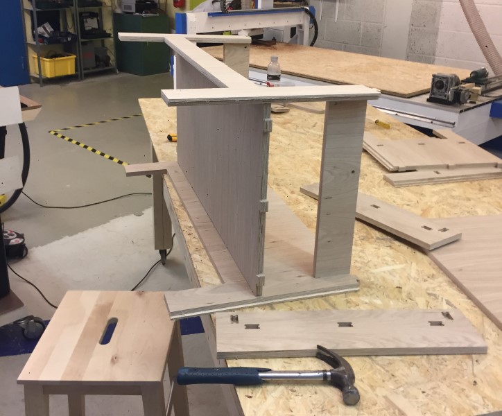
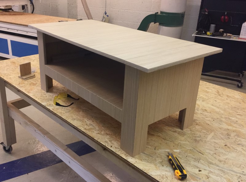
It fit together snugly when tapped with the hammer, no sanding required.
The test pieces was handy to soften the hammer blows.
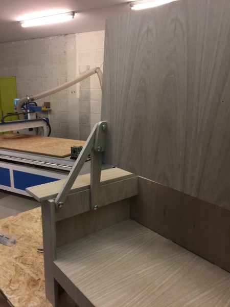
Found some 8 mm bolts so that I could teast my linkage.
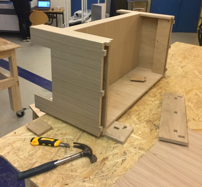
I assembled one piece upside down so I could only test one side this time.
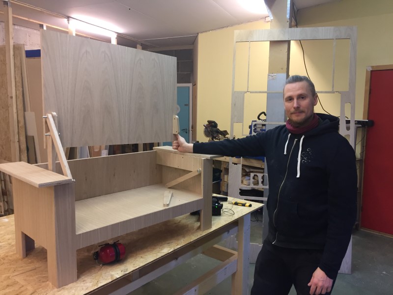
Happy fabber!
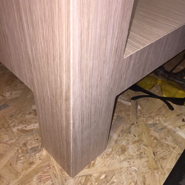
Some detail shots.
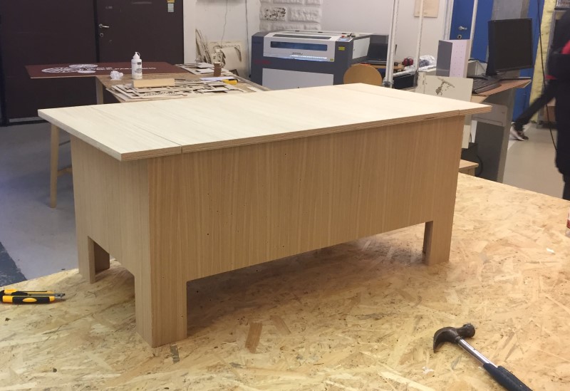
I am quite supriced how well it worked! Everything fit together very nicely and seems to work as intended.