And here we are at week 6, another week that talks about electronics and especially electronics design. So for this week we were assigned to redraw the echo hello-world board, add (at least) a button and LED (with current-limiting resistor) check the design rules, make it, and test it.
The first is to choose what software am going to use design my PCB, and the software I chose was Kokopelli, which is an open-source tool for computer-aided design and manufacturing (CAD/CAM),and it uses Python as a hardware description language for solid models. To download this software go to kokoretro and clone it. Before starting to install kokopelli there are some softwares that you need to download:
As I'm using linux manjaro I download all of these softwares from the Addsoftware:
Compiling:
- To compile, after downloading the list above, unzip fab_src.zip and cd to the folder which it's in.
- Type make fab, which should compile all executable and copy scripts into bin.
- At this point, make install will copy all executable and scripts to /usr/local/bin.
- Now you will have a folder for kokopelli that have the software and ready to use.
- To open the software go to the bin folder inside kokopelli folder and open the terminal and write this command python2 ./kokopelli -r
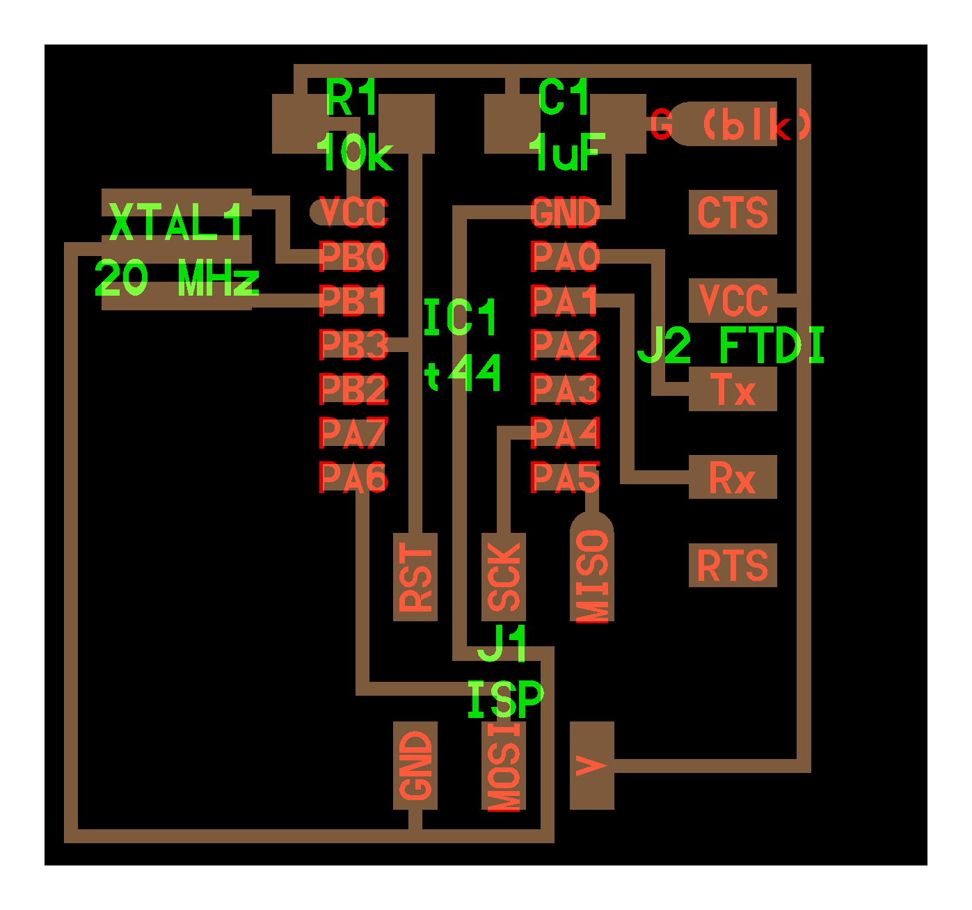
I prefer working with Kokopelli, so am using it for this weeks assignment and hopefully for the rest of the assignments that envolve designing a PCB. I started by taking the echo hello-world board:
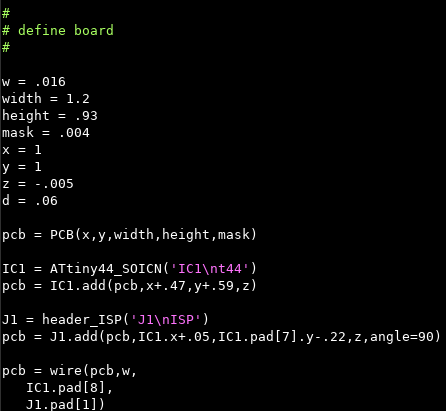
And then adding an LED to pin PA5 and a button to PB2, kokopelli have a set of libraries that defines common shapes and transforms, but you are free to change the designs to your own definition.So first under define board you will start by defining the board width, height and position, then after that you start by adding the components by using the package for example for the Attiny44 its ATtiny44_SOICN, regarding the text in purlple its the labeling that appears on each component in the board in green later, after that you position the components relative to the other components next to them and connect them togather, so in the case of the header J1 for example you type IC1.pad[8],J1.pad[1] which connects the pad 1 in the header to the pad 8 in the ATtiny44:
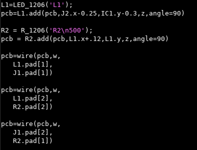
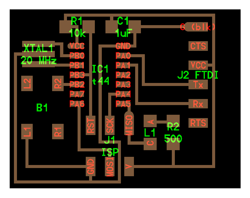
So now it was time to add the button and the LED to the board, regarding the LED that I used it has a 30 mA continues current and the Attiny44 output high is 4.3V according to the datasheet, so the required resistance will be 4.3/0.03 = 143 ohm so I used the resistor that is close to this value which we have in the lab which is 499 ohm and I connected the LED to PA5. For the button I didnt use any pullup resistors, because from the datasheet of the ATtiny44, it says the it has an enternal pull up resistors and it was connected to PB2. I had to add this to the code, following the same steps:
Then of course I exported all the needed images for milling the PCB (traces and the outline), for exporting the pngs you have to modify these commands:
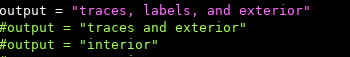
For exporting the labeled PCB.
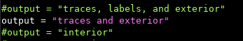
For exporting the traces.
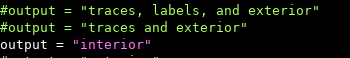
For exporting outline, and I exported all of these with a resolution of 25 pixles.
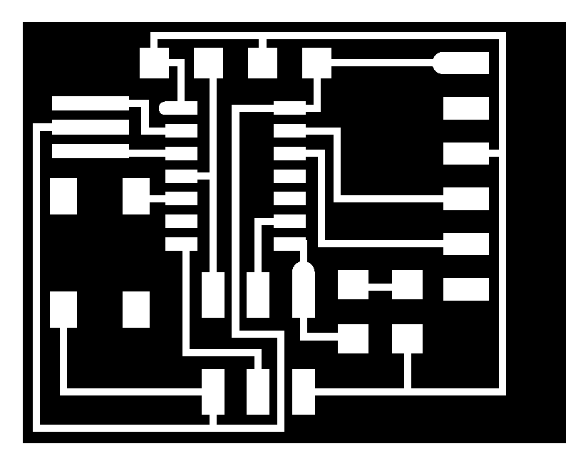

And now it was the time to import the png images to fabmodules, to generate the toolpaths for the traces and the outline:
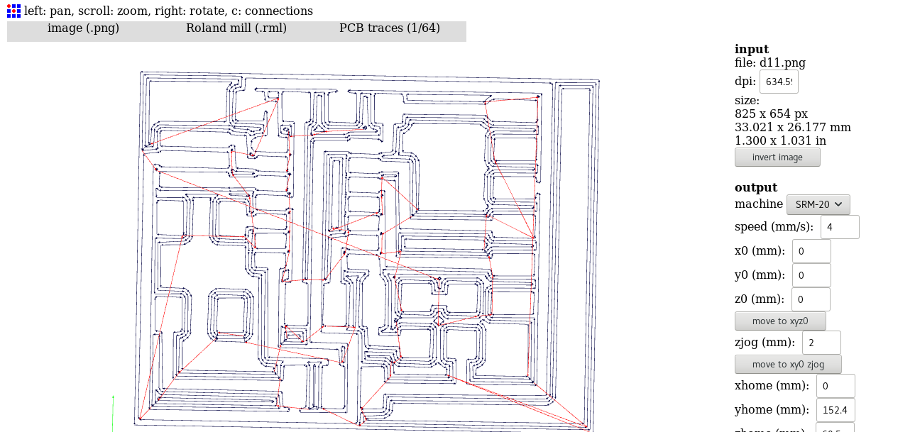
And after that it was time for milling the PCB, and I used the Roland SRM-20 that we have in lab, for milling the traces I used the 1/64 inch milling bit and for the outline I used the 1/32 inch milling bit:
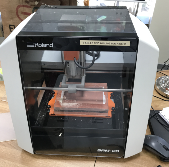
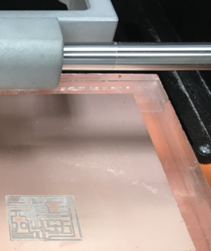
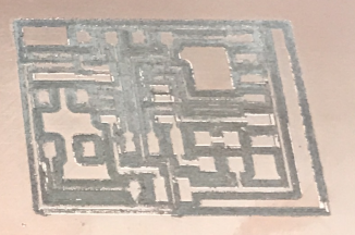
Then I milled the board (I used a broken bit for the traces because all of the bits in the lab were broken and I could not wait till the new bits arrive) spoiler alert!! it worked fine:
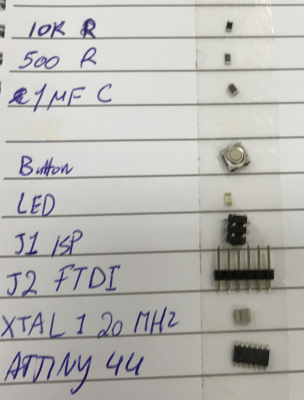
Then I started collecting all the components needed for stuffing the board and I arranged them so that I dont get confused later:
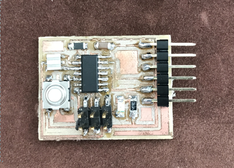
Then it was finally time to stuff the board, so I stuffed the board and when I finished it looked a bit ugly (broken bit) but thats ok as long as it works:
Previous Week |-----------| Next Week