
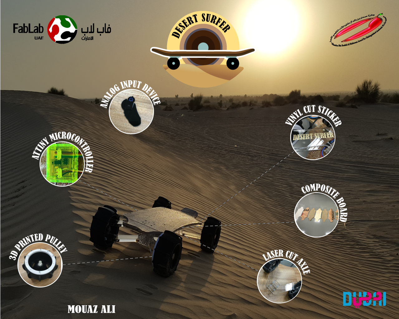
For my final project i was advised to think of something related to the local environment here in the UAE, and as i live in Dubai which is in the middle of the desert, i was thinking of making something related to the desert. So my project is a skateboard that you can skate with it in the desert above the sand jumping from one sand dune to another.
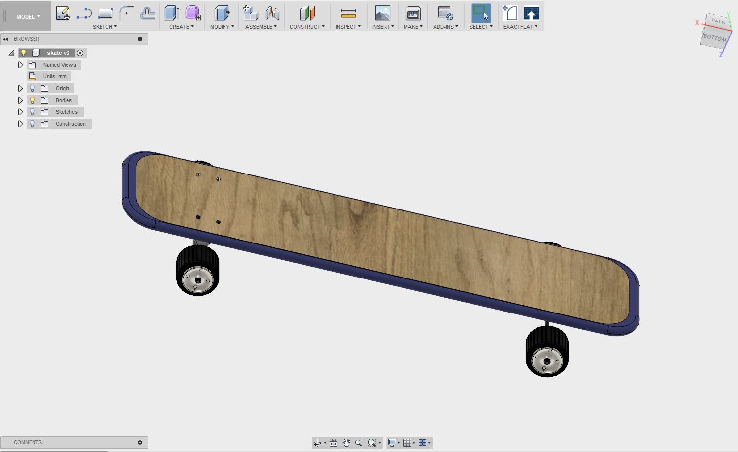
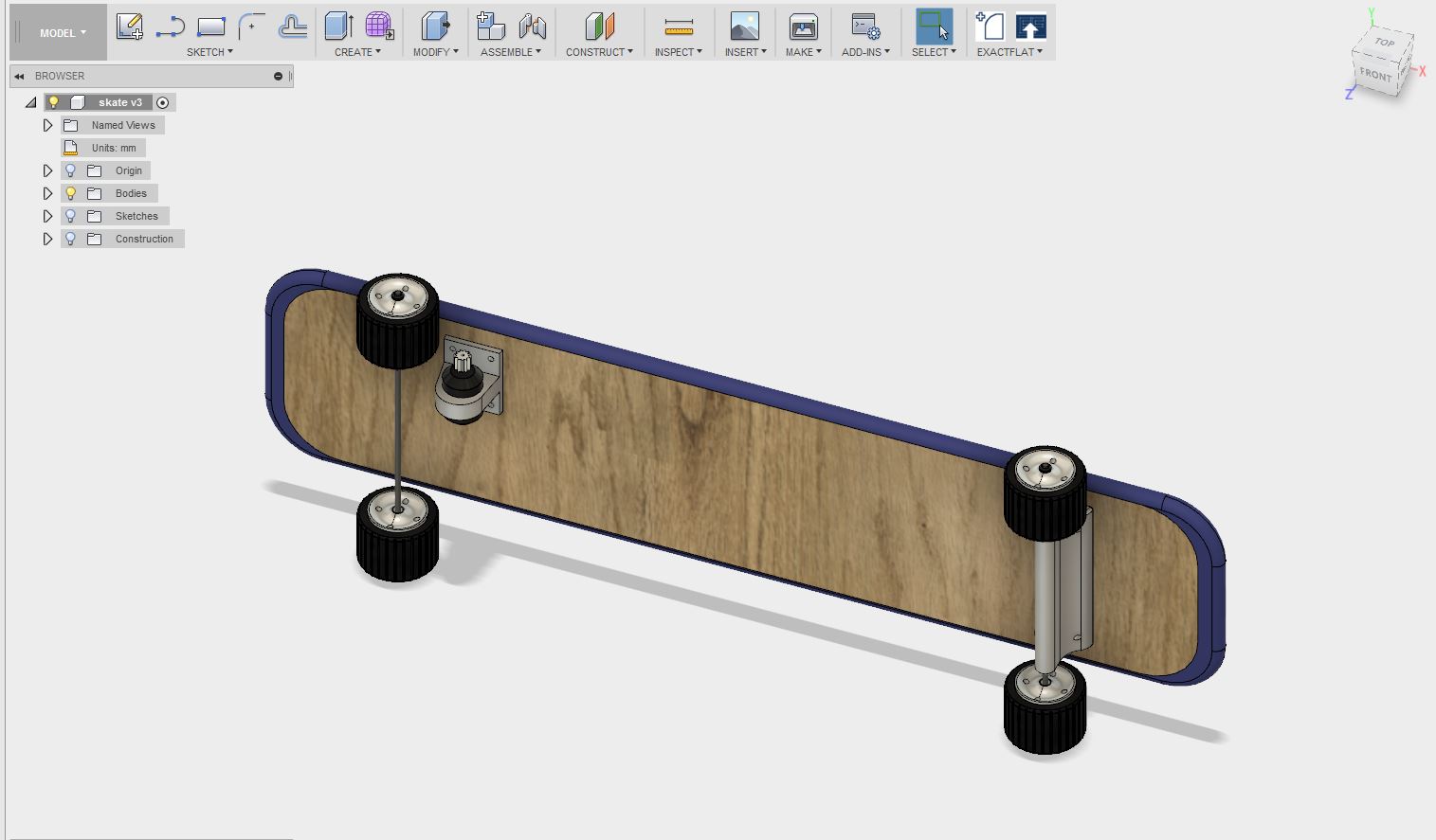
Here is the first sketch of my project and a 3D model:
The first thing I did was looking through the archive to see if someone did this project before, and I found a guy named Kosuke Kaneko from 2016 class who did an electric skateboard, it looks good but I did not like the final look I thought it's a bit big and the box below the skate could have been done better. the other thing I noticed that my skateboard will have more fabricated parts than his.
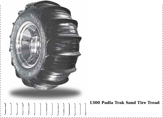
Before starting any thing I knew that one of the major problems that am going to face during this project is the wheels, as we all know that not any type of wheels works or can be used in the desert because they might sink in the sand and get stuck.
so I started searching for the types of wheels or tires used for desert bikes or buggies, I found a lot of patterns for the wheels and some really useful websites like sandtiresunlimited. I finally decided to go with this type of tires because I thought that this kind of pattern might really work:
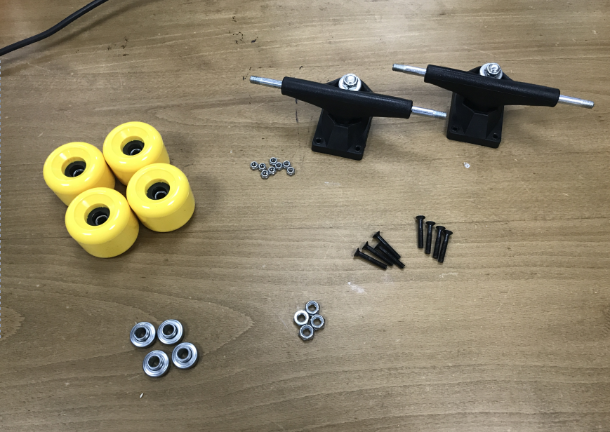
Then I went and bought a skateboard and disassembled it so that I can use some of the parts in my project:
I started by designing a wheel that will go around the skate wheels that I bought so they will act as a rims for the new wheels and I wanted to print them using flexible 3D printing filament, when I started printing the wheels I faced a problem, the issue was that the print keep sticking out of the plate even after I have tried so many times to change the plate temperature.
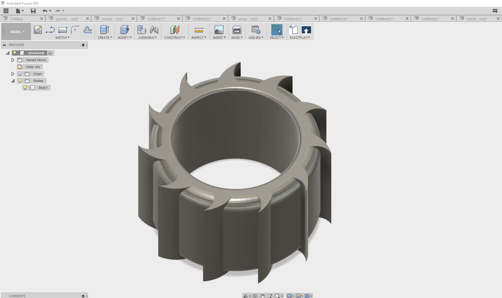

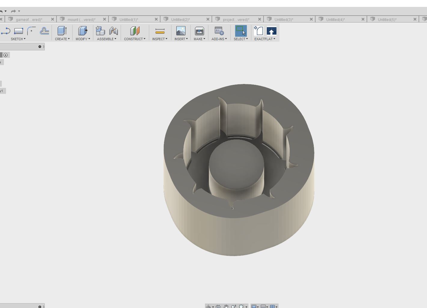
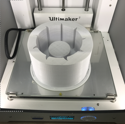
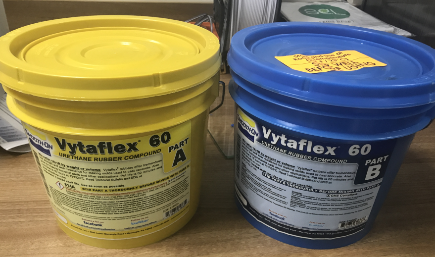
Then Neil advised me to try making a mold and to cast the wheel using urethane rubber, so I bought the rubber from a local supplier and designed a 3D mold and Printed it using our 3D printer - Ultimaker2 - the final print was not that good but I didnt think that it will cause a any problem, SPOILER ALERT!! it did.
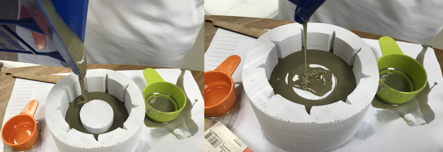
Then I started preparing everything to make the rubber wheel and cast it into the mold, so after measuring the volume I started mixing the part A with part B with a mixing ratio of 1A:1B by weight or volume as labeled on the product.

After I finished mixing it was time to cast the rubber into the mold and that what I did, and then I left the rubber to cure over night.
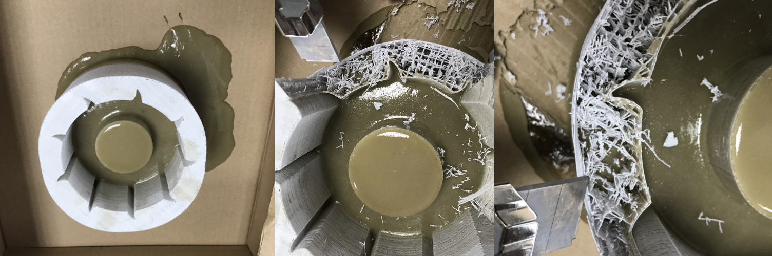
The next day I was ready to take my wheel and try it, but then I found out that things didnt work as I planned, when I was trying to take the wheel out of the mold I found out that the rubber had formed a sort of composite with the 3D printed mold, the rubber had gone into the small gaps within the mold (it was a bad print), so that didnt work also.
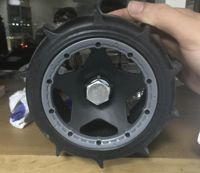
After that to save time I went and bought wheels that are made for RC cars to try them out.
I did the board in the composite week assignment, here.
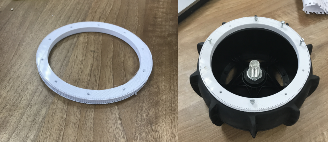
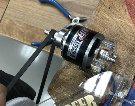
As am using these huge wheels for my skateboard, I had to make a special pulley, so I decided to 3D design a pulley that is going to fit my wheels. I had a small pulley which is going to be attached to the motor and I also had the belt which goes along with it, so the only thing remaining was to design the big wheels pulley. Any pulley goes under a class like HTD,MXL or XL, then I came across this guy who did this amazing parametric pulley design in thingiverse, so I downloaded the design and I had to change a lot of things in it. My pulley class was MXL, so I had to change the diameter of the pulley the inner and the outer, add some holes for the screws and add two edges to the sides so the belt dont get out of the pulley, but this was not the problem, the problem was that this whole thing was designed using openscad, which I have never used before. so I had to watch some tutorials online and at the end I was able to finish modifing the pulley, and printing it.
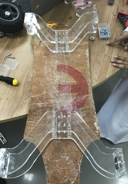
In order to hold the wheels, which are not made for skateboards and to connect them to the board and for the skateboard to be able to withstand my weight (85kg), I had to design a special axle or connector, and for that I designed it using 12mm acrylic hoping that it will be able to carry me. For designing the axle the software I used was CorelDraw, I started by designing these small connectors that will hold a bearing and will be attached to the wheel.

After that I had to design the long axle that will be the bridge between the small connectors attached to the wheels and the board.While designing them I added two small support pieces the size of the small connectors.
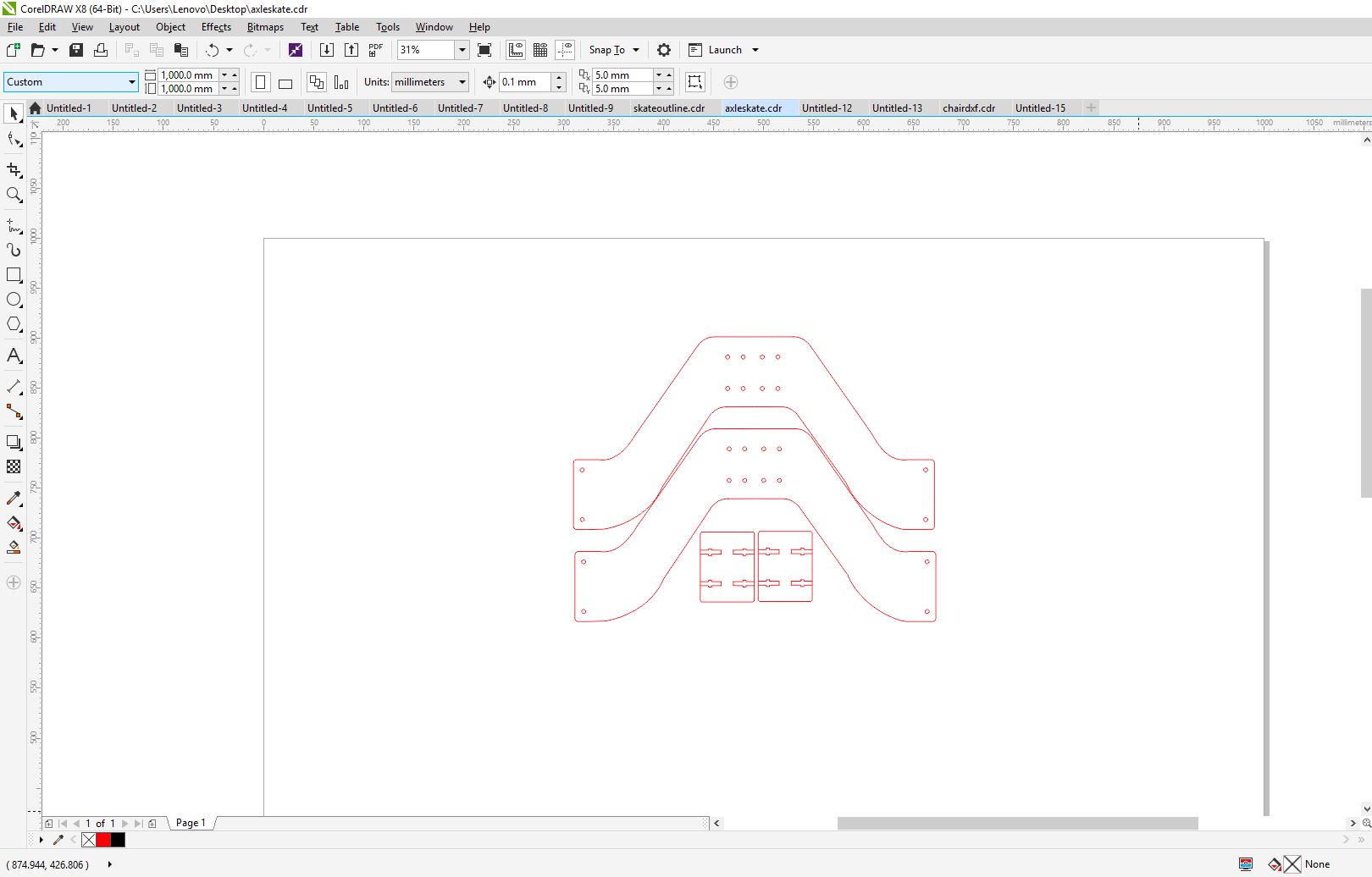
After that I cutted the whole thing using the laser cutter, and attached it to the wheels.

For the electronics parts that I bought for this project they are listed below with the source.
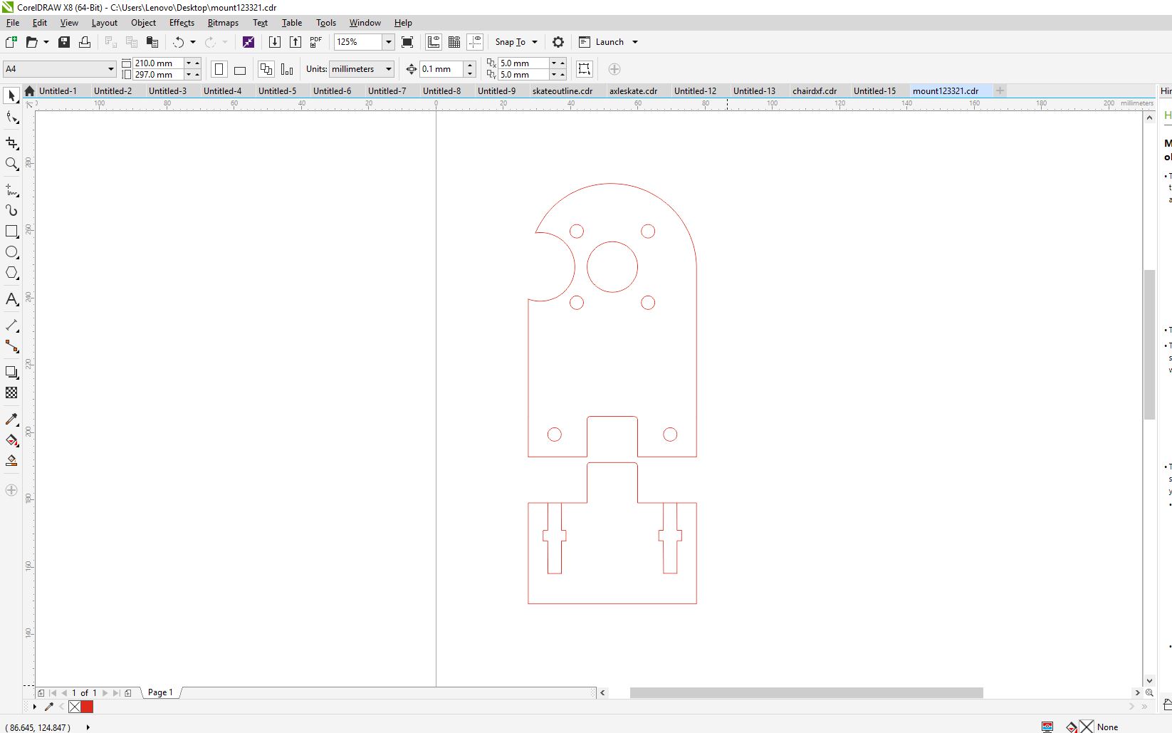
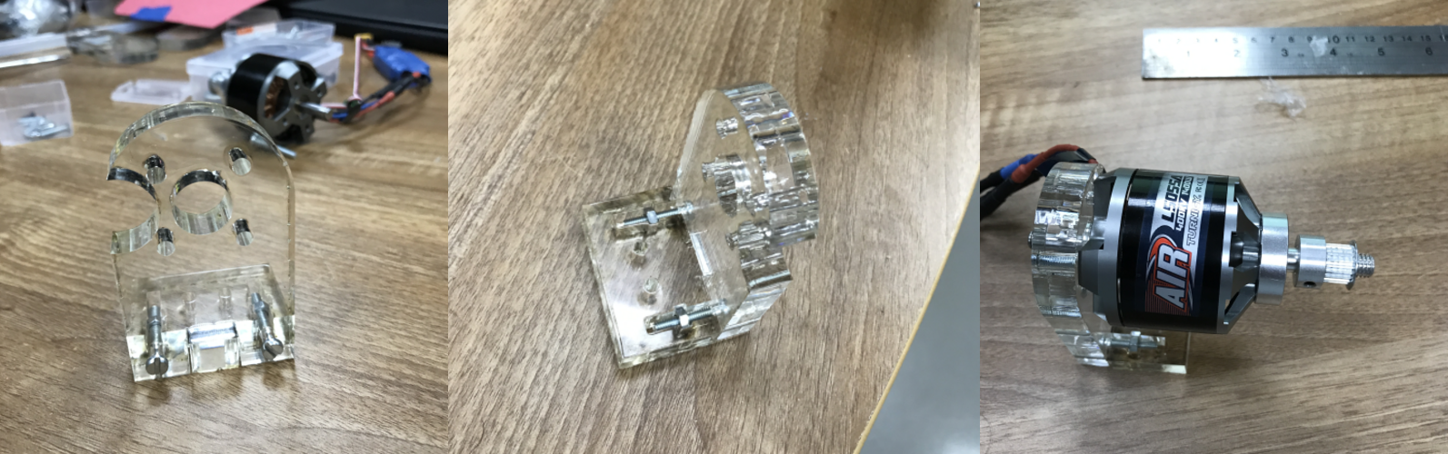
In order to hold the motor to the board I had to design something that will hold the motor in place while riding the skateboard, so again I used the 12mm acrylic and using CorelDraw I designed this really cool motor mount.
For this project I have designed two boards one for the skateboard to control the motor with the ESC and the other one will be attched to a potentiometer in the controller later on, as always I used kokopelli to design my boards.
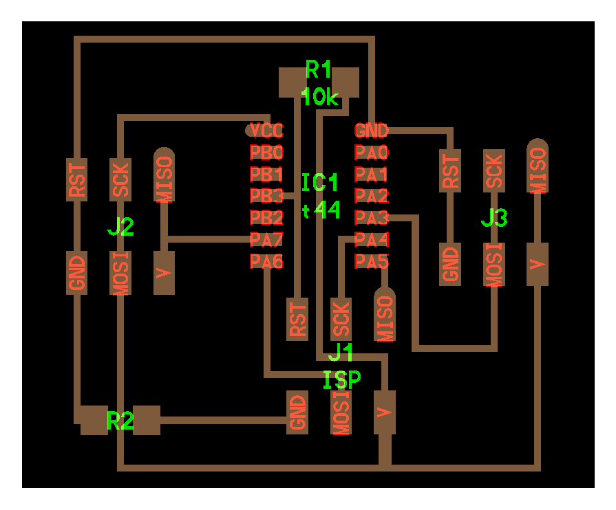

When I was done with the design it was time to mill the boards and to stuff them.

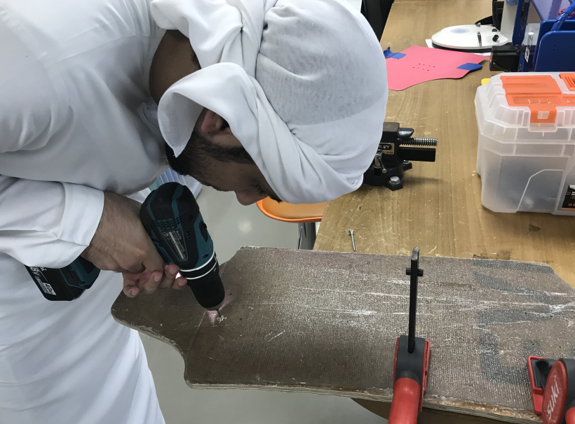
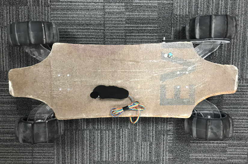
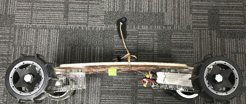
Now it was time to put everything togather and to assemble the skateboard. so I started first by mounting the board to the axle and I did that by cutting some card board with the exact size of the skate in order to drill the screws in the exact place.

After that I fixed the motor to the board with mount that I designed earlier, and the skateboard was almost ready.

Here is a video while testing the motor after mounting it to the board.
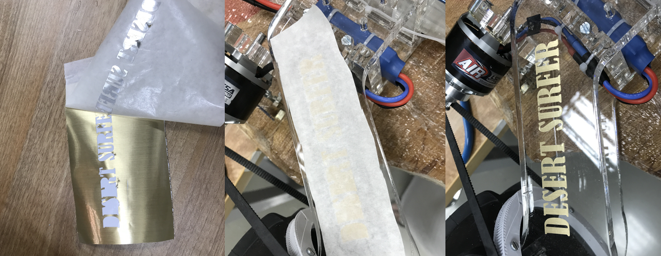
So I used the vinyl cutter to cut this logo that I designed with the name of my project "Desert Surfer".
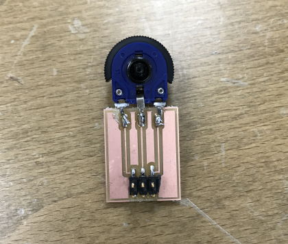
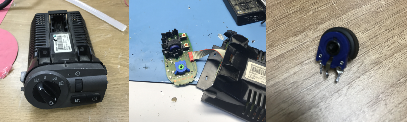
For making the controller that am going to use to control the speed and the whole skateboard, so the first thing was to find a good potentiometer to use and then I found this old car's AC controller and desoldered the potentiometer out of it.
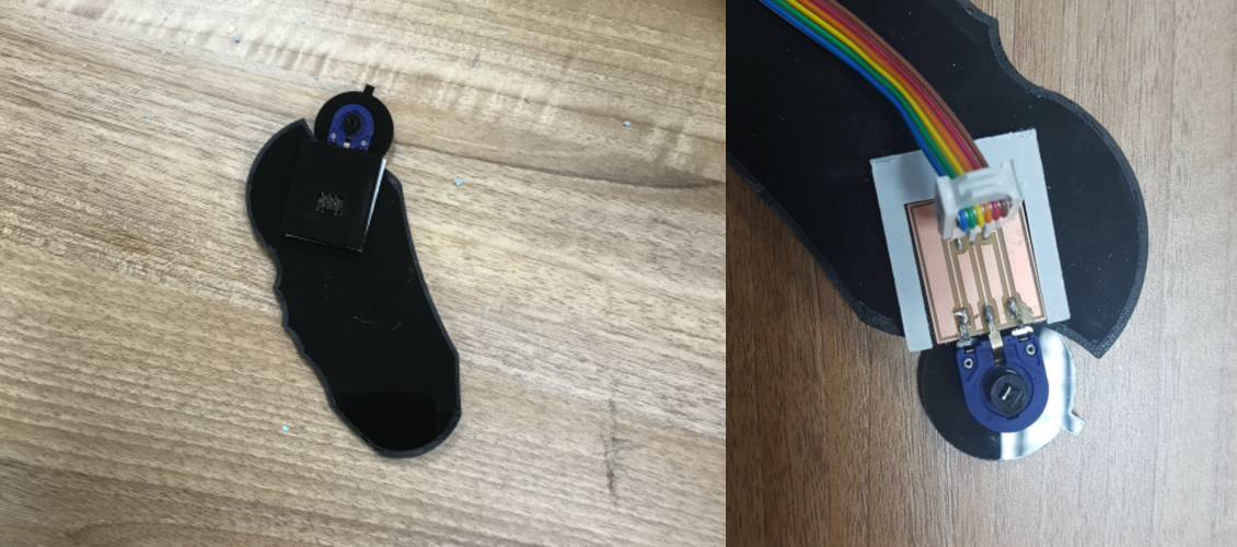
After I made this laser cut cover that will cover the potentiometer with the PCB I made earlier.
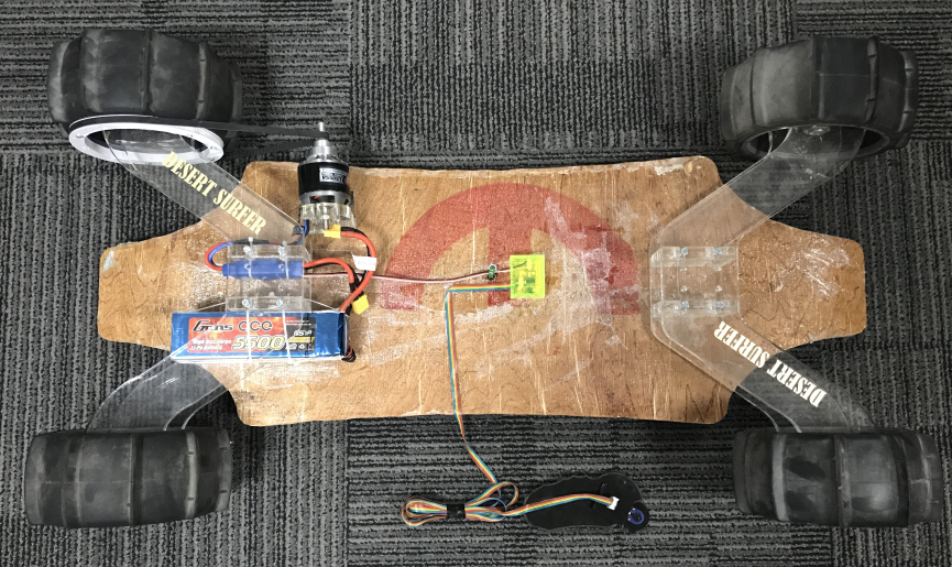
So the next step was to mount the boards and all of the the electronic components to get the final thing ready. For the battery and the ESC I attached them to the axle using zip ties. For the board I created a press fit box to protect the board form the surrounding environment, and I created holes in it for the wires to pass and then used a strong double tape to mount the board to the skateboard, because I didnt want it to be fixed forever, to be able to change anything later in the future if I want. regarding the wires I used a gluegun to fix them into the board so that they dont move while the skate is moving or dont get trapped in the wheel espcially the controller's wire.
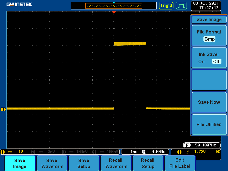
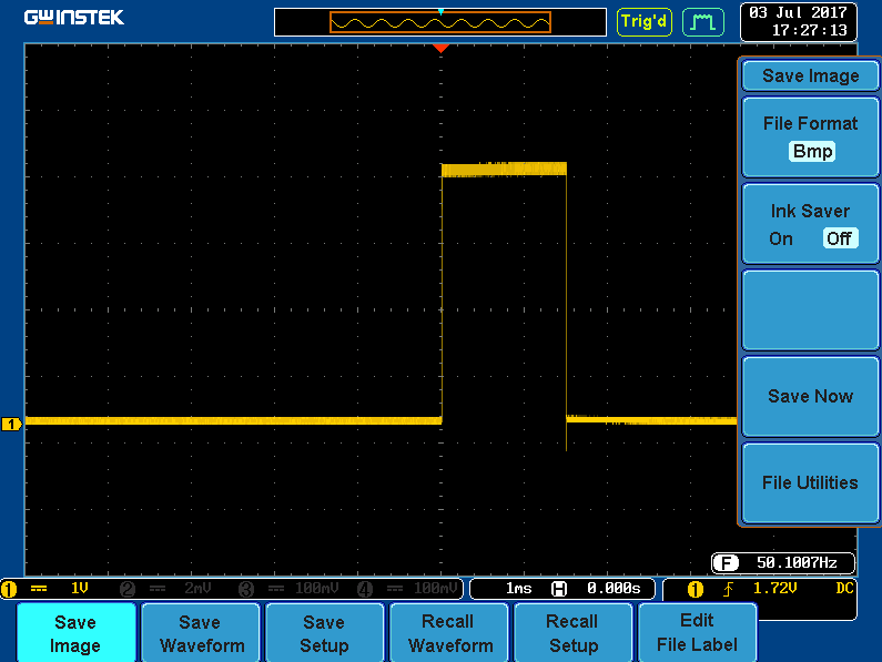
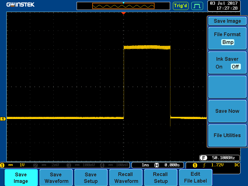
So in order to programme the project I have to use ADC (Analog to Digital Converter), which I have already used during week13, as well as generating a PWM (Pulse Width Modulation), so the first I did was looking at the ESC datasheet or manual to get all the specs needed to run it. As am using an ESC in the project, and ESCs are PWM controllers for electric motors. The purpose of the ESC is to vary the motor's speed, its direction and also to act as a brake. The ESC generally takes a 50 Hz PWM servo input signal whose pulse width varies from 1ms to 2ms. When supplied with a 1 ms width pulse at 50Hz, the ESC responds by turning off the DC motor attached to its output. A 1.5ms pulse-width input signal results in a 50% duty cycle output signal that drives the motor at half-speed. When presented with 2.0ms input signal, the motor runs at full speed due to the 100% duty cycle output. So what I did was taking Neil's servo motor code and modifing the code by using ADC to obtain the value from ADC register and then map it to the PWM values in the code, so I have to map 0 and 1023 to 1250 and 2500.
So I used this mathmatical operation to map the values, so if the number X falls between 0 and 1023, and you would like Y to fall between 1250 and 2500, we can apply the following linear operation: Y = (X-0)/(1023-0) * (2500-1250) + 2500. getting abck to the Attiny44 data sheet, I found that The double buffered Output Compare Re gisters (OCR0A and OCR0B) is compared with the Timer/Counter value at all times. The result of the compare can be used by the Waveform Generator to generate a PWM.
so in order to map the values I used this OCR1A = (ADC-0)/(1023-0) * (2500-1250) + 2500. ;
Then I used the oscilloscope to see the different frequencies generated.
the video below shows the skateboard working perfectly.
I did a BOM during week17.
link to my slide.
link to my video.
My project licence that I chose is documented in week18.