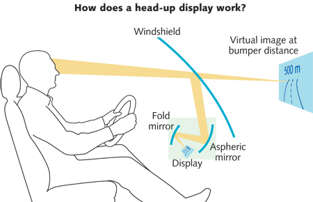
Basic concept
For my project I have decided to do a navigational assist for helmet. My inspiration is from Google's Glass project which is a fine tool but it still cost a forturne. My intension is to integrate the same principle into the helmet without digging a pit in my pocket.
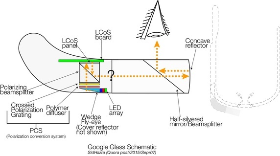
Optical path in google glass
Proposed system hand drawings
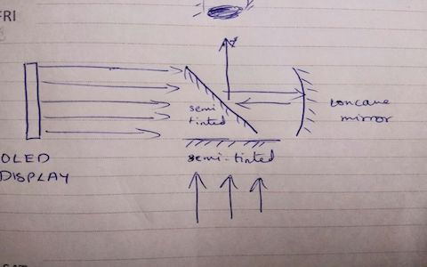
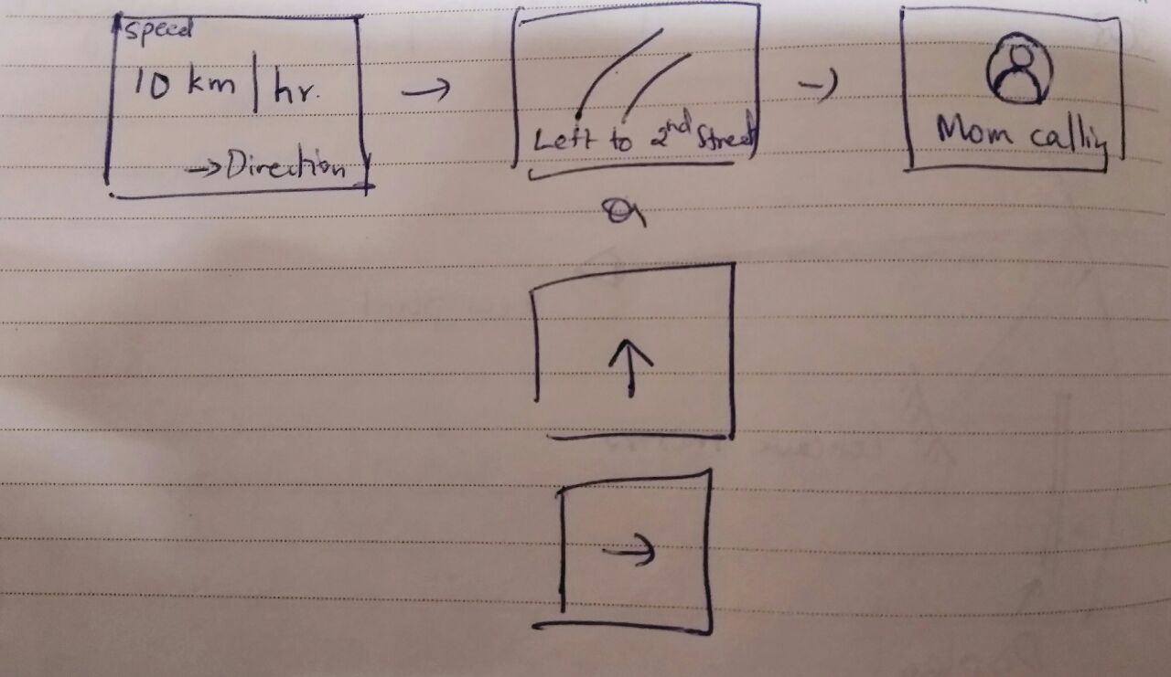
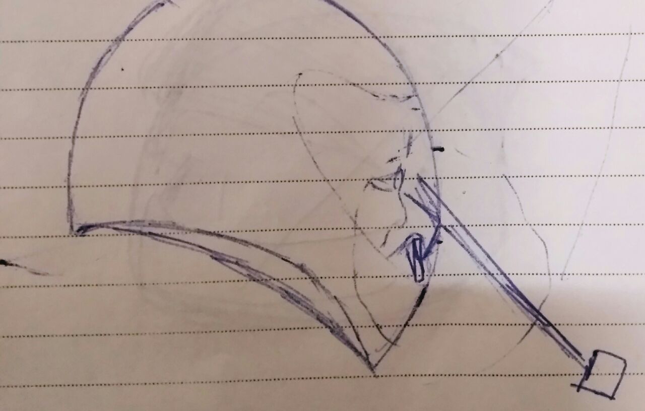
The display module in the proposed system is an OLED screen, which has high contrast and low power consumption. There are OLED screens far smaller than 1 inch. If I can get hold of it, I will probably use that for integration. I intend to use a Bluetooth module to send display data and a rotary encoder to toggle between the display screens.
Project Presentations
Before I start into my complete documentation, go on and checkout my presentation slide and video. The video is an aggregate of all the process I went through with this project, some process ended being just research works and did not make into the final device.
Your browser does not support the video tag.
-->
I have ran through a lot of iterations to finally end up with the final device. I did step by step process to make sure I could actually complete the project. So I'll try to document my project based on these steps.
Research and Development
There were a couple of documentations available in Instructables to build a similar google glass using arduino. I went through those works to identify the constraints I would have to carry out in my design. The problem I found from these designs is that it could reduce the peripheral vision when you are riding a motorcyle. I did not want to compromise vision when riding.
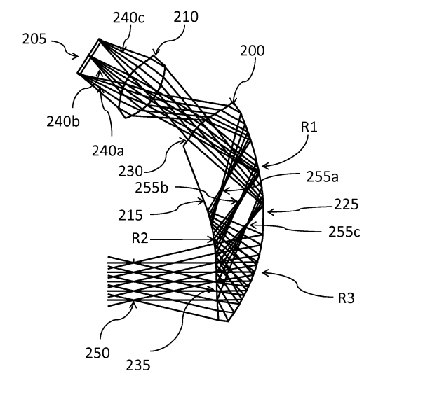
I read through a lot of research papers to figure out the optics involved in HUD designs. I short listed couple of technologies that were used in some of the papers, one is a waveguide holographic display using acrylic and another is a research paper on freeform prism. I decided to try out each of them.
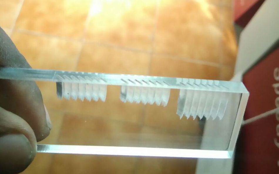
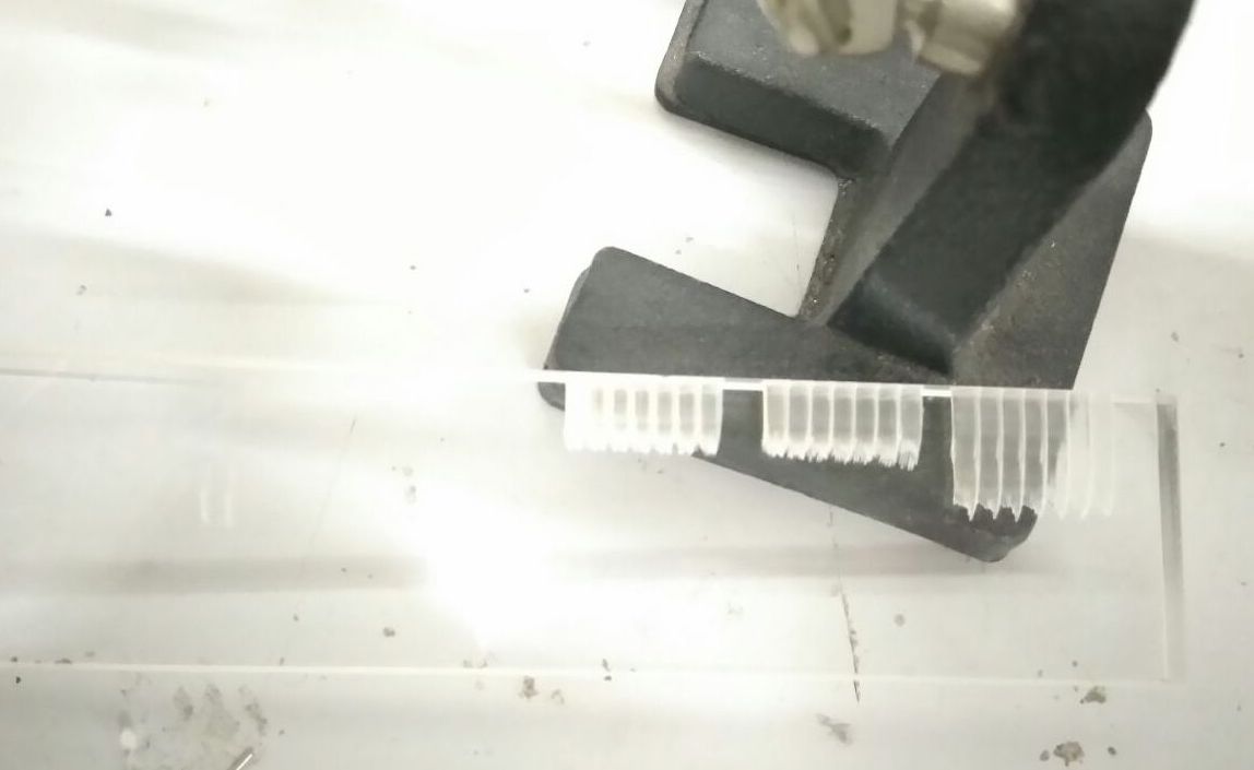
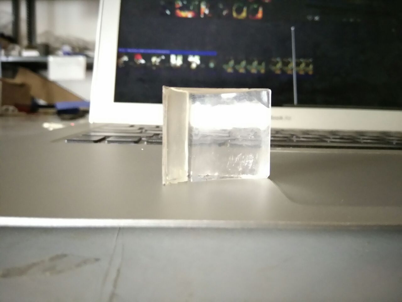
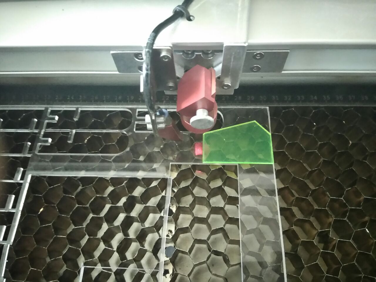
I started out with waveguide holographic design. I was very sceptical if its even possible to cut a reflective surface using our CO2 laser cut.
I was able to but vertically through the edges of a 6mm acrylic. I placed the acrylic on the edges and placed support structures during cutting angles on it. Eventhough I was able to cut as shown in the following images, I assumed I would need more processing involved to make those cuts reflective and more calculations on the distance between cuts. I decided not to proceed with this technology.
I then went through the second research paper, which was promising because the researchers did casting plastic to make their design. But they did not give a complete documentation of the dimensions of the design. I approximated my design based on the diagrams provided in their research. My final casted freeform prism is also shown.
Following is the process of moulding and casting the freeform prism.
I started of with laser cutting the design and used cholorophorm to stick everything together.
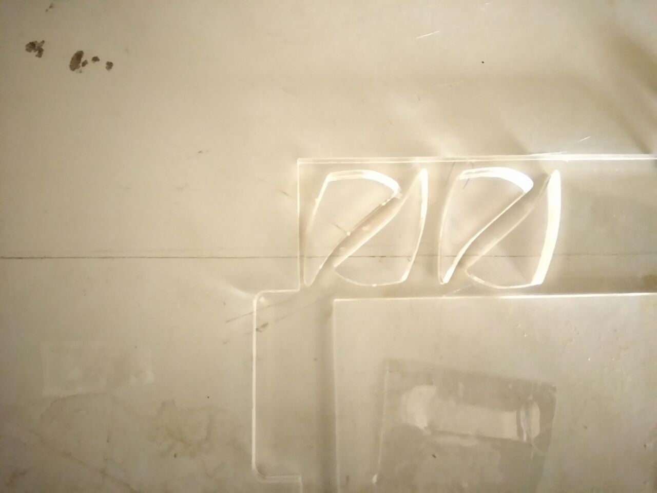
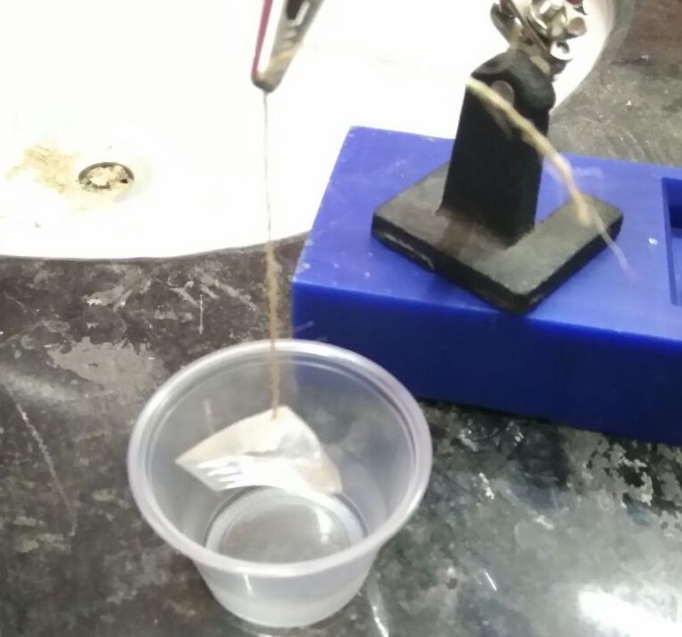
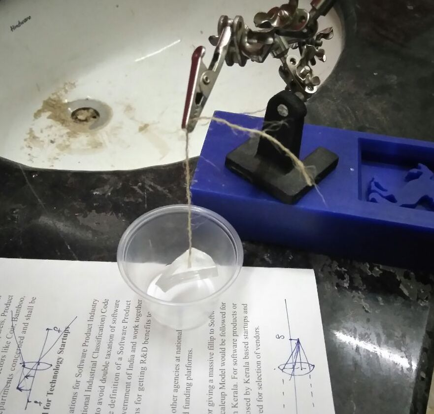
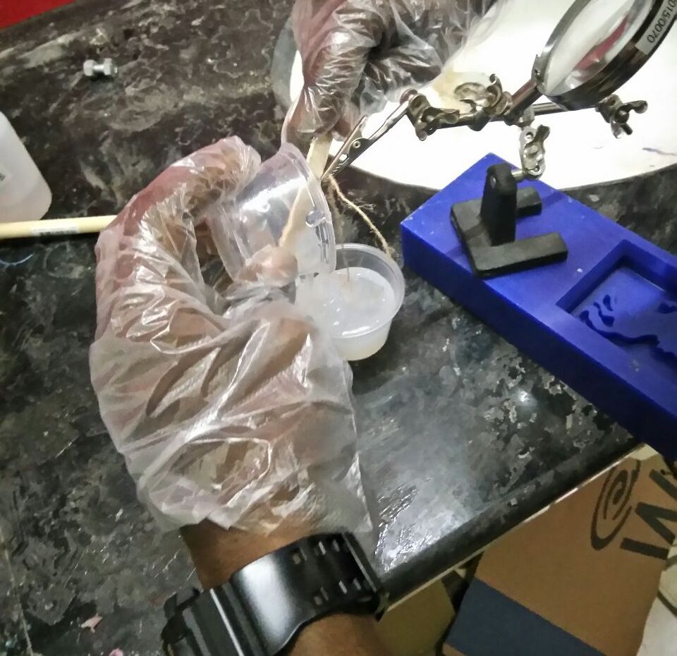
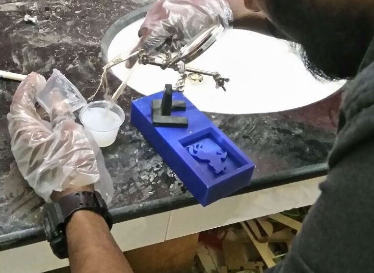
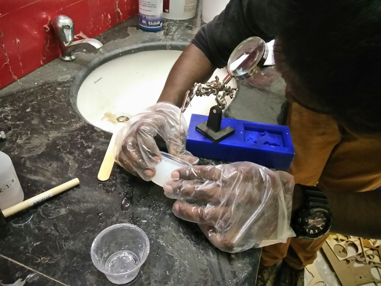
I filed all the edges to make sure they have smooth edges and used that as the negative to create the mould. Following images shows me working to create the mould.
I hung the acrylic freeform prism negative onto a container and filed it with silicone rubber to create the mould. I used LSR 1- A and LSR 1 - B in the ration of 10 : 1.
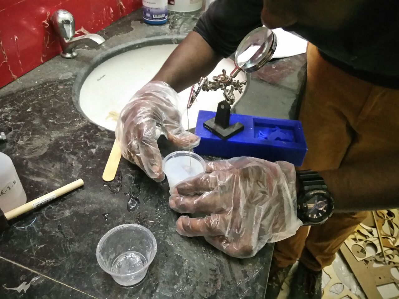
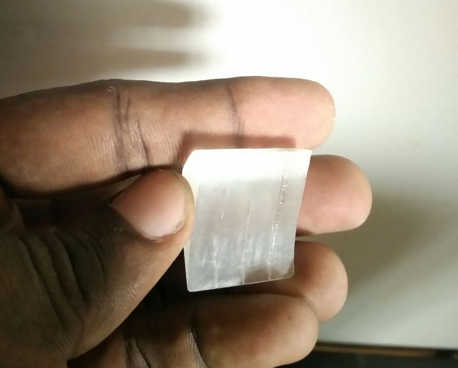
After curing the mould,
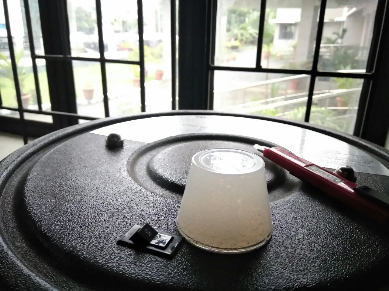
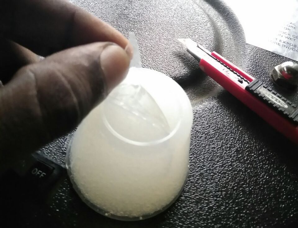
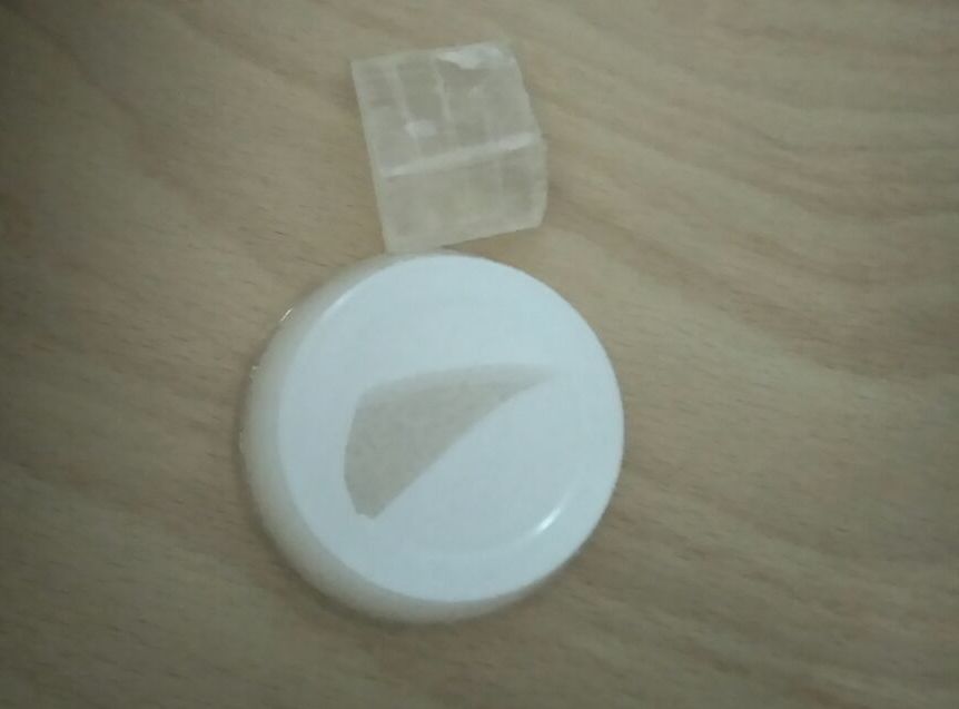
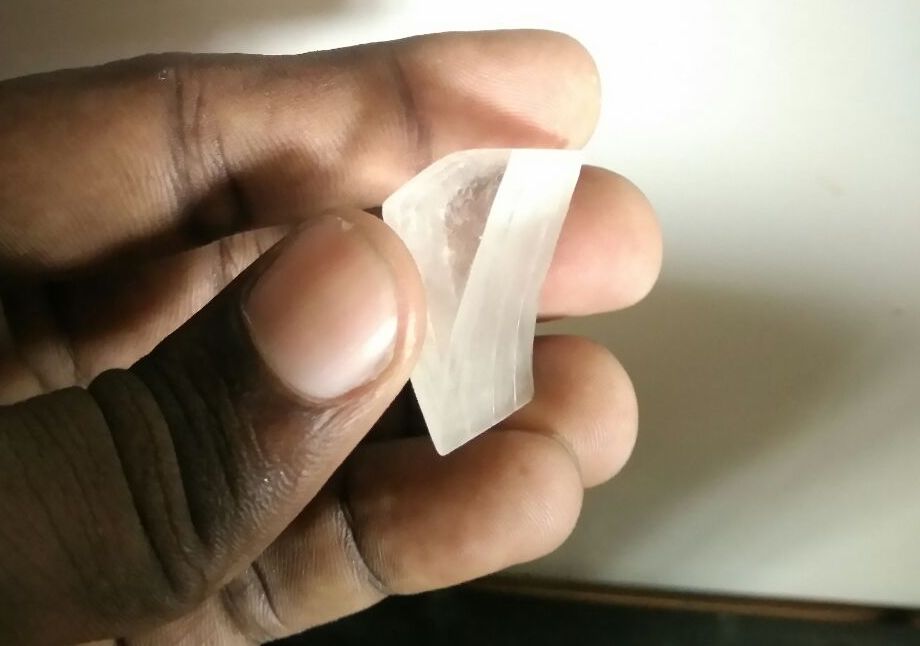
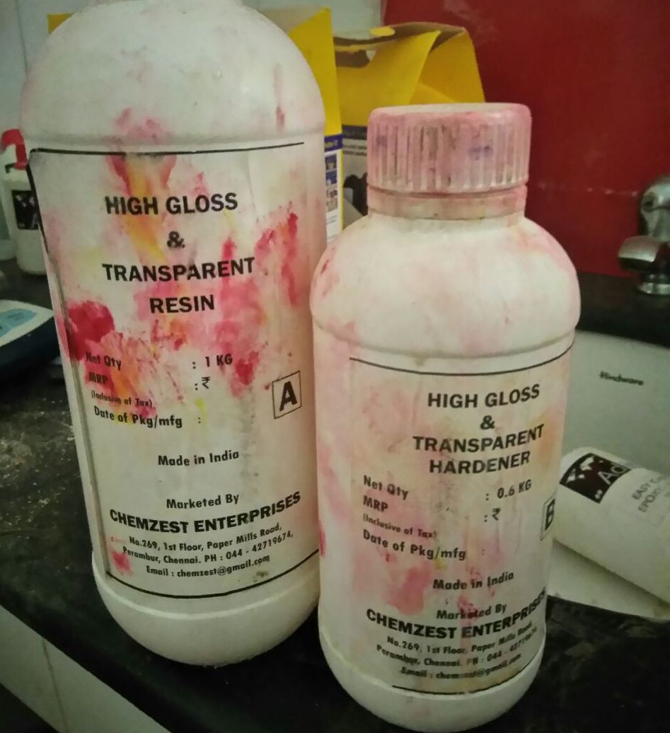
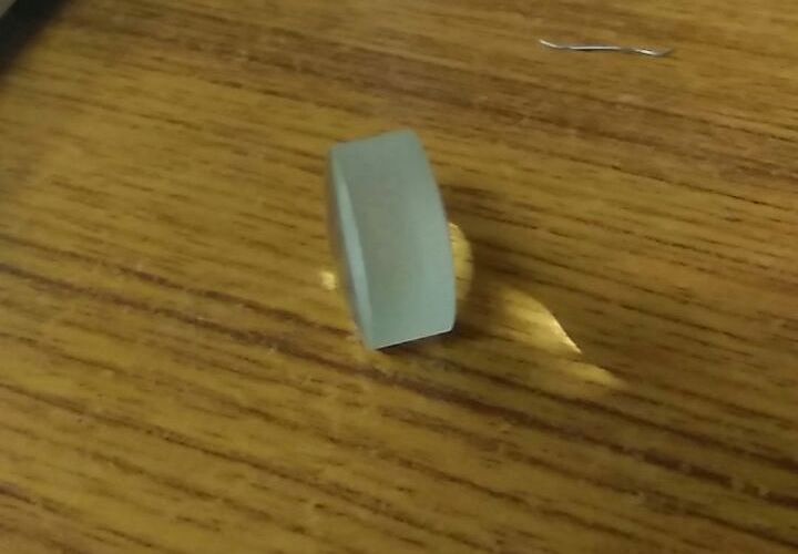
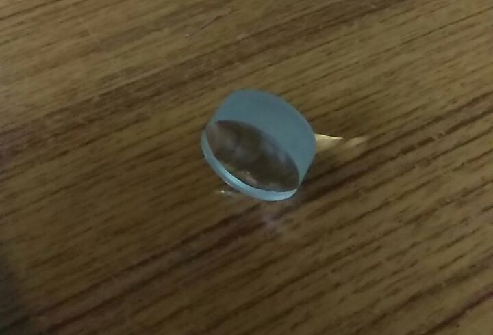
I poured plastic mix which has a ratio of 10(resin):6(hardner) on to the mould and set it for curing. The output,
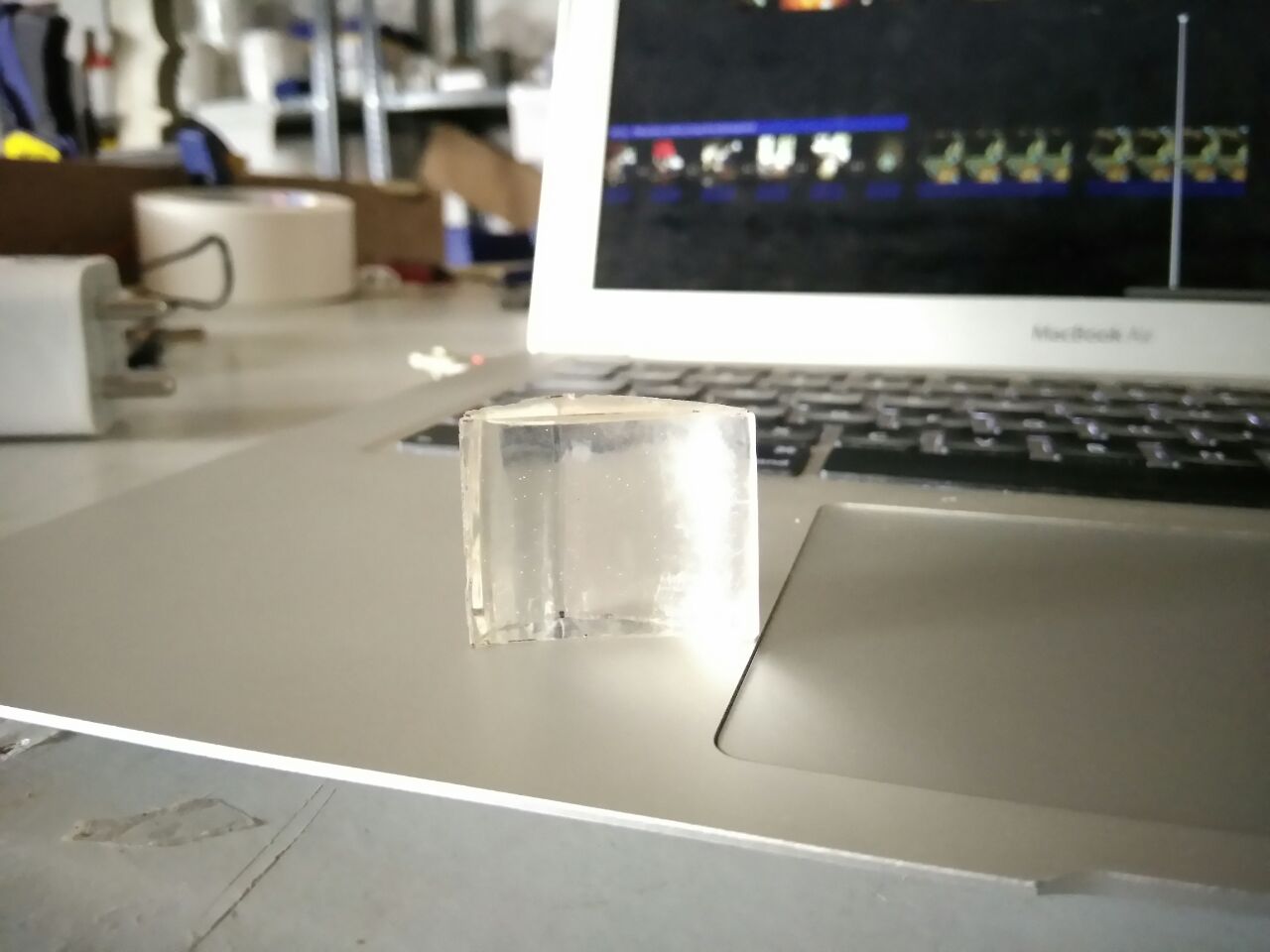
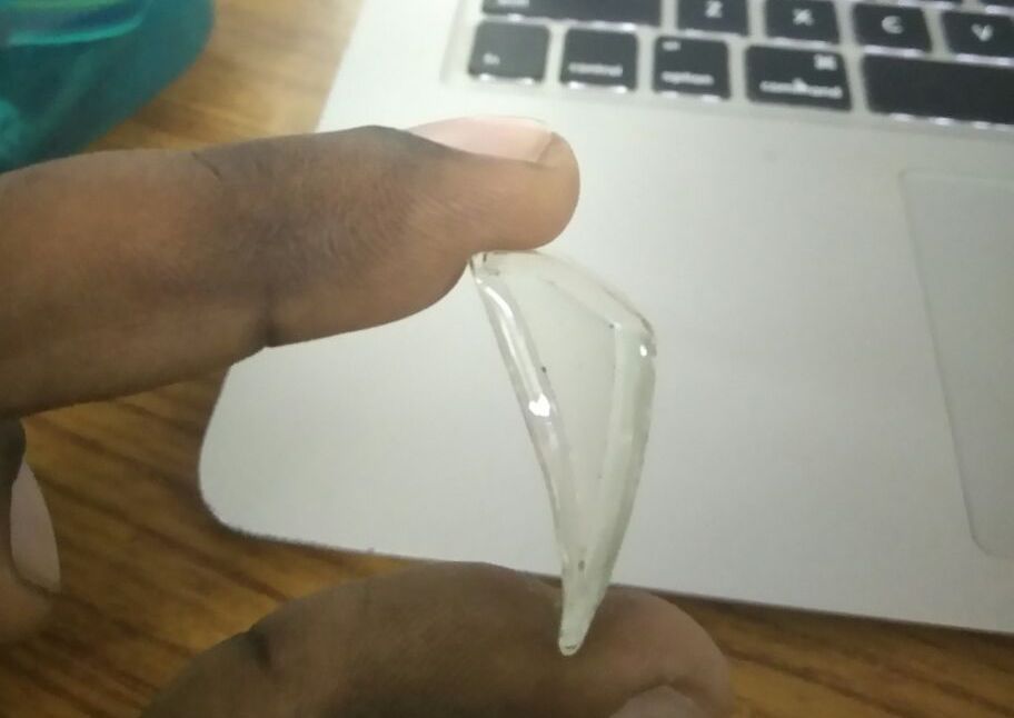
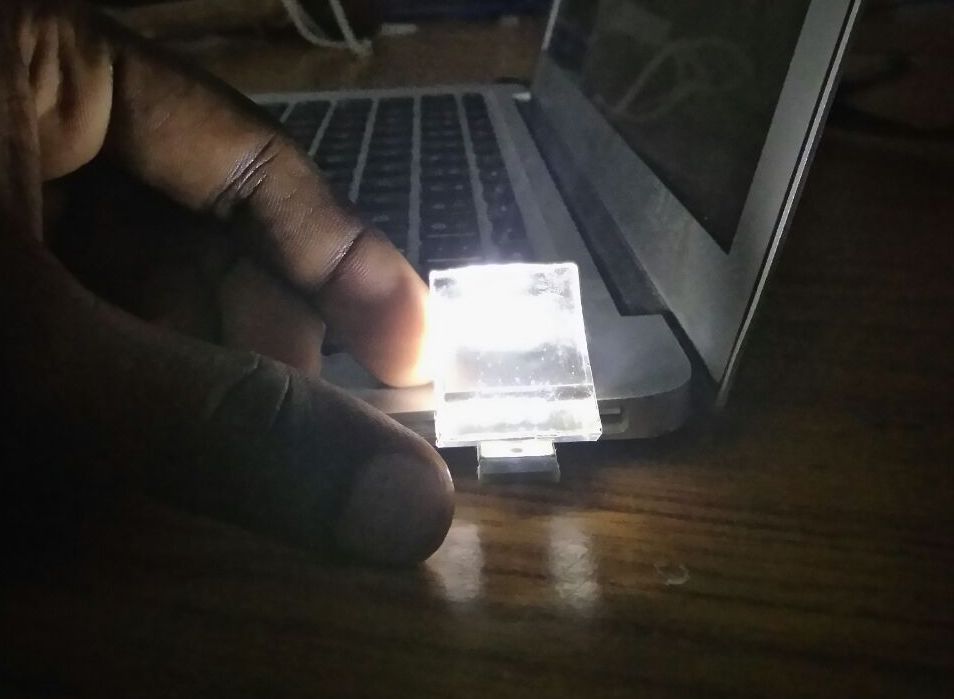
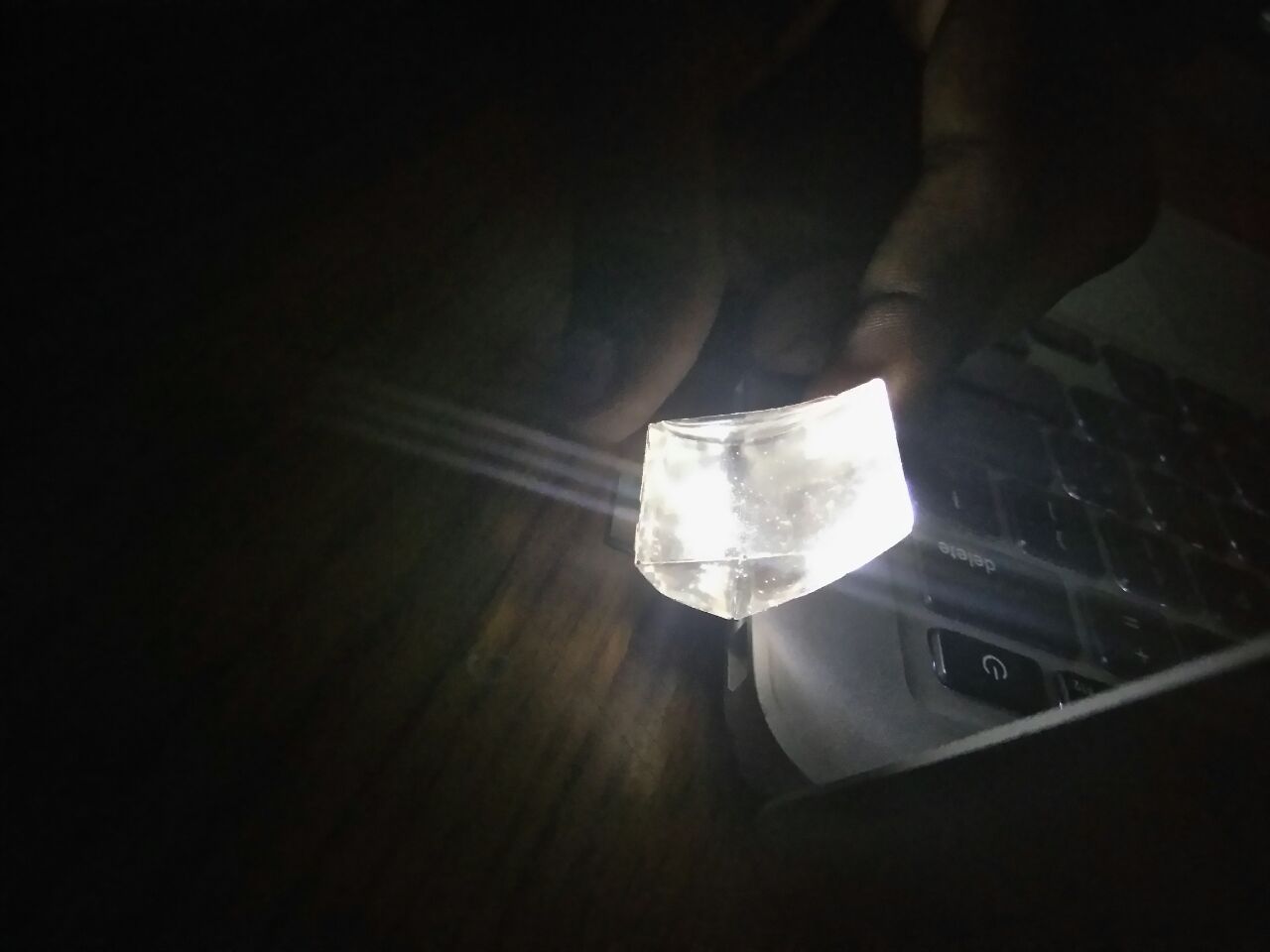
Testing out the freeform prism; the light source is at the flat edge of the prism. You can see the second image depicts the exact working of the prism. The light passess through either side of the prism. This proves that the design actually works.
But I could not move ahead with the freeform prism because there was lot of distortions happening within the prism. This is probably because of the bubbles formed during the mixing of the resins and also with the edges of the mould which was made from acrylic. There was also a image shift happening when looking through this prism. For these reasons I did not move forward with this casted prism.
Figuring the feasiblity of the project.
In my Interface and Application Programming week, I was able to get my OLED display working and control it via bluetooth by sending control signals. So now I had to figure out the optics so that I can get the OLED projected on to the wearer's eye.
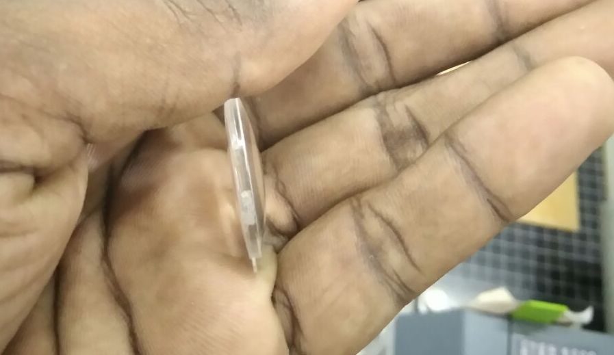
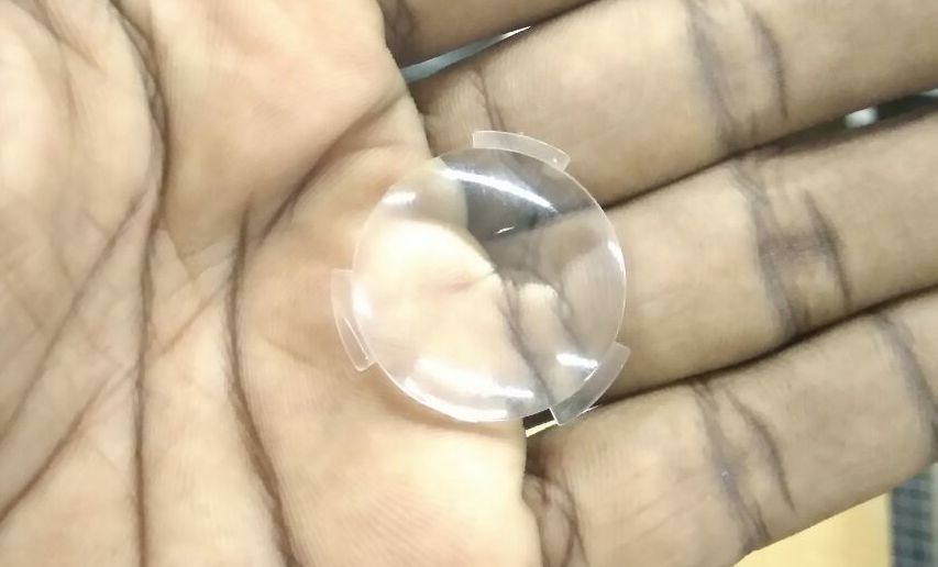
I got a triplet jewellers magnifier which has 30x zoom.
I found the magnifier we have at the Fablab useful for my project.
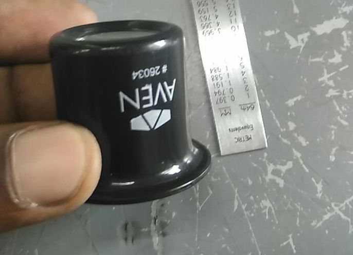
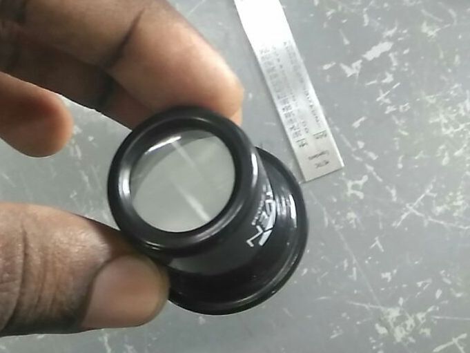
The focal length for the triplet lens is at 3cm. I was able to get more magnification when combining with lens from the second magnifier. This also reduced the optical distance of the system. So I decided to use the lens from both the magnifier for my project.
First Iteration
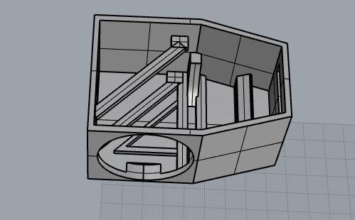
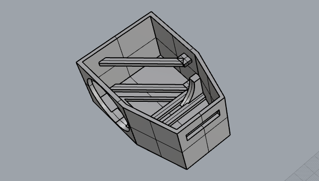
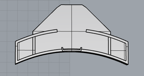
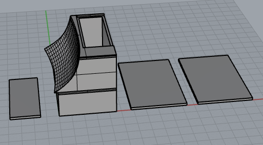
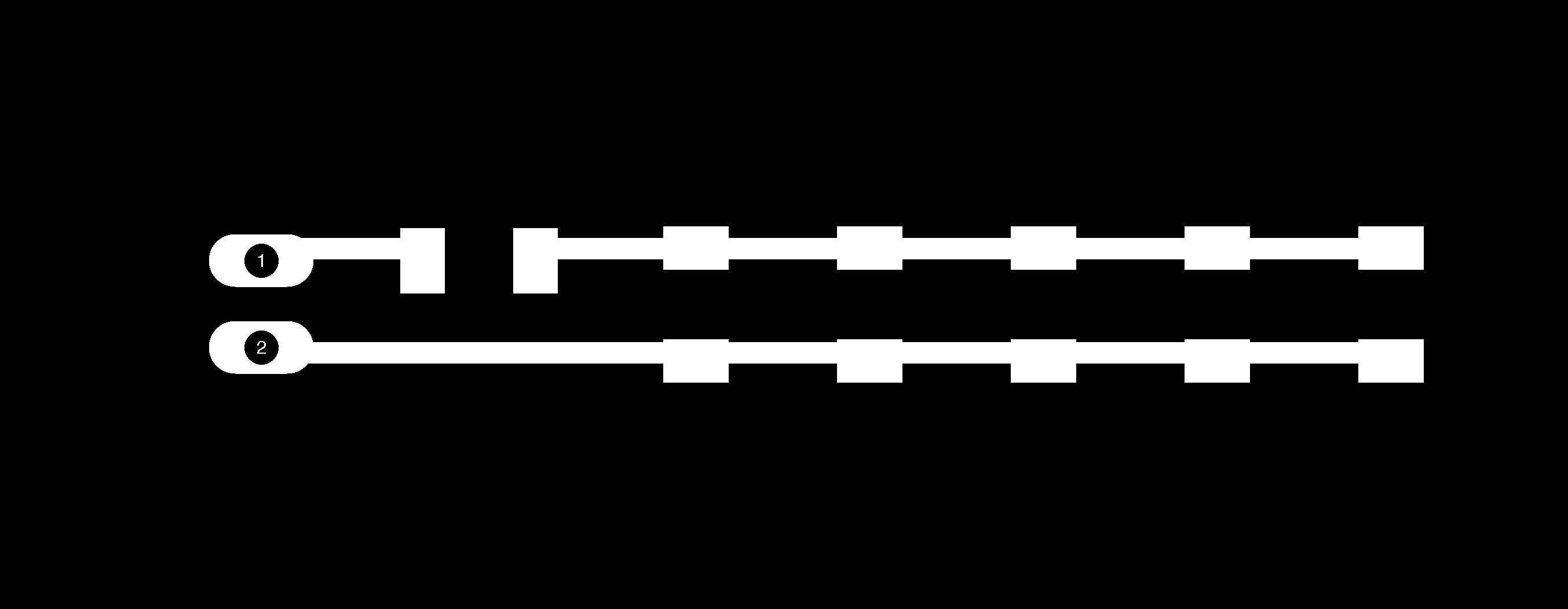
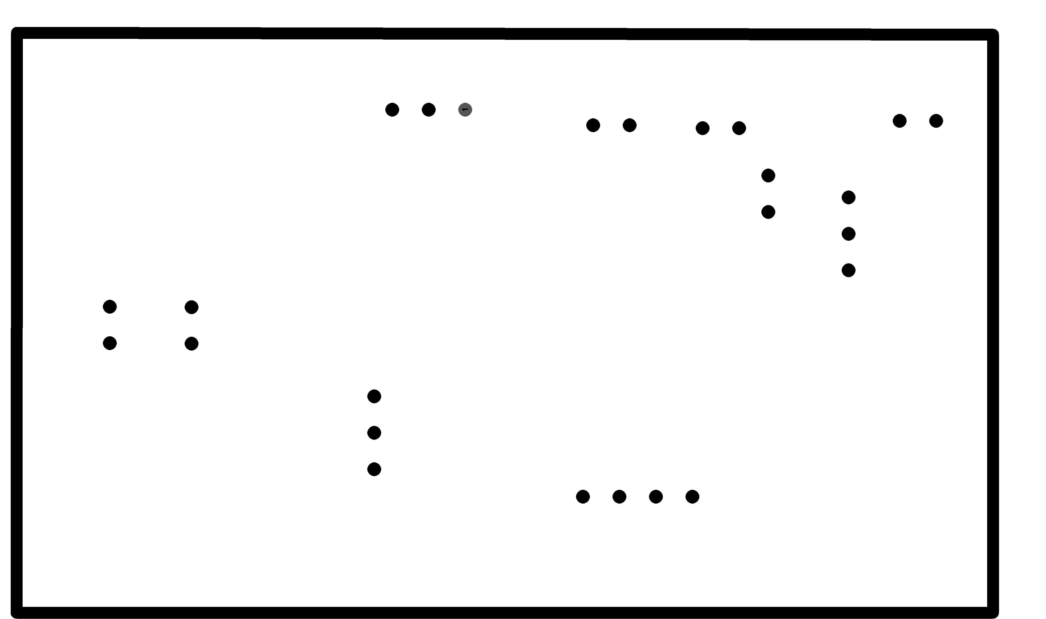
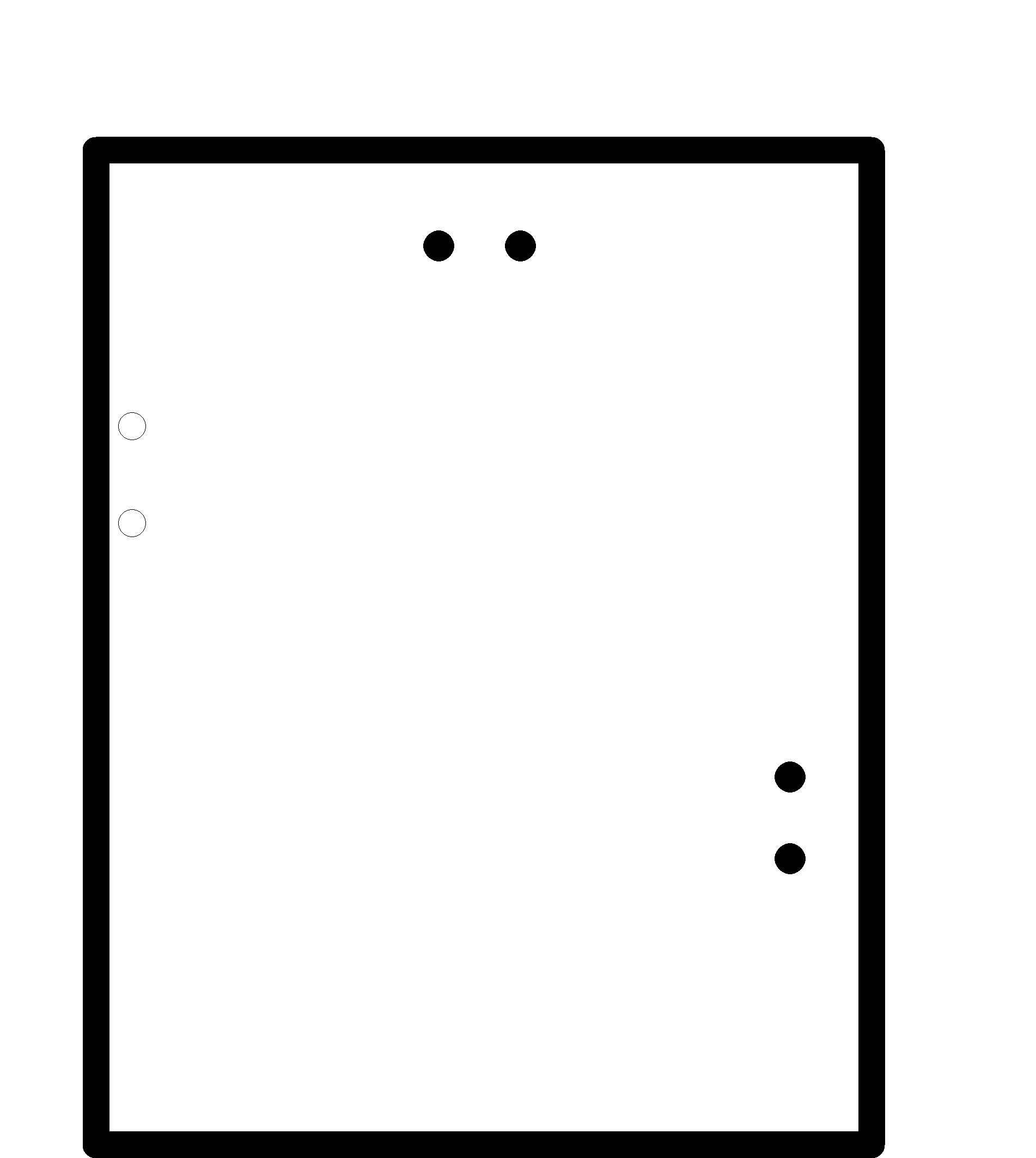
Figuring out the layout and optics for 3D designing the case, I took note of dimensions of the elements going into the optical system.
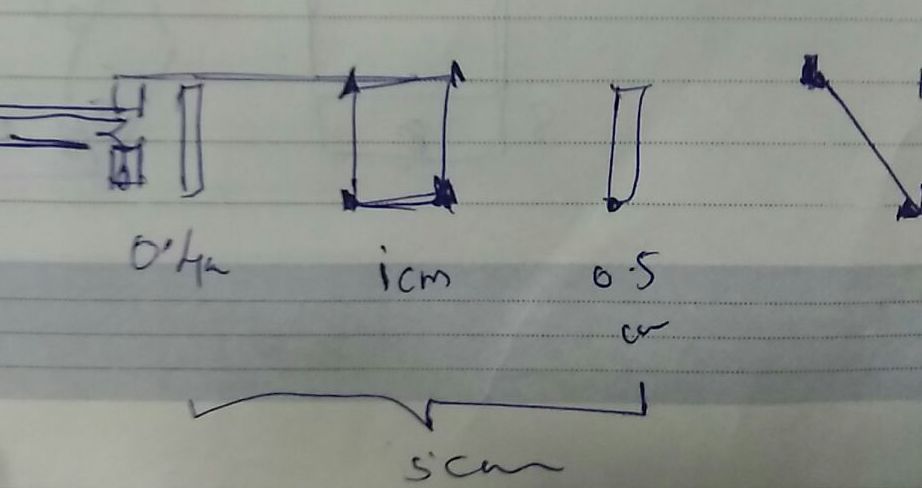
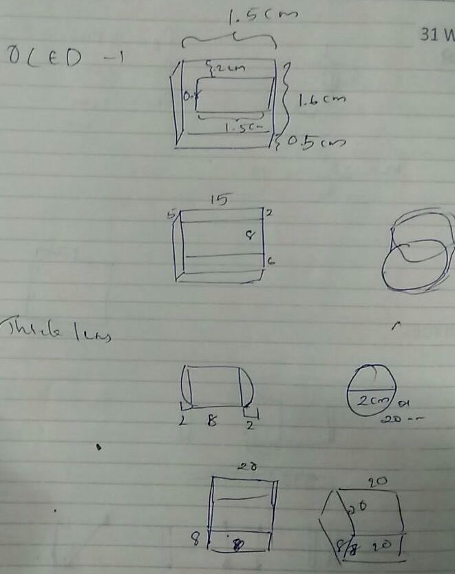
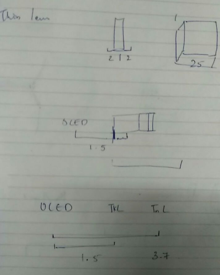
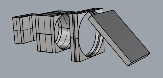
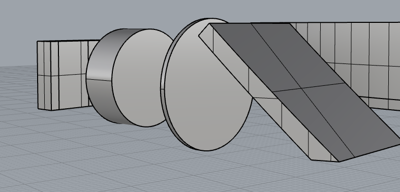
Some screenshots of the optical layout. The thicker hollow blocks are where the lenses would go, and the block on either ends are OLED display and Mirror. With this basic optical design, I created the 3D design for the casing.
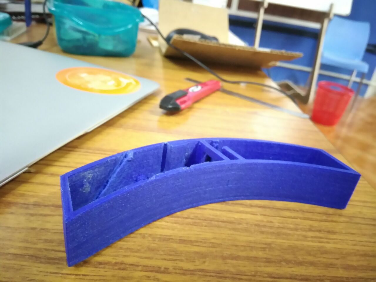
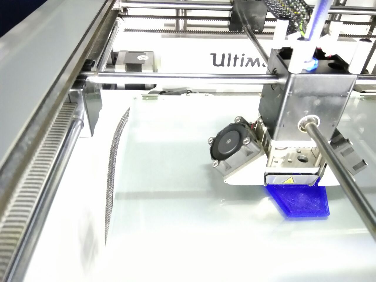
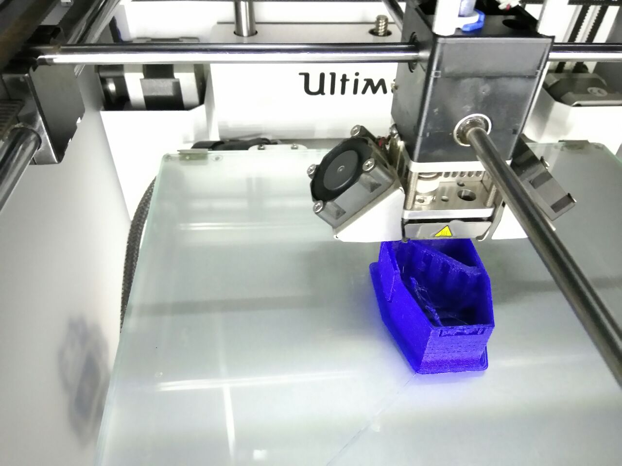
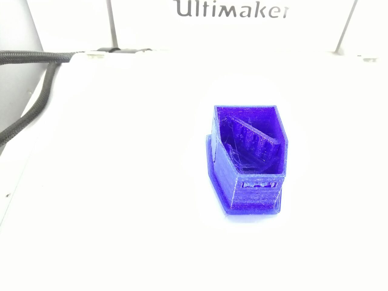
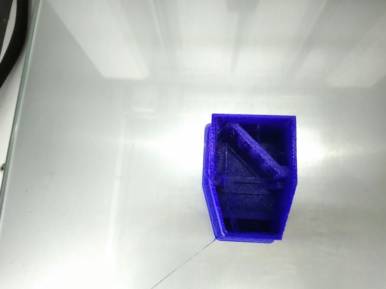
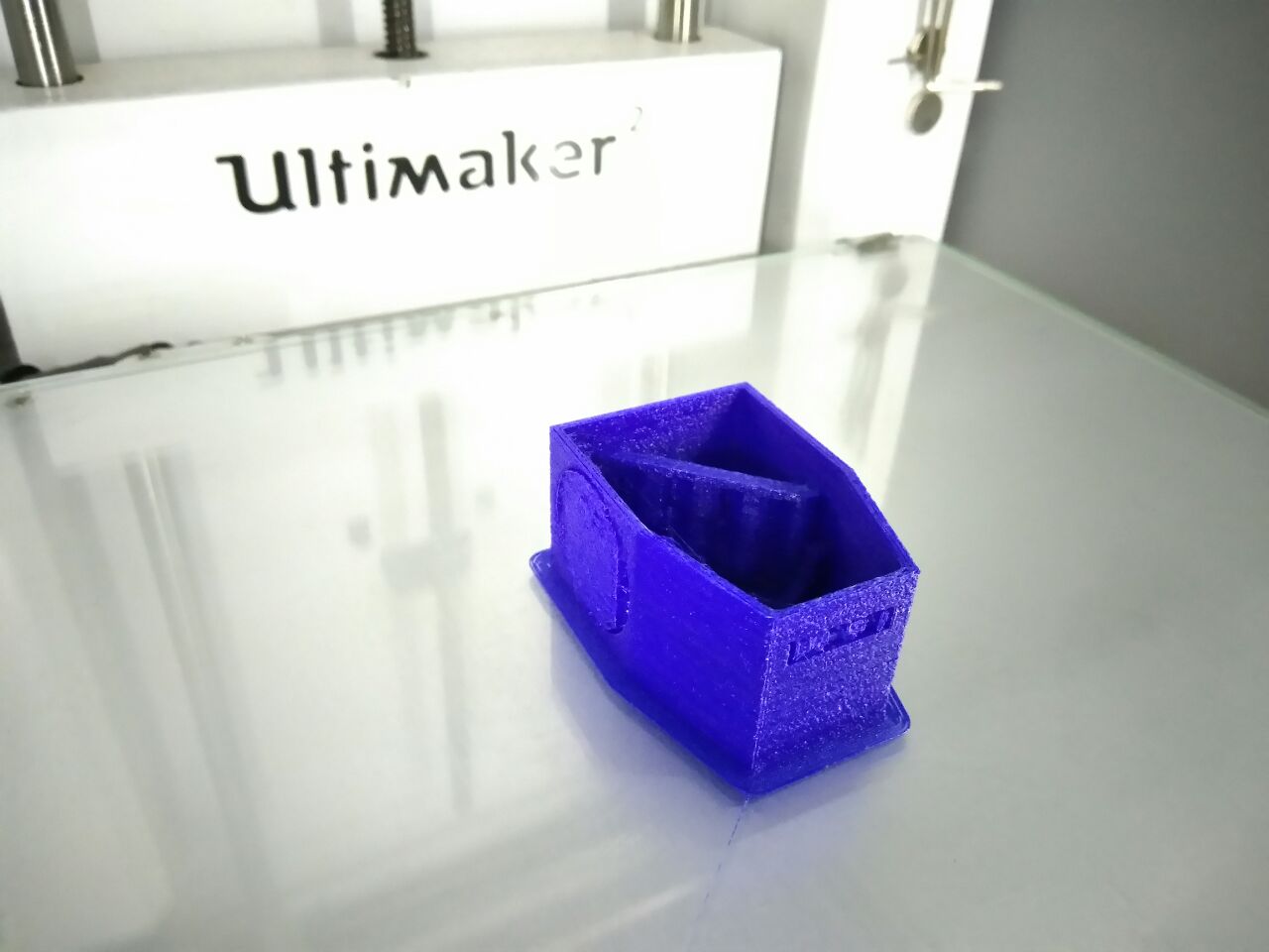
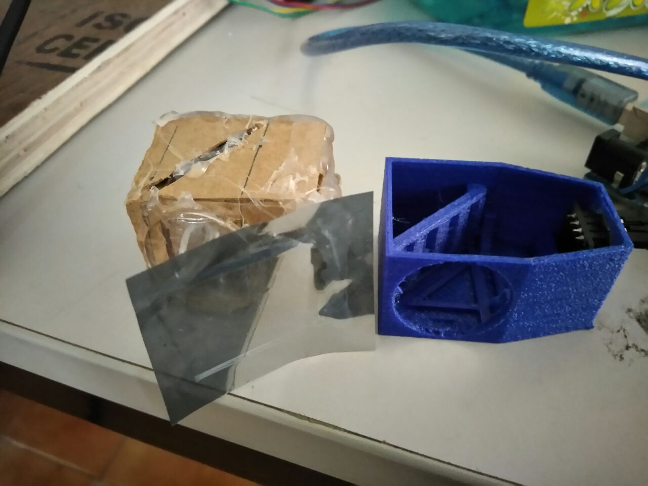
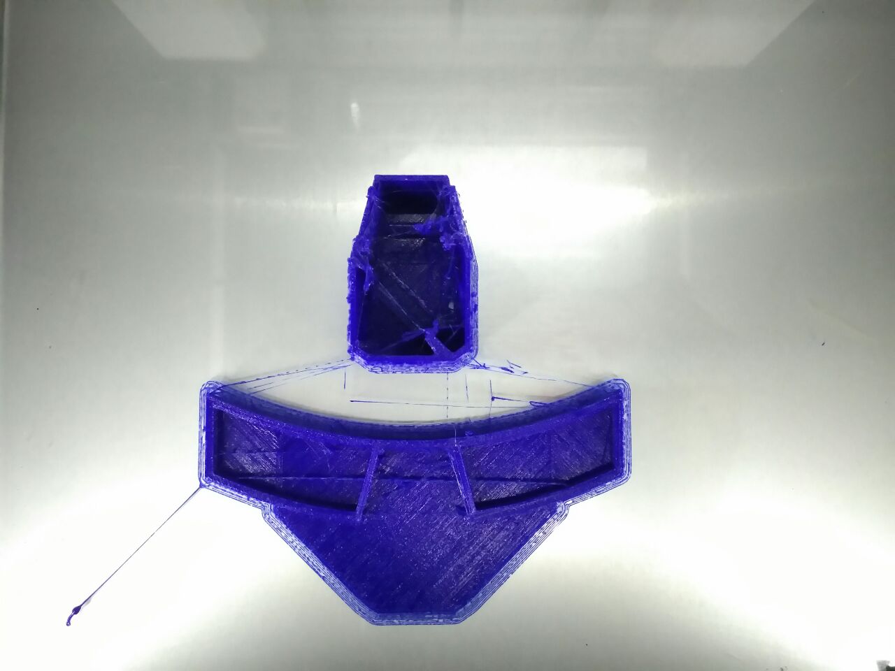
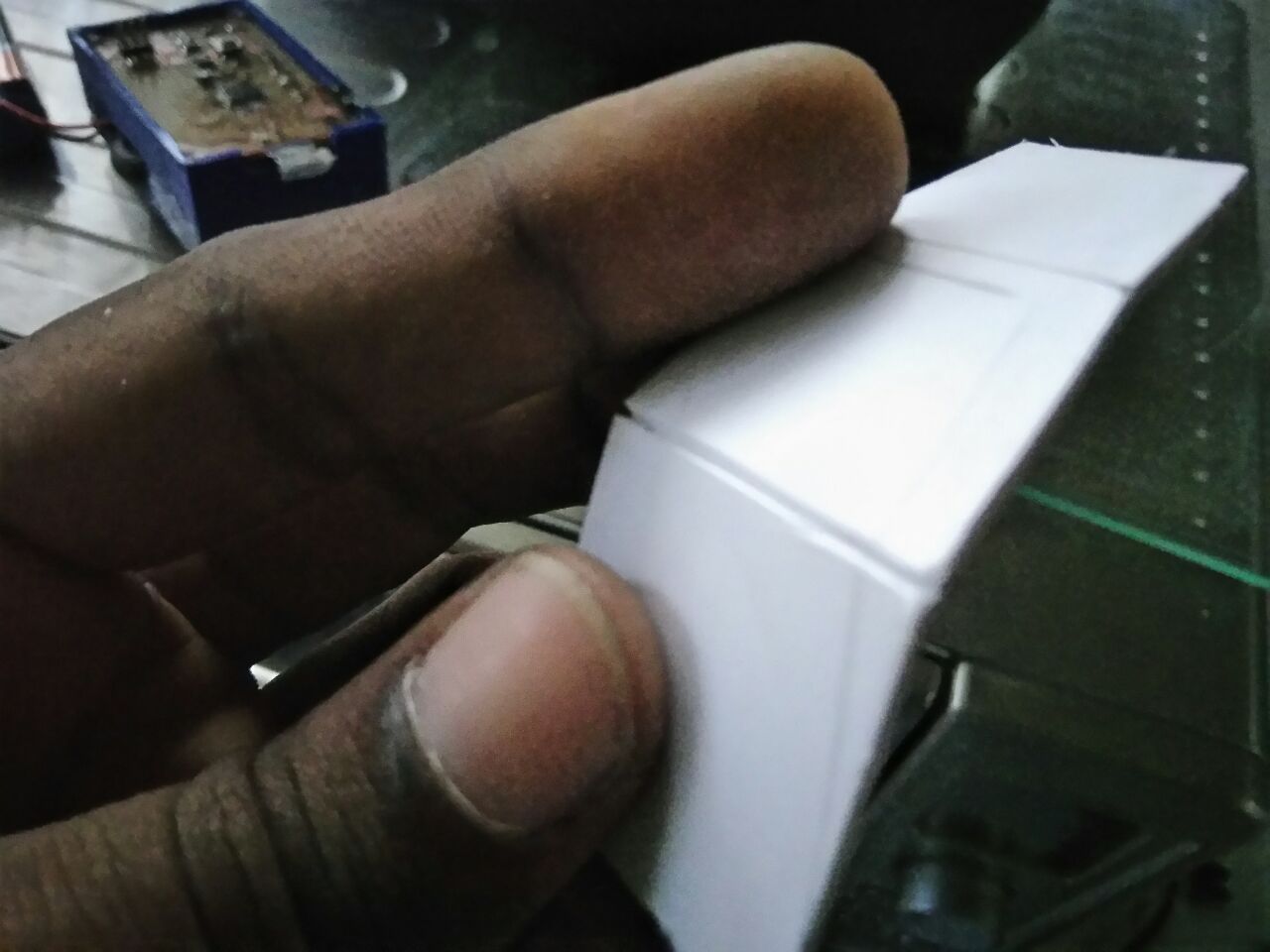
3D printing the design,
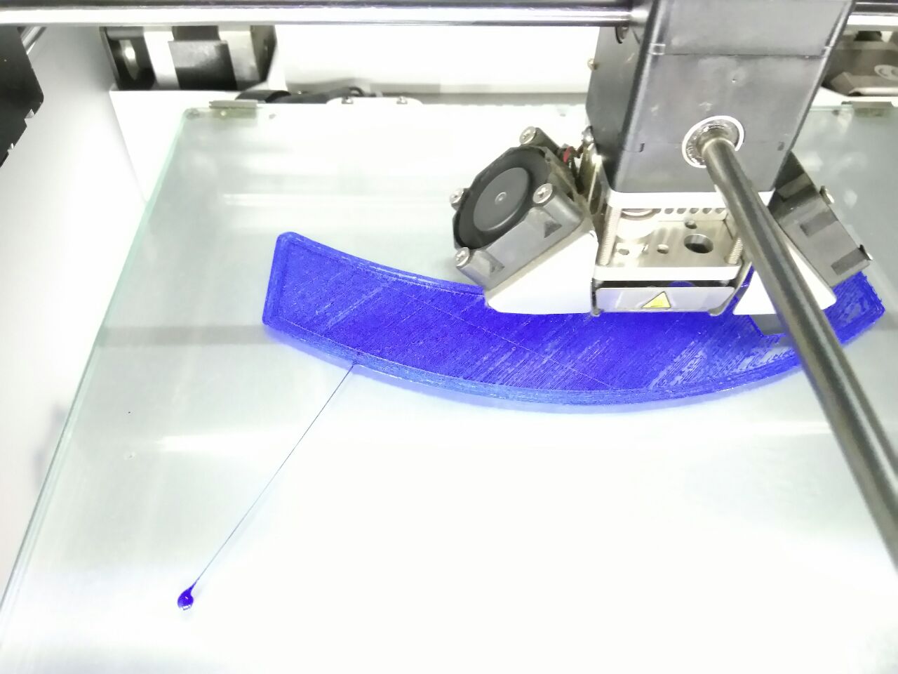
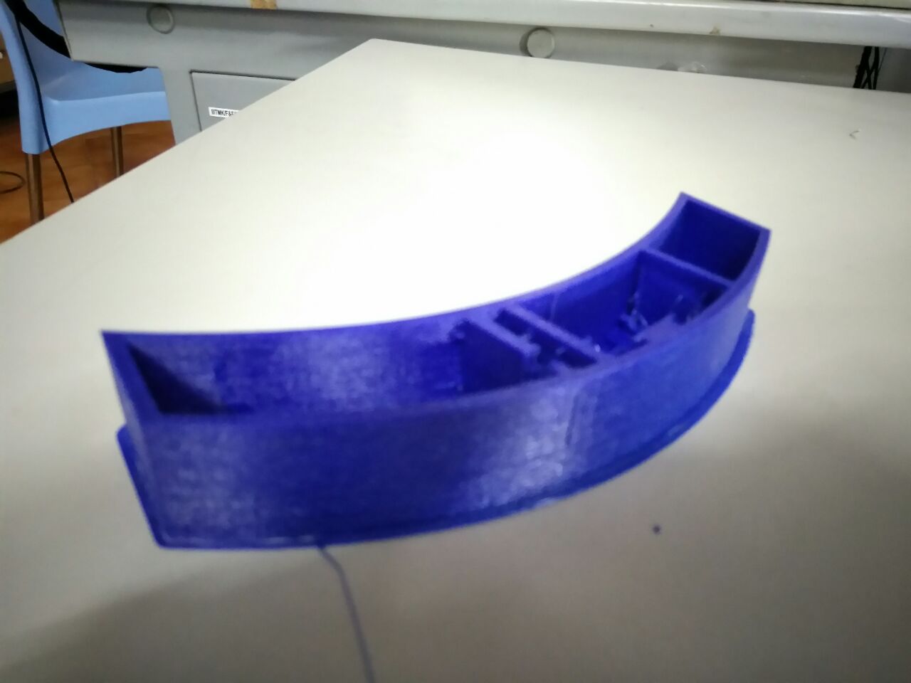
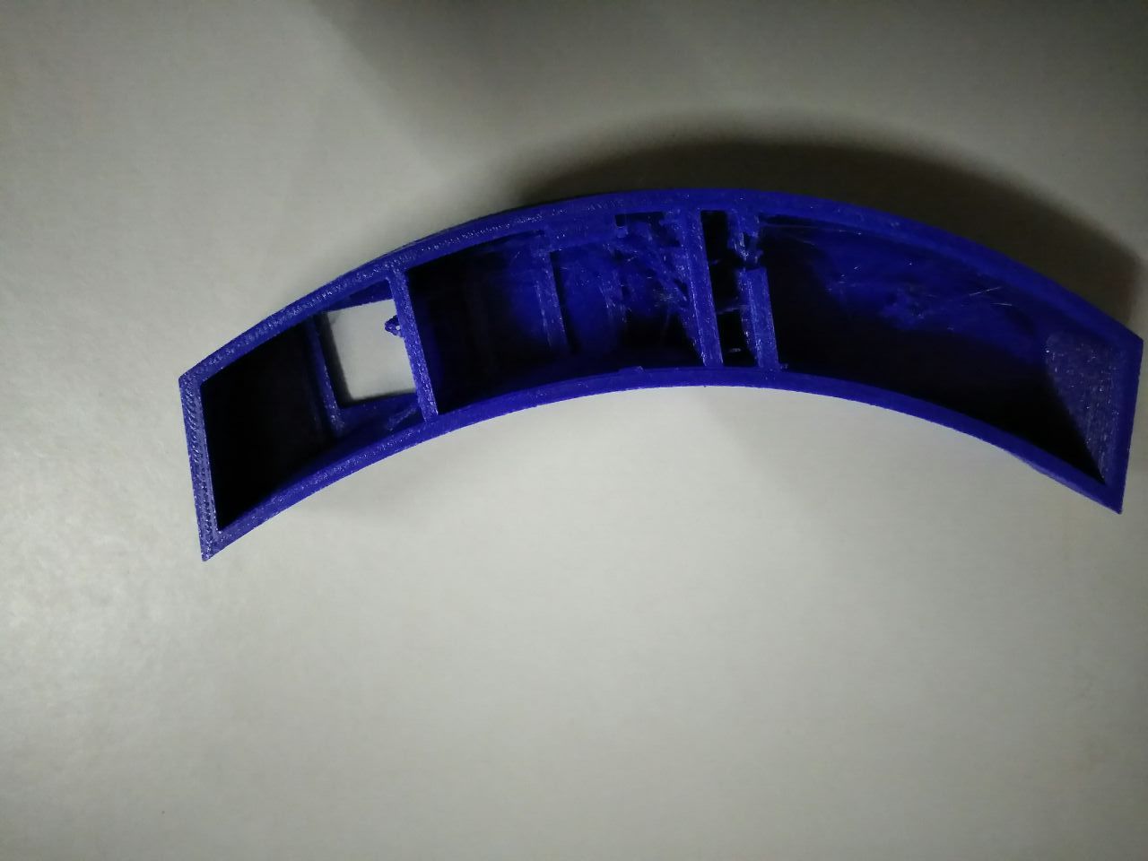
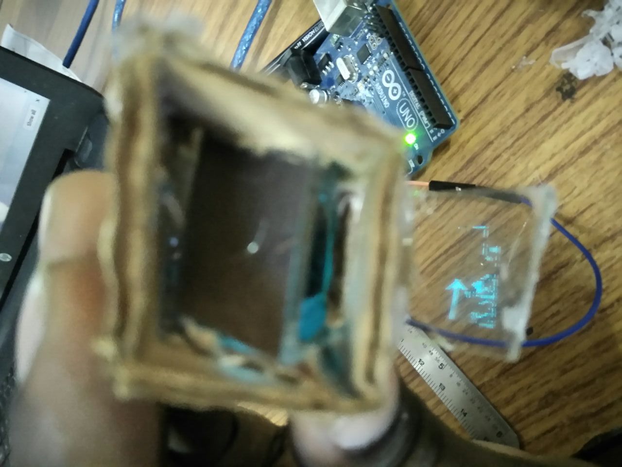
After assembling the OLED and lenses, I could not get the mirror position correctly, so I cut some slots to fit it in.
The following image shows the setup of the optics.
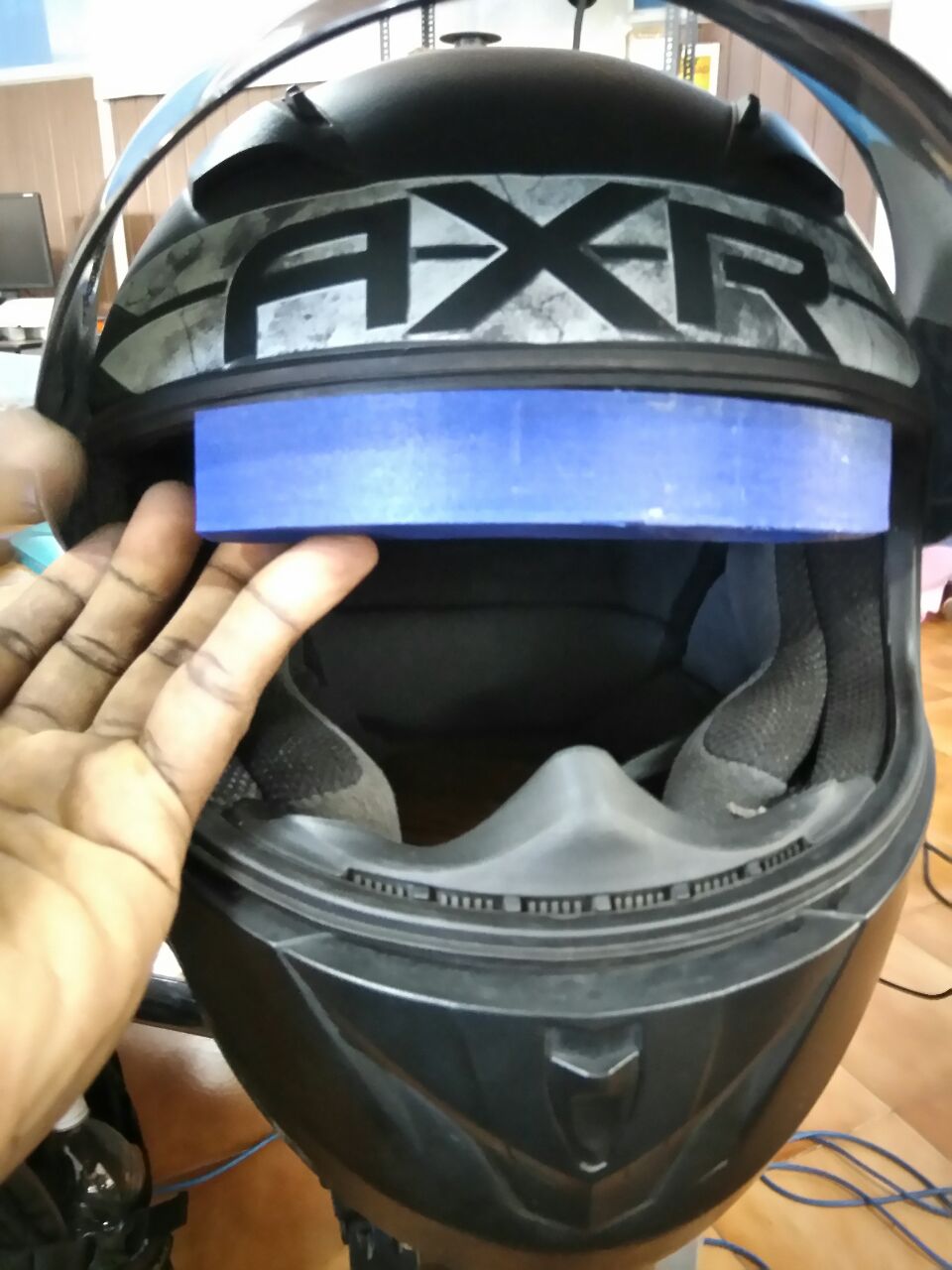
I tried out the case on the helmet. The case fit perfectly, much better than I expected, but there was one major problem, I was loosing lot of peripheral vision.
My observations
Optics actually work, I was able to get OLED contents projected, and did not had to strain to focus on the contents.
Not all the contents from the OLED were projected. I was loosing some screen when it get projected. I researched into it and found its because of barrel distortion. I had to find a replacement to the thick lens to solve this.
Since this is a linear optical setup, with light passing through each lens get diverged, the field of vision keeps on getting reduced with each lens. Thus I was only getting the mid area of the OLED projected.
Second Iteration
I got a lens from VR headset. I was able to substitute the thicker lens with it, but it changed the whole optics system. The optical distance got further reduced which is a good thing, but the magnification also got reduced.
I figured out it would be best to do a cardboard prototype to prove the optics and then 3D print.

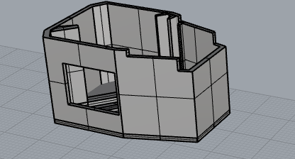
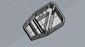
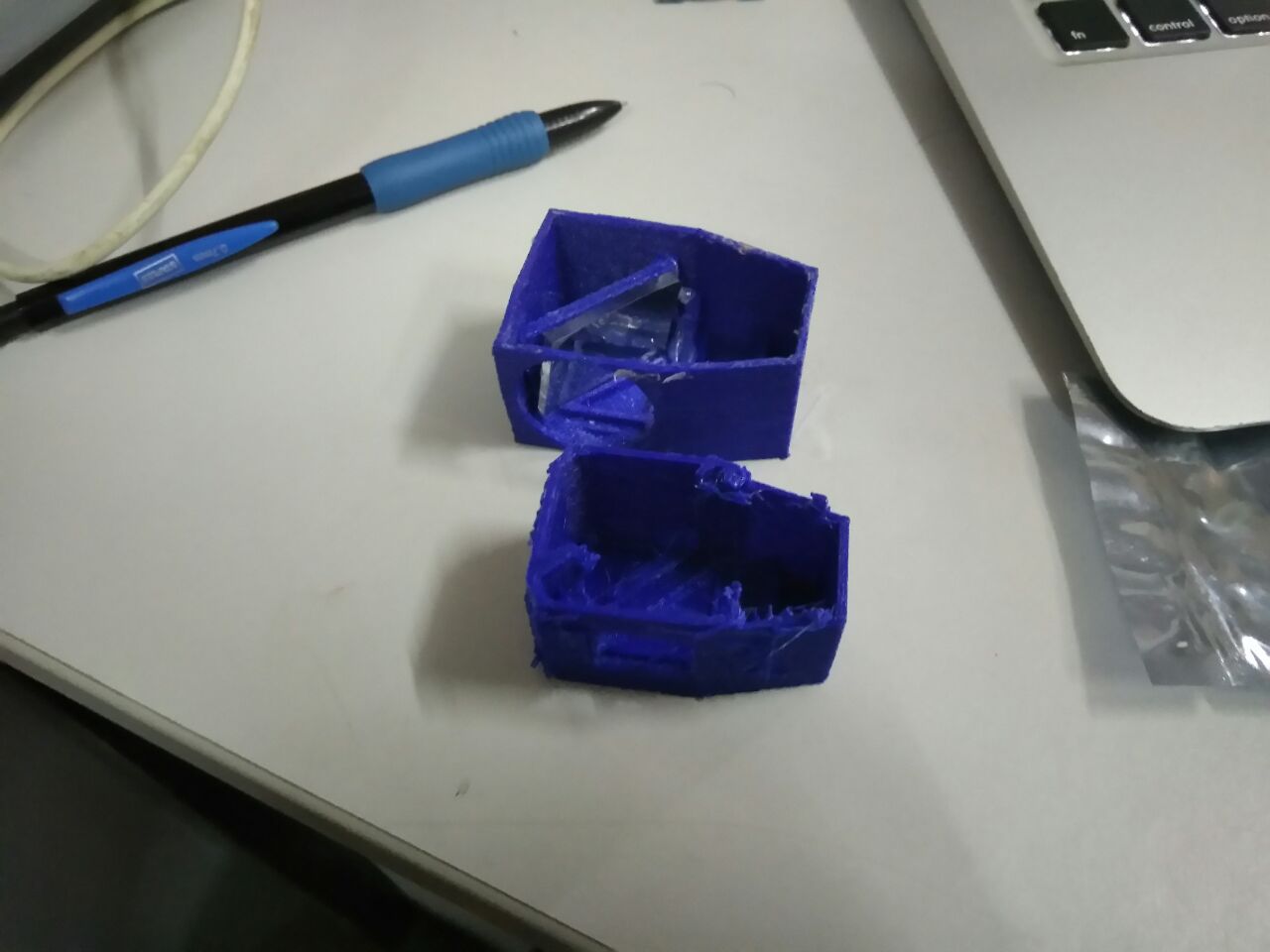
I then proceeded to 3D design by changing the linear structure of the optics,

Then 3D printed the design,
After assembling the optics and the OLED,
My observations
The optics worked, but there was ghost image getting formed. This is because I was using an acrylic mirror which had reflective coating towards the back side of the acrylic. Thus there were dual reflection taking place. I was able to fix it by getting a semi reflective silver sticker and sticking it towards the front side of acrylic where the first reflection takes place. (You can see it in one of the images with cardboard prototype)
The position of the optics casing on the helmet wasn't good, I was still loosing peripheral vision.
Though I was able to get all the contents of the OLED projected onto the eye in my cardboard prototype, the 3D designed case had a bigger outlet for projection, which also started projecting the light coming from the first lens before hitting the mirror. This is because of the first lens projects a bigger image of which not all the light rays fall onto the mirror. Also the outlet being big, gives the wearer distorted image.
Third Iteration
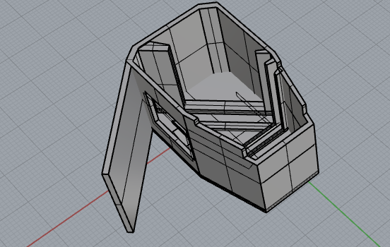
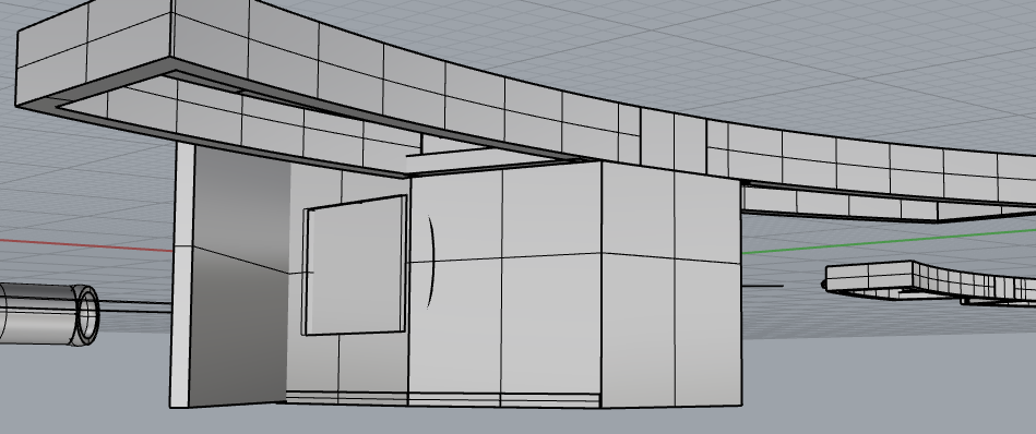
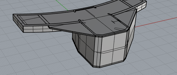
In this iteration, I had to reduce the overall size of the optics case, reduce the size of image projected from the first lens and also reduce the projection outlet.
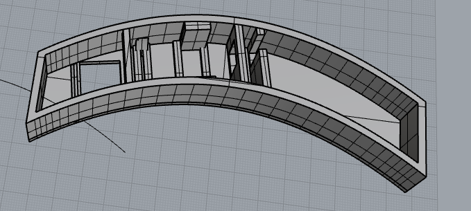
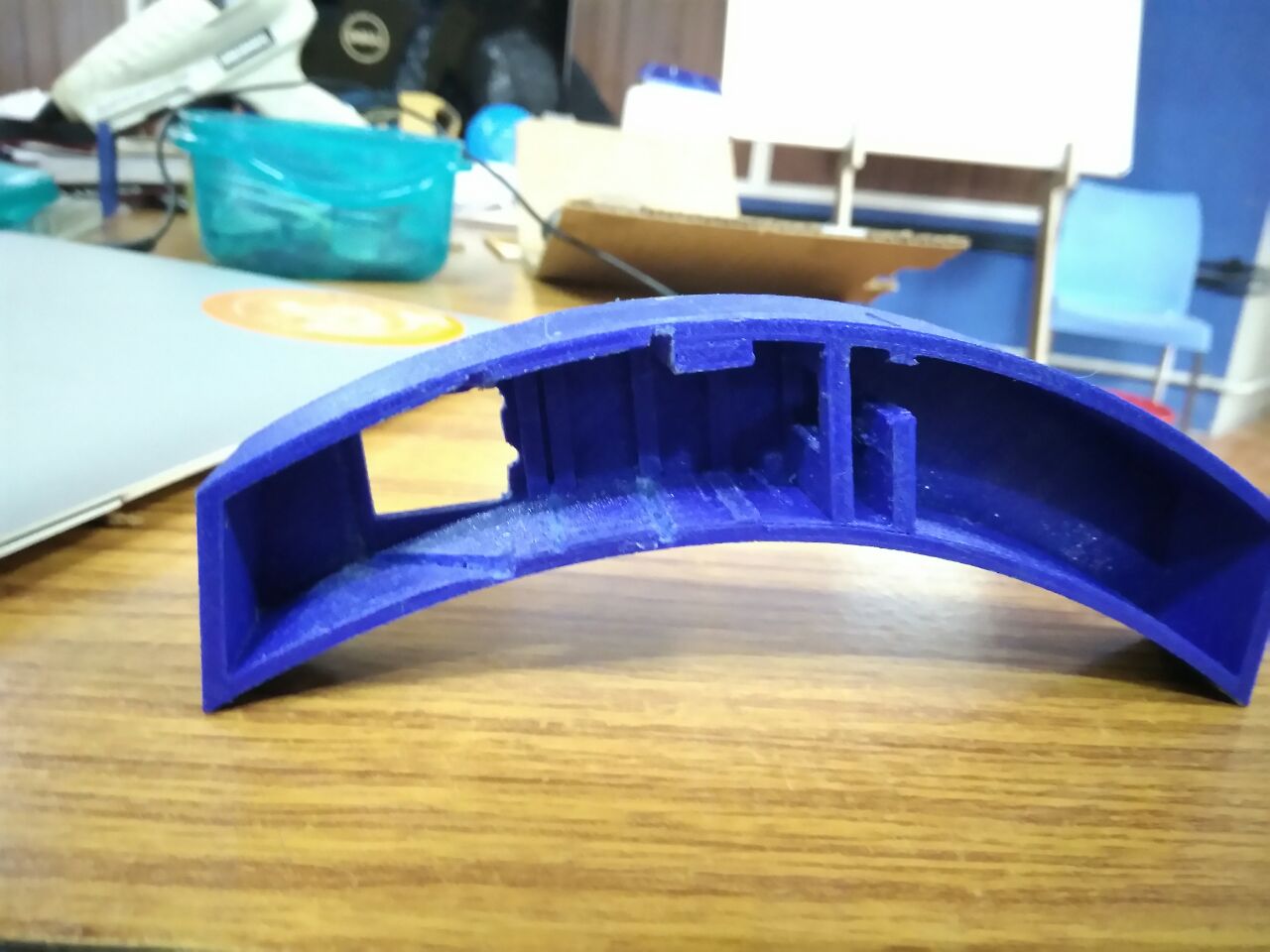
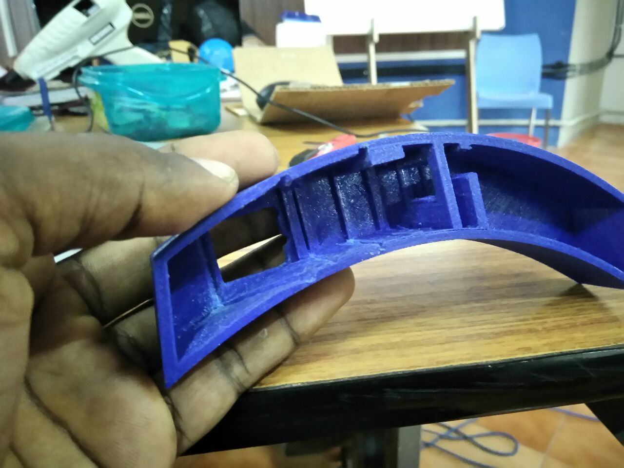
I also made an integrated lid + case for electronics part which was only 1cm in height. The lid was supposed to anchor into the helmet and hold up the electronics and optics case.
Off towards the 3D printer..!!
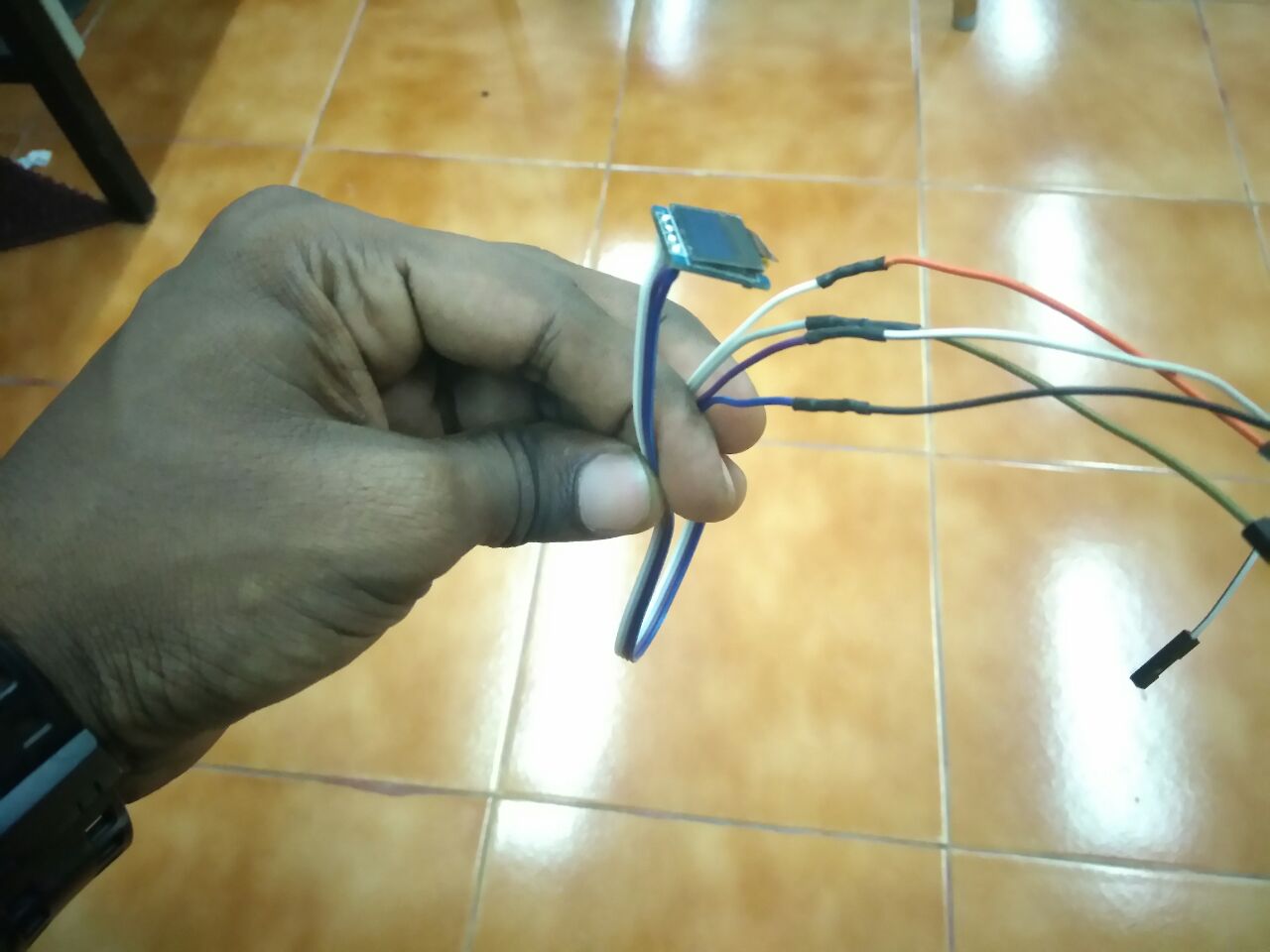
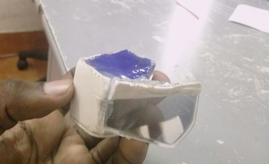
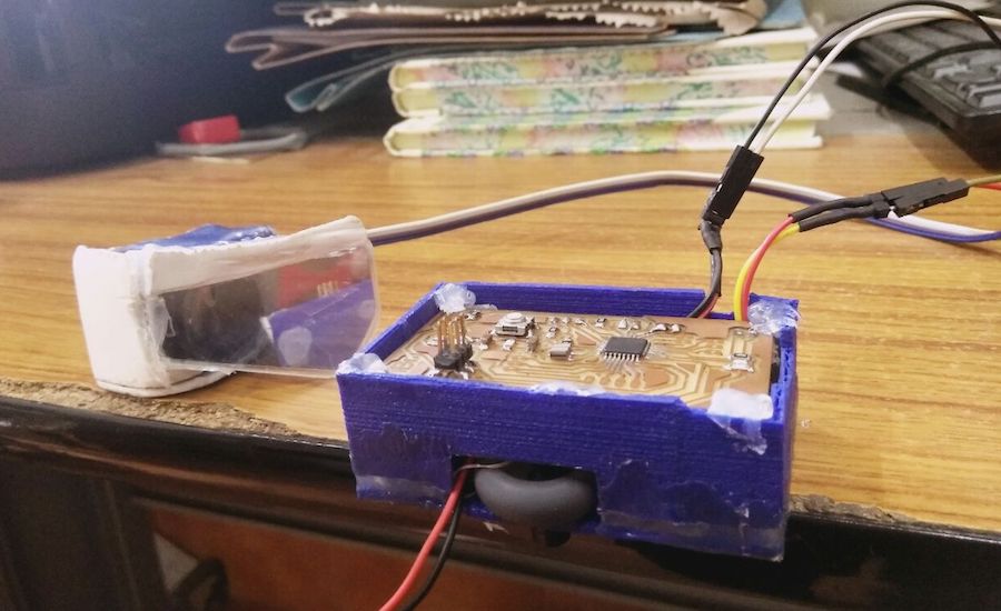
Desoldered the OLED pins and drew wires from it. After setting up the optics I enclosed it using the lid, well part of the lid. I cut out the wings because the electronics wont anyway fit into it.
Since I reduced the optical distance to avoid getting distorted images, I could no longer fit the second lens inside the optics case without cutting the lens. I did not want to go through that step, so I hot glued it on the outside.
Now started the great affinity I have for hot glueing.. I glued everything inside the optics case to outside. I mean everything..!!
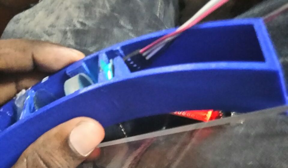
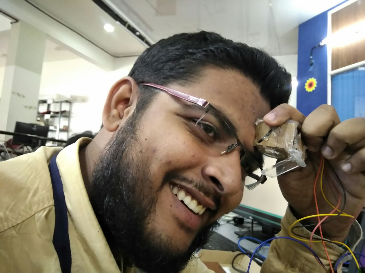
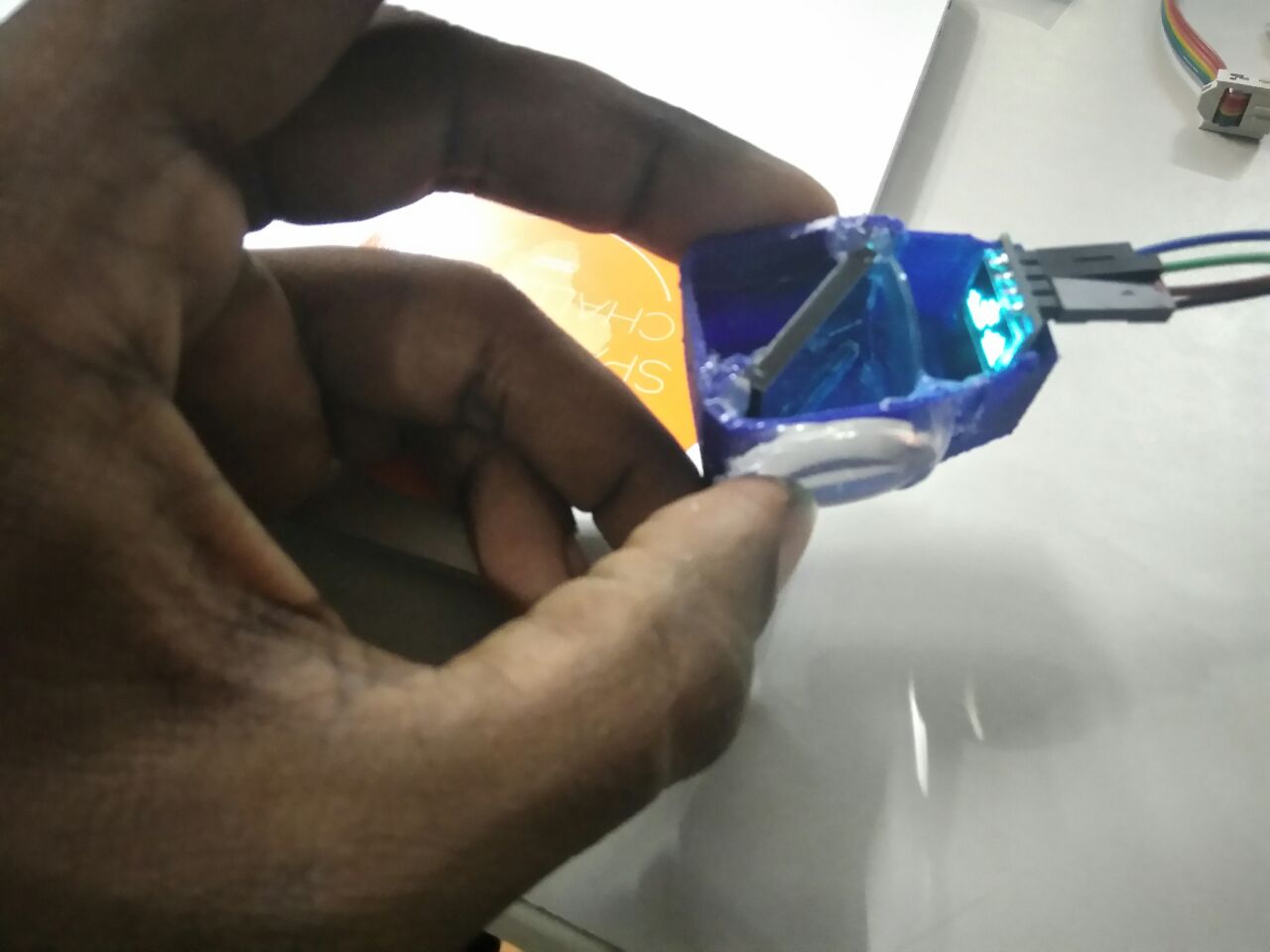
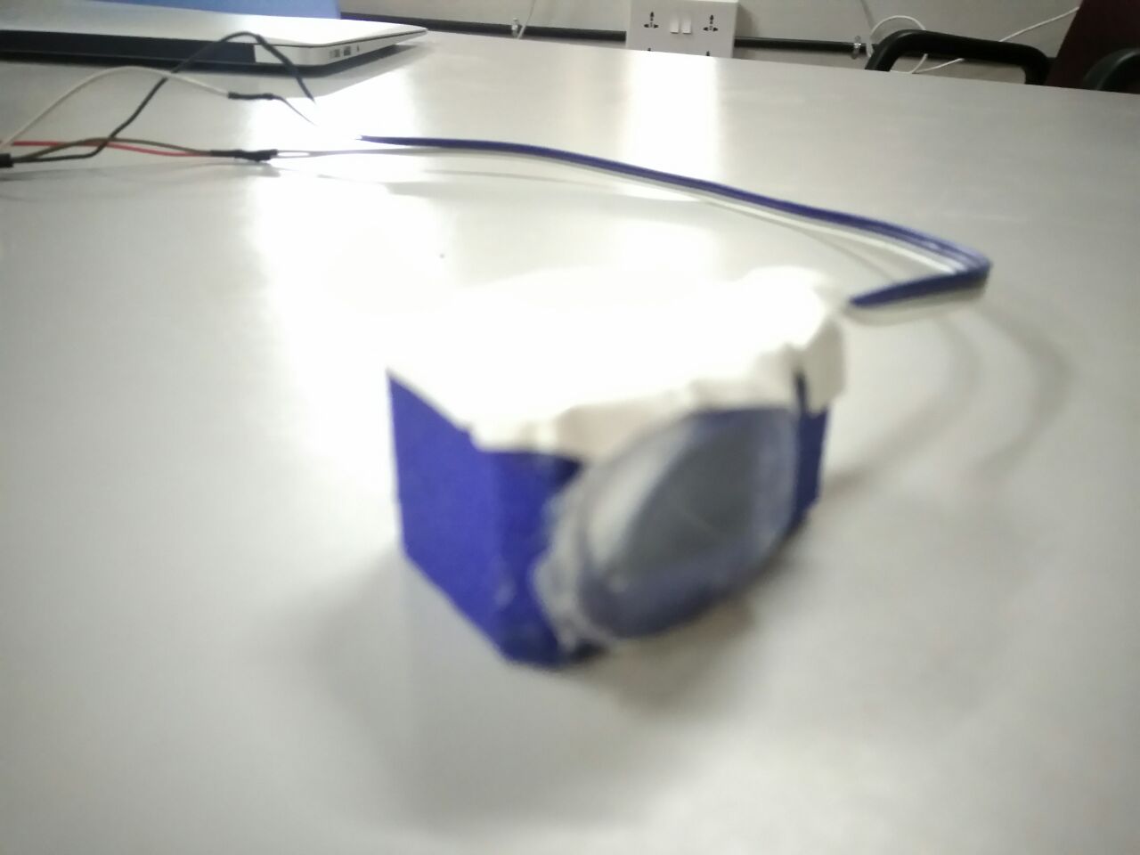
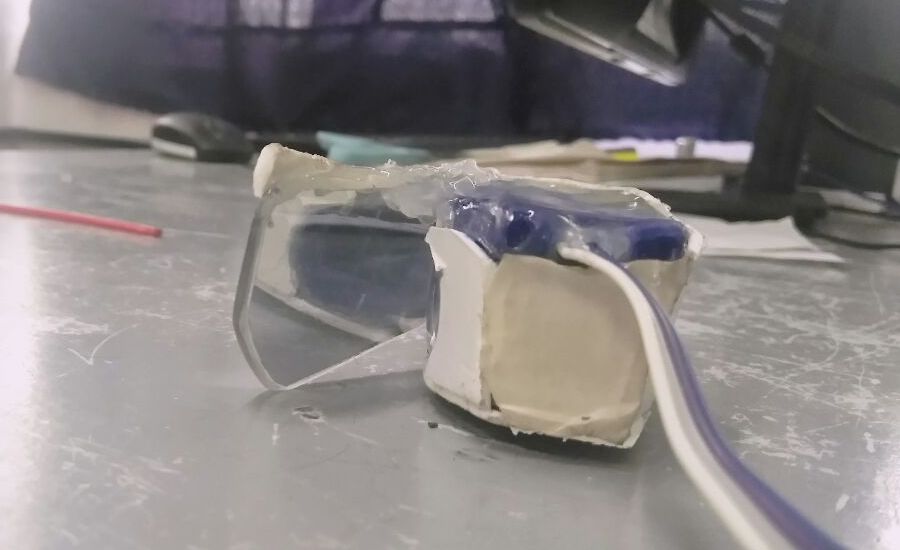
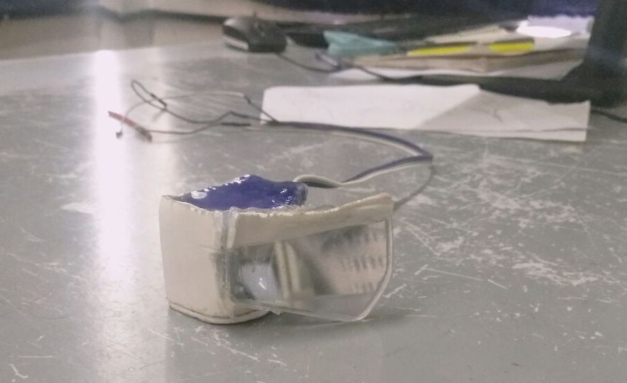
Testing out the setup,
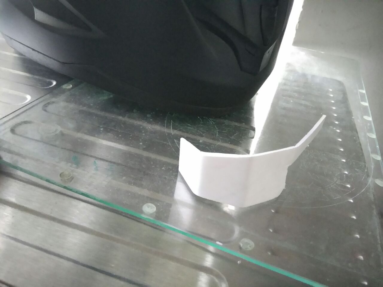
Now that the optics where all figured out, I finished off the setup by cutting the reflector glass in acrylic in the following shape, and sticking the surface thats toward the eye with semi reflective sticker. This is to avoid ghost image formation.
My observations
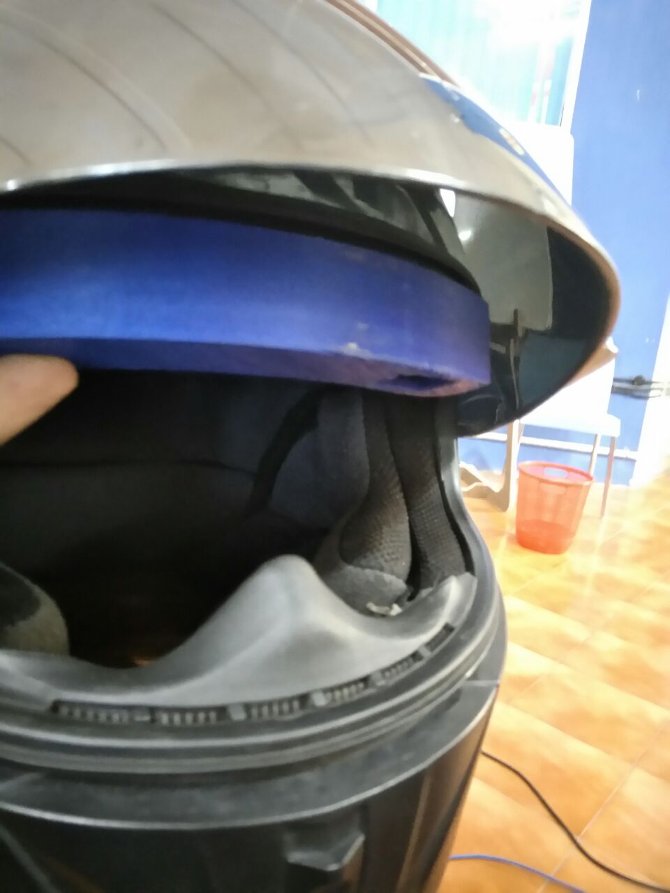
The optics was position in such a way that good peripheral vision was retained.
I could see the entire screen, eventhough thats because I reduced some magnification but it still get projected nicely on my eye.
In direct sunlight, I could not view the augmented display but can see it better if I close my reflective visor as well.
Electronics and Programming
Eventhough my documentation till now did not speak about electronics part, I was dealing with it along the same timeline.
Like I said earlier, I did partial work in my interface and application programming week. That is controlling the OLED messages using bluetooth module. I was able to add images as bitmap and display it. Using control signals from bluetooth I could toggle the display screens.
This documentation will only deal with what I have continued from the application programming week.
So what I already have in possession was a sakshakit that I milled and programmed which is controllable via bluetooth using control signals.
What I wanted to add to this is a rotary encoder and use it to change the display screens. Also power the board using a battery.
I just noticed that I did not take any screenshots or snaps of the electronics and programming work I did.
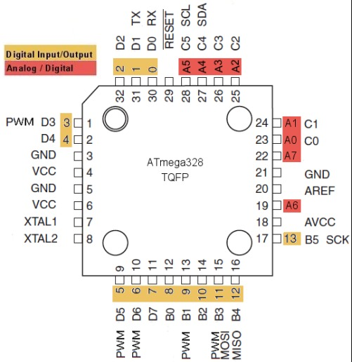
I took apart a computer mouse for its rotary encoder. I connected the pins accordingly onto the saksha kit and ran the following code. The interrupt pins for atmega328p is 2 and 3. I got confused that pin nos 32 and 1 were shown as interrupts in the schematic diagram. But its actually only 2 and 3.
The hidden lines just increments and decrements the value of encoder0Pos based on the direction of rotation. It lights up an led when interrupt happens. I tweeked the code a lot to make it work in satshakit. This is the end file when I got it working.
//#define encoder0PinA  2
//#define encoder0PinA  32
//#define encoder0PinB  3
//#define encoder0PinB  1
const byte encoder0PinB = 2;
//volatile byte state = LOW;
int ledpin = 13;

void setup() {
  // put your setup code here, to run once:
//  pinMode(encoder0PinA, INPUT);
//  digitalWrite(encoder0PinA, HIGH);       // turn on pull-up resistor
  pinMode(encoder0PinB, INPUT);
  digitalWrite(encoder0PinB, HIGH);       // turn on pull-up resistor

//  attachInterrupt(0, doEncoder, FALLING);
attachInterrupt(digitalPinToInterrupt(encoder0PinB), doEncoder, FALLING);
//  attachInterrupt(1, doEncoder, CHANGE);
  // attachInterrupt(0, doEncoder, CHANGE);  // encoder pin on interrupt 0 - pin 2
  Serial.begin (9600);
//  Serial.println("start");
pinMode(ledpin, OUTPUT);
digitalWrite(ledpin, LOW);
}

void loop() {
  // put your main code here, to run repeatedly:

}

void doEncoder() {
  /* If pinA and pinB are both high or both low, it is spinning
   * forward. If they're different, it's going backward.
   *
   * For more information on speeding up this process, see
   * [Reference/PortManipulation], specifically the PIND register.
   */
   digitalWrite(ledpin, HIGH);
   delay(1000);
   digitalWrite(ledpin, LOW);
//  if (digitalRead(encoder0PinA) == digitalRead(encoder0PinB)) {
//    encoder0Pos --;
//  }
//  else {
//    encoder0Pos ++;
//  }
//
//  Serial.println (encoder0Pos, DEC);
}
After making sure the rotary encoder works, I tested it with the OLED code to toggle the screens. The following is the amalgamation of both the rotary encoder code and as well as the code I did on application programming week. I also tweeked a lot to get it to function the way I wanted. Anyway since this being an end file, I know it works.
/* read a rotary encoder with interrupts
   Encoder hooked up with common to GROUND,
   encoder0PinA to pin 2, encoder0PinB to pin 4 (or pin 3 see below)
   it doesn't matter which encoder pin you use for A or B

   uses Arduino pull-ups on A & B channel outputs
   turning on the pull-ups saves having to hook up resistors
   to the A & B channel outputs

*/

//#define encoder0PinA  2
const byte encoder0PinA = 2;
//#define encoder0PinB  3
const byte encoder0PinB = 3;

#include < Adafruit_SSD1306.h>


#define OLED_RESET 4
Adafruit_SSD1306 display(OLED_RESET);

//uint8_t bmp[] = {};
static const unsigned char PROGMEM logo16_glcd_bmp[] =
{ 0x00, 0x00, 0x00, 0x00
  , 0x00, 0x00, 0x00, 0x00
  , 0x00, 0x00, 0x02, 0x00
  , 0x00, 0x00, 0x03, 0x00
  , 0x00, 0x00, 0x03, 0x80
  , 0x00, 0x00, 0x01, 0xc0
  , 0x00, 0x00, 0x01, 0xe0
  , 0x0f, 0xff, 0xff, 0xf8
  , 0x0f, 0xff, 0xff, 0xf8
  , 0x00, 0x00, 0x01, 0xe0
  , 0x00, 0x00, 0x01, 0xc0
  , 0x00, 0x00, 0x01, 0x80
  , 0x00, 0x00, 0x03, 0x00
  , 0x00, 0x00, 0x02, 0x00
  , 0x00, 0x00, 0x00, 0x00
  , 0x00, 0x00, 0x00, 0x00
  , 0x00, 0x00, 0x00, 0x00
  , 0x00, 0x00, 0x00, 0x00

};

#if (SSD1306_LCDHEIGHT != 32)
#error("Height incorrect, please fix Adafruit_SSD1306.h!");
#endif


volatile unsigned int encoder0Pos = 5000;
int diffValue = 0;
int ledpin = 13; // led on D13 will show blink on / off
char ScreenNo, CharData;
String Data;
char ScreenList[] = {'a', 'f', 'g'};
int ScreenIndex = 0;
//unsigned char  *ImageList[1] = {};
//unsigned char ImageByte;

void setup() {


  pinMode(encoder0PinA, INPUT);
  digitalWrite(encoder0PinA, HIGH);       // turn on pull-up resistor
//  pinMode(encoder0PinB, INPUT);
//  digitalWrite(encoder0PinB, HIGH);       // turn on pull-up resistor

  attachInterrupt(digitalPinToInterrupt(encoder0PinA), doEncoder, FALLING);
  Serial.begin (9600);
//  Serial.println("start");                // a personal quirk
  display.begin(SSD1306_SWITCHCAPVCC, 0x3C);
  pinMode(ledpin, OUTPUT);
  digitalWrite(ledpin, LOW);
}

void loop(){
  if (Serial.available()) {
    ScreenNo = Serial.read();
    DisplayScreen(ScreenNo);
  }
  else
  {
    diffValue = encoder0Pos - 5000;
    if(abs(diffValue) > 5)
    {

      ScreenIndex ++;
      if (ScreenIndex > sizeof(ScreenList) - 1 ||  ScreenIndex < 0)
        ScreenIndex = 0;

      ScreenNo = ScreenList[ScreenIndex];
      DisplayScreen(ScreenNo);
      delay(250);
      encoder0Pos = 5000;
    }
  }
//  digitalWrite(ledpin, HIGH);
//  delay(1000);
//  digitalWrite(ledpin, LOW);
//  delay(1000);
}

void DisplayScreen(char ScreenNo)
{
  switch(ScreenNo) {
      case 'a': digitalWrite(ledpin, 1);
              display.clearDisplay();   // Clear the buffer.
              display.drawBitmap(0, 0,  logo16_glcd_bmp, 32, 32, 1);
              display.display();
//              delay(100);
              break;
      case 'f': digitalWrite(ledpin, 0);
              display.clearDisplay();   // Clear the buffer.
              display.setTextSize(1);
              display.setTextColor(WHITE);
              display.setCursor(0, 0);
              display.println("#Distance");
              // display.setCursor(20,0);
              // display.println(10);
              display.setTextSize(1);
              display.setCursor(0, 10);
              display.println("#Address");

              display.display();
//              delay(100);
              break;
       case '%':
              Data = "";
              CharData = Serial.read();
              while(CharData != '#')
              {
                Data.concat(CharData);
                CharData = Serial.read();
                delay(10);
              }
              digitalWrite(ledpin, 0);
              display.clearDisplay();   // Clear the buffer.
              display.setTextSize(1);
              display.setTextColor(WHITE);
              display.setCursor(0, 0);
              display.println("Data: ");
              // display.setCursor(20,0);
              // display.println(10);
              display.setTextSize(1);
              display.setCursor(0, 10);
              display.println(Data);

              display.display();
//              delay(100);
              break;
       case 'g':
              digitalWrite(ledpin, 0);
              display.clearDisplay();   // Clear the buffer.
              display.setTextSize(1);
              display.setTextColor(WHITE);
              display.setCursor(0, 0);
              display.println("Data: ");
              // display.setCursor(20,0);
              // display.println(10);
              display.setTextSize(1);
              display.setCursor(0, 10);
              display.println(diffValue);

              display.display();
//              delay(100);
      default: break;
    }
}

void doEncoder() {
  /* If pinA and pinB are both high or both low, it is spinning
   * forward. If they're different, it's going backward.
   *
   * For more information on speeding up this process, see
   * [Reference/PortManipulation], specifically the PIND register.
   */
//   delay(100);
   digitalWrite(ledpin, HIGH);
  if (digitalRead(encoder0PinA) == digitalRead(encoder0PinB)) {
    encoder0Pos --;
  }
  else {
    encoder0Pos ++;
  }
  digitalWrite(ledpin, LOW);
//  Serial.println (encoder0Pos, DEC);
}
Now that the programming works have been documented, I will get towards the electronics work I did.
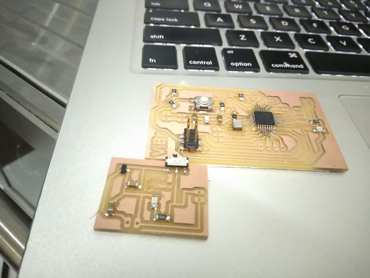
I started with the satshakit that I created on application programming week, I used that for most part of the project work. Since I wanted to add power board to it, I tried to add both the power board and satshakit board into a single board.
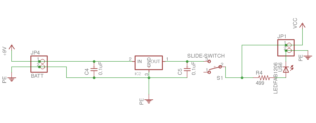
The schematic of the power circuit. This is an end file, but there was a diode there in the powerboard which would not let reverse current flow into the voltage regulator. But apparently, since there was a diode I could not program the board either, Vcc was blocked by this diode. Also the volatage regulator was burning up as well.
The following is the a screenshot I took when I was integrating both the satshakit as well as this power board.
Funny thing, I started that design here, but then ditched this because it was getting crowded. In this design I tried both top and bottom layer.
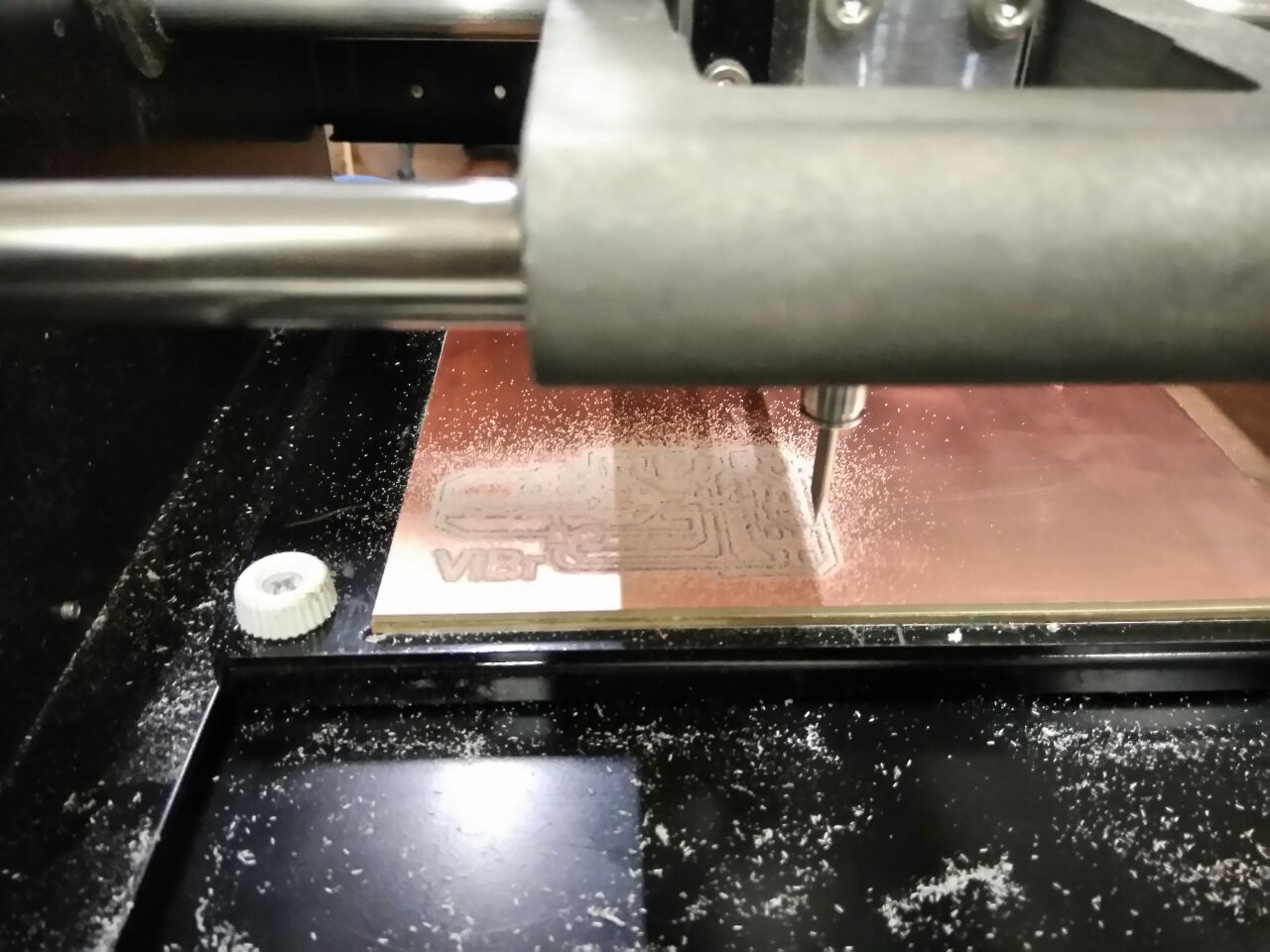
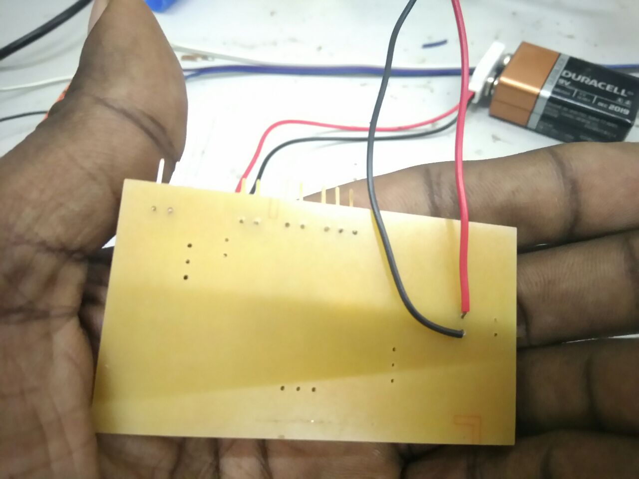
Started milling the board as well.
After assembling the components, I tried testing by programming the board which did not work. The details on why it did not work is because there was a diode, Vcc was blocked by this diode. Also the volatage regulator was burning up as well.
I later desoldered the components and remilled the satshakit and kept the power board as a separate unit as well.


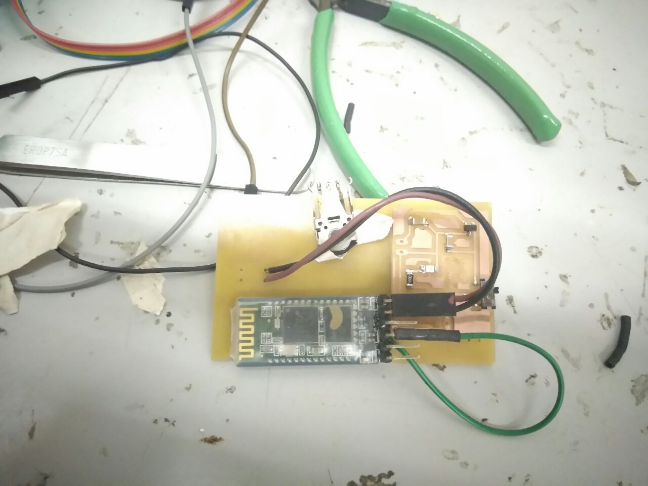
Everything was working alright, I was able to program the board, I tried the default blinking code to make sure everything is working, I tried bluetooth connected blink code as well, which also worked. In this case, I was powering the board via my laptop and disconnected my power board.
Then I repeated the same with power board connected and I was powering the board using battery. I was not able to get the bluetooth module powered, so I tried debugging. The voltage drop at the bluetooth where less that 2.8V and for the OLED also its the same. I was using a 3.3 V voltage regulator.
I desoldered the 3.3 V voltage regulator and replaced it with a 5V regulator. Now when I connected, I was able to get the OLED working, and the voltage drop across it was found somewhere to be around 3.2V. But the bluetooth module was still not getting powered from the battery. I checked the voltage drop across it and found it to be around 2.8 V.
I tried debugging and found that shorting the diode fixed the voltage drop issue. I used a wire to short across the diode. Now both the OLED and bluetooth were getting powered.
Now another issue arised, I was not able to get bluetooth communication working properly when I connected to power board. The bluetooth connection RX, TX was able to receive commands when the board is powered to the laptop. And it stop working when I connected to power board.
I was able to figure it out by using the following circuit. What I need was to add a level shifter circuit,
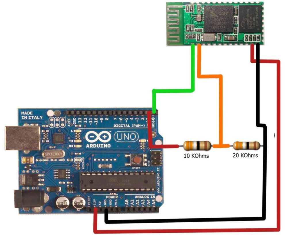
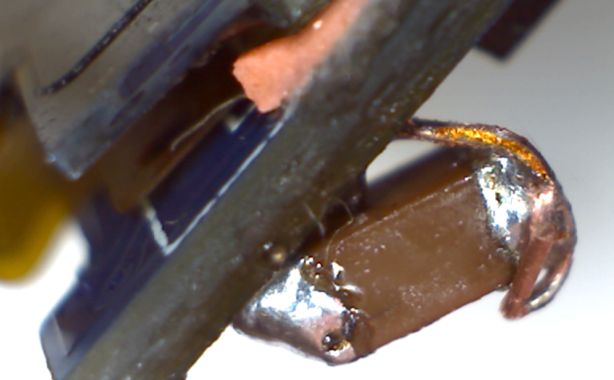
I tried soldering 10k ohm smd components to the existing satshakit board.
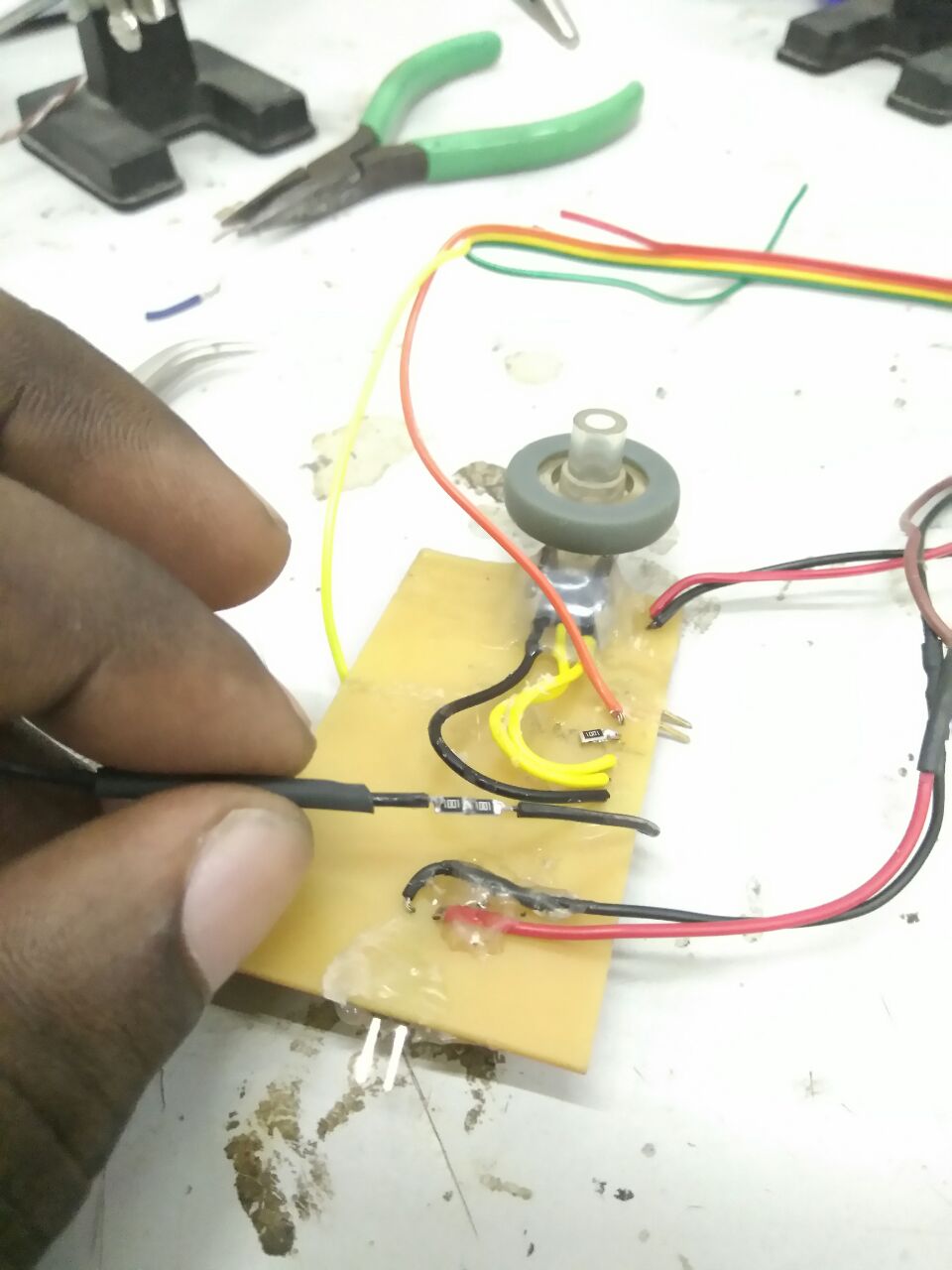
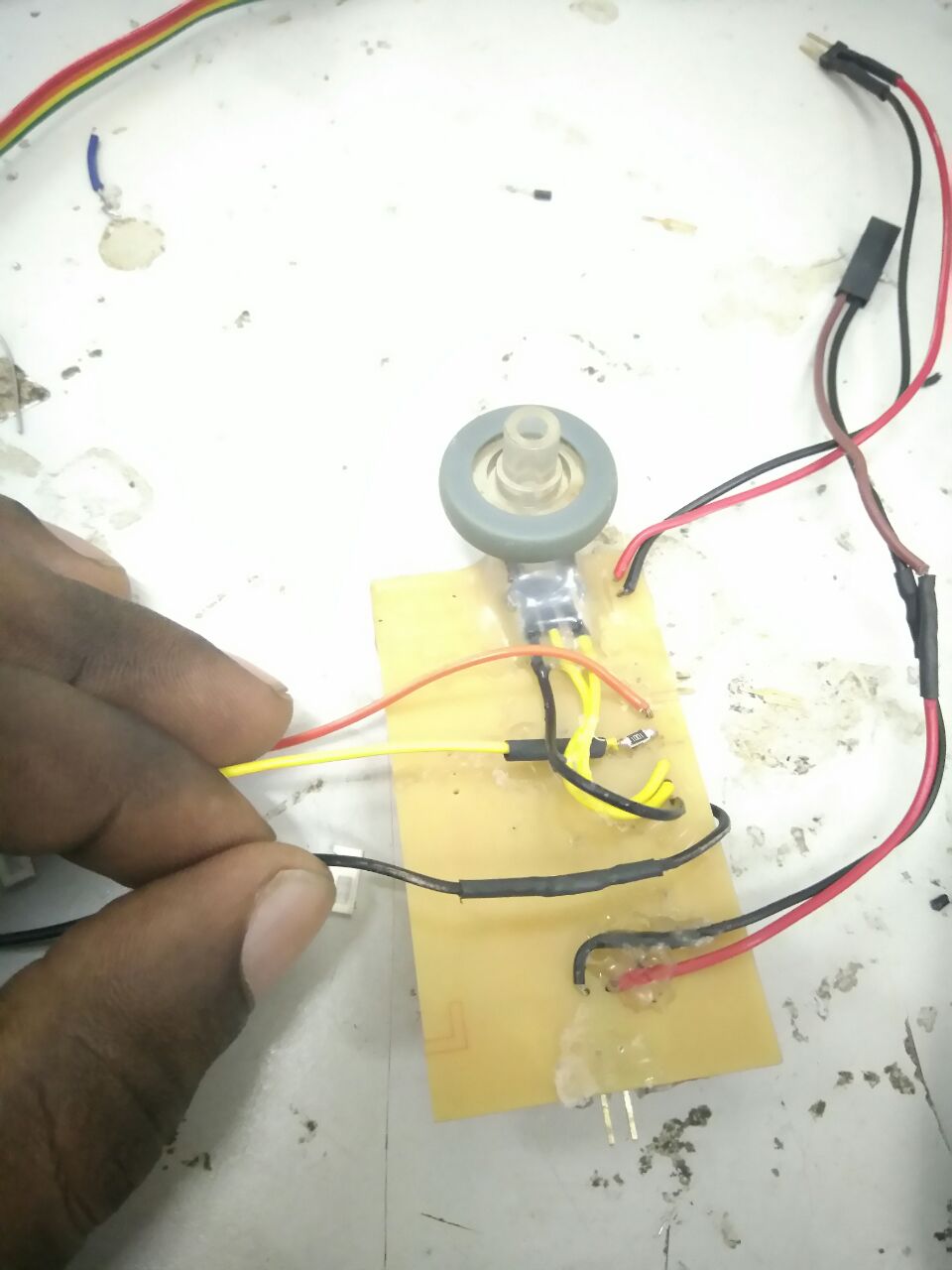
Well what do you know, it broke off just after soldering..!! I knew this would not be a lasting solution, so I remilled the board in addition to the bluetooth level shifter circuit.
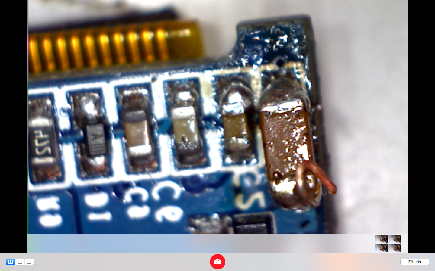
The setup till then when I tried soldering couple of smds,
During testing I accidently connected the OLED Vcc and GND to the alternate pins to the satsha board, thus buring the OLED. I was able to get it fixed temporarly since what actually burned off was a capacitor which I replaced with a 1uF. Later the whole trace came off.. I had a spare, so I continued with the new OLED
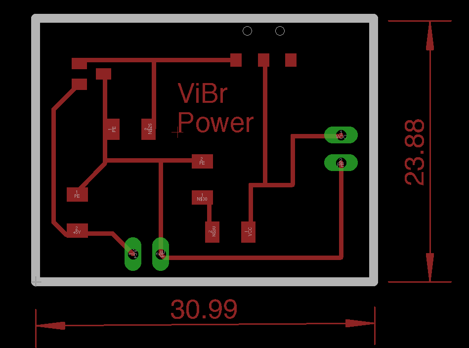
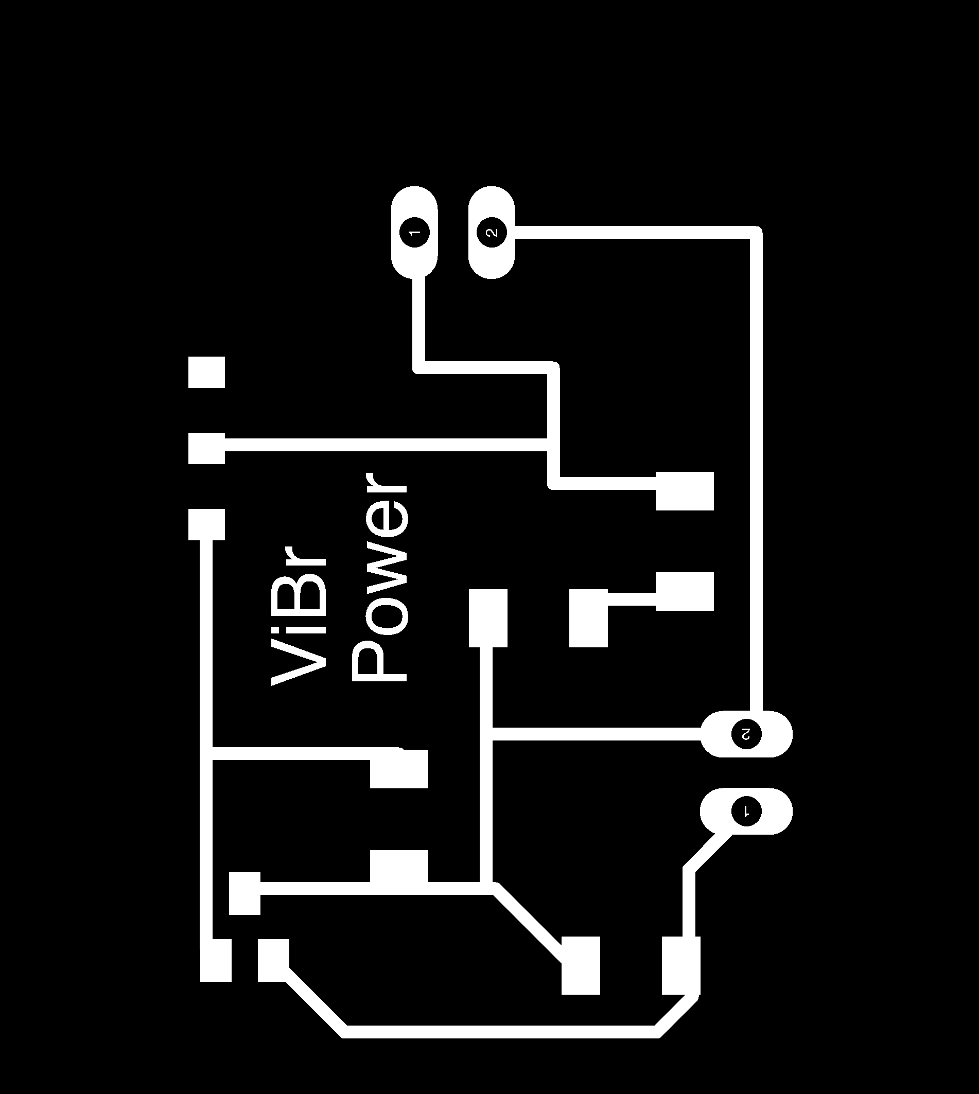
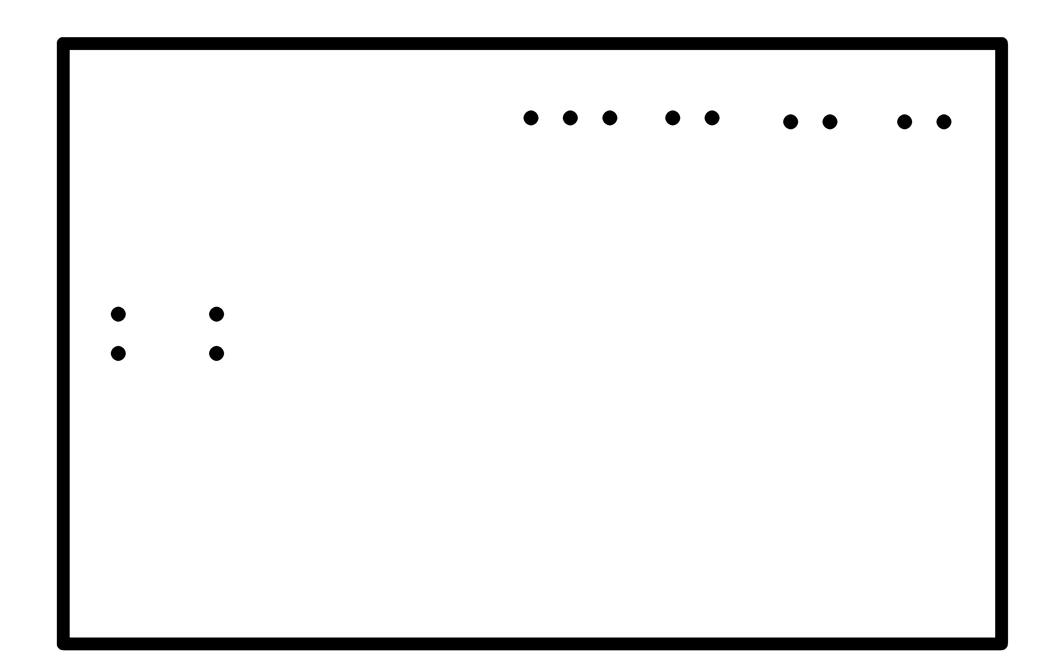
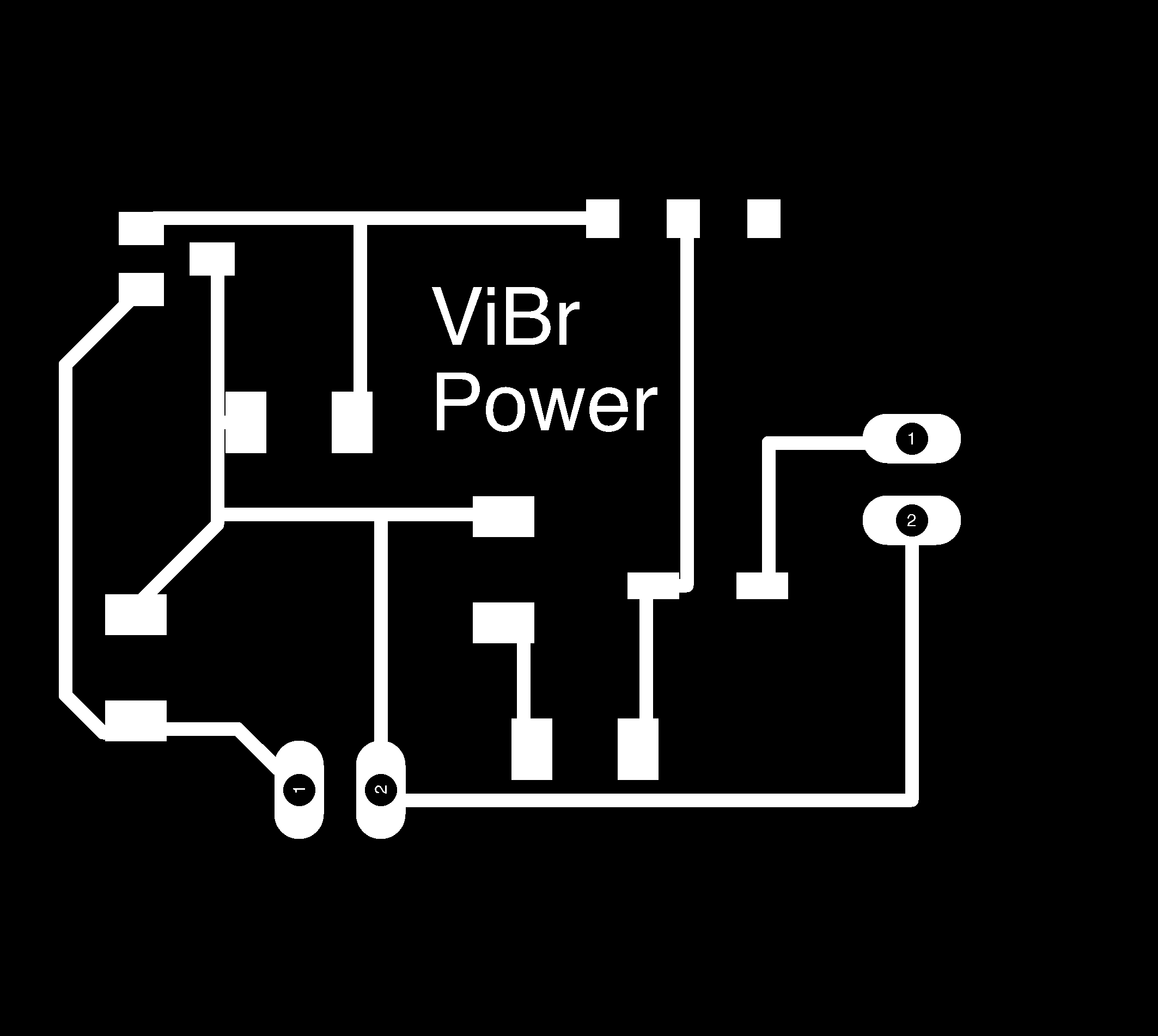
The power board schematic without the diode.
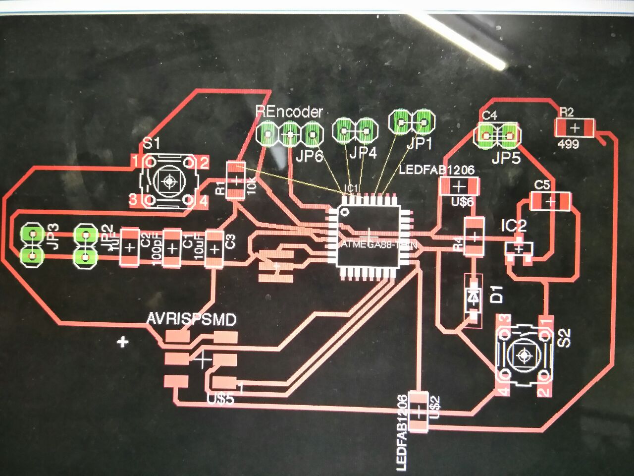
The power board design for the same.
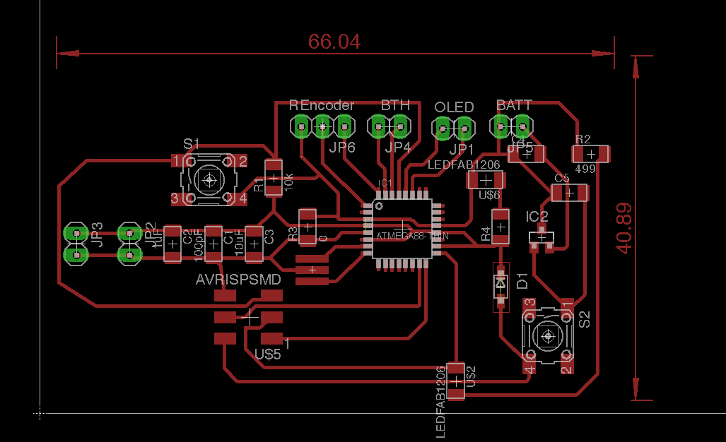
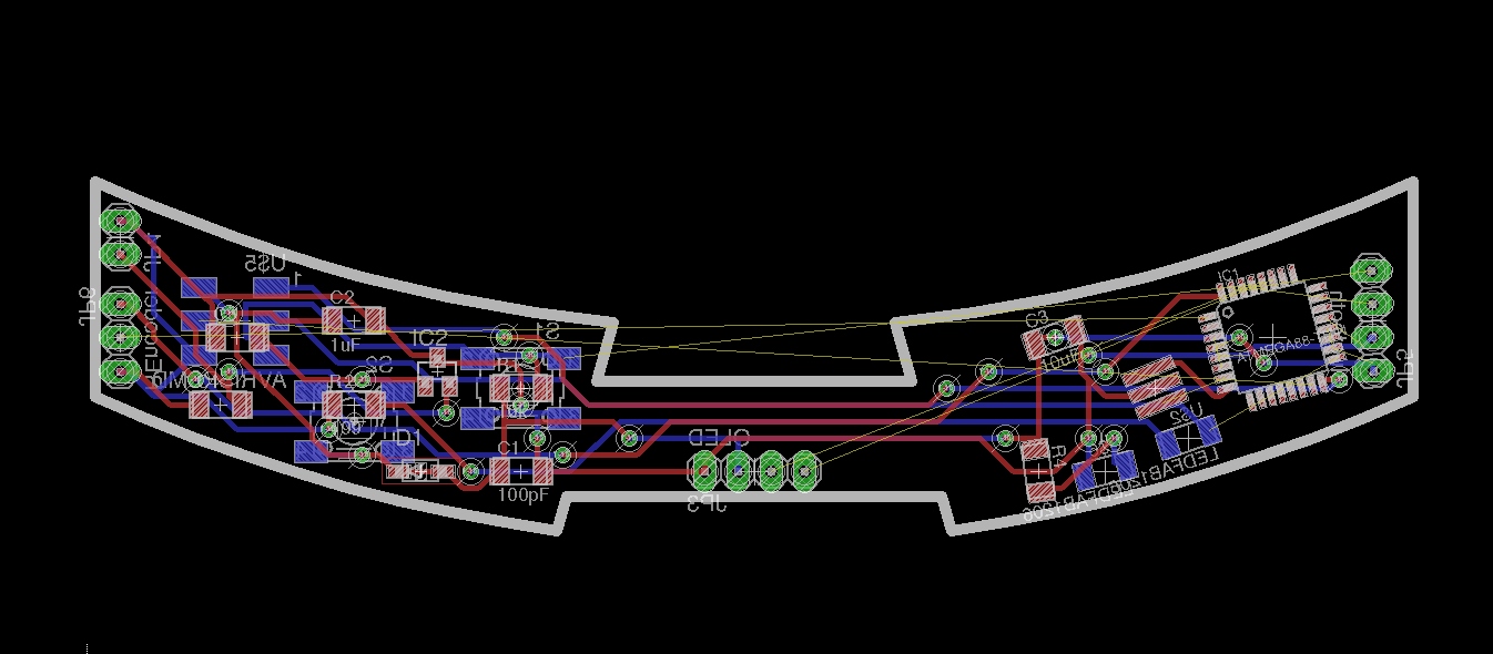
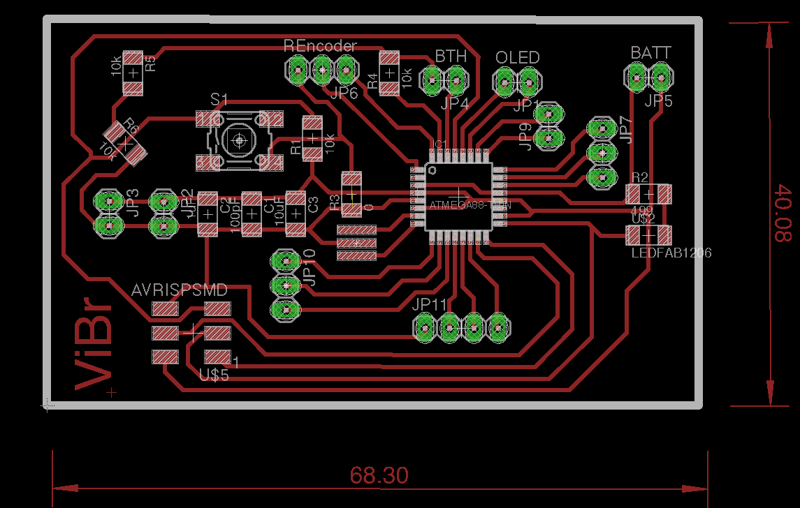
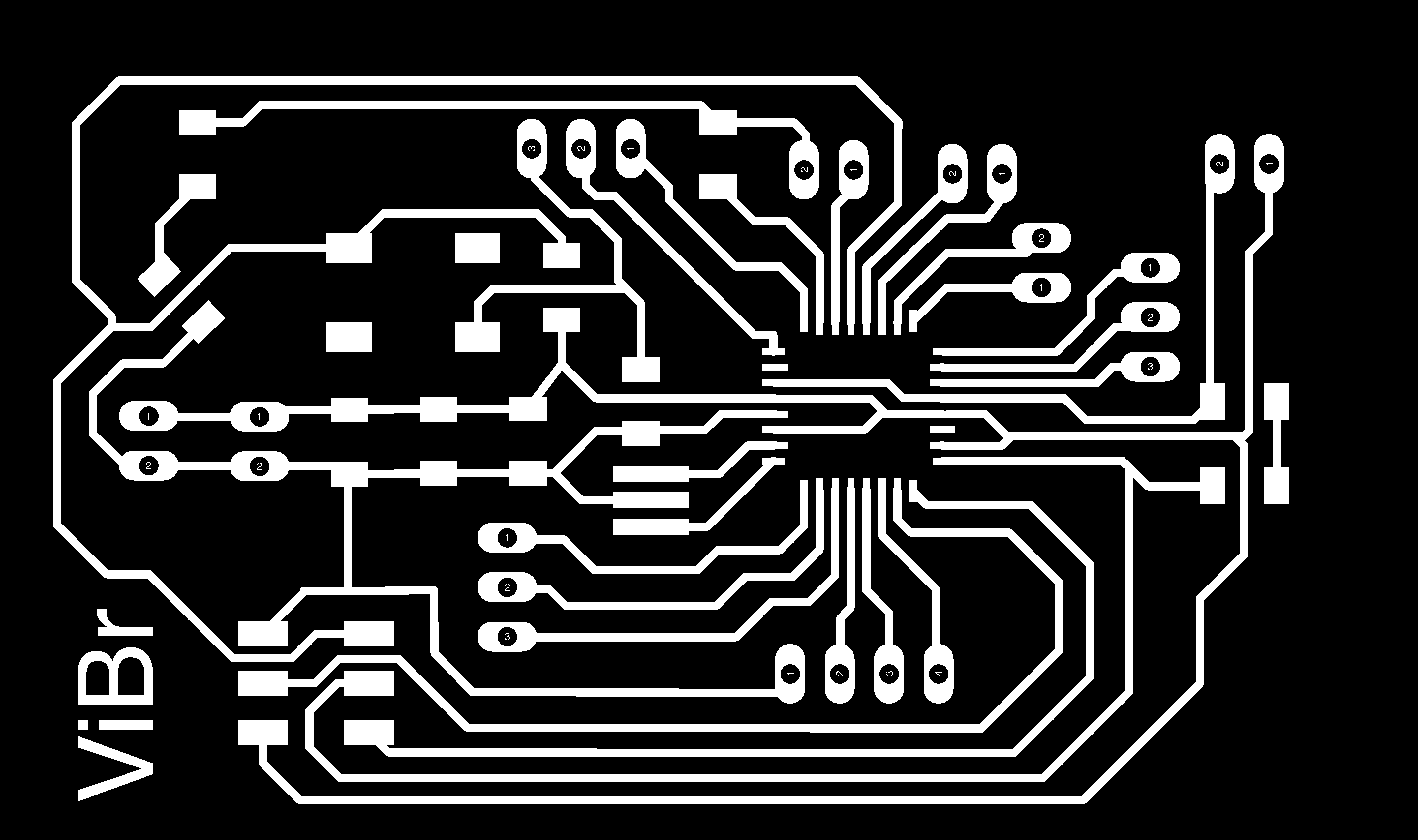
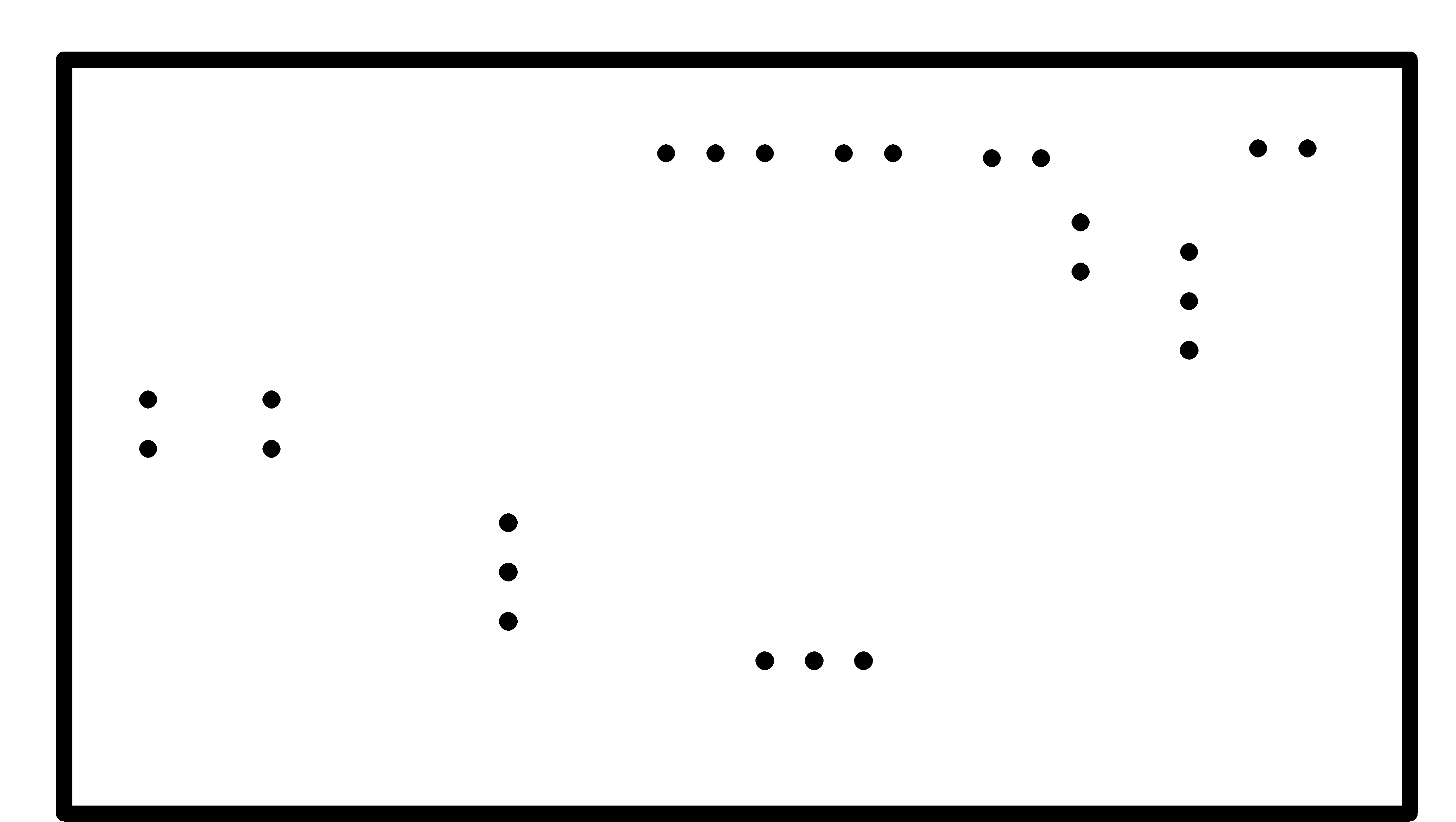
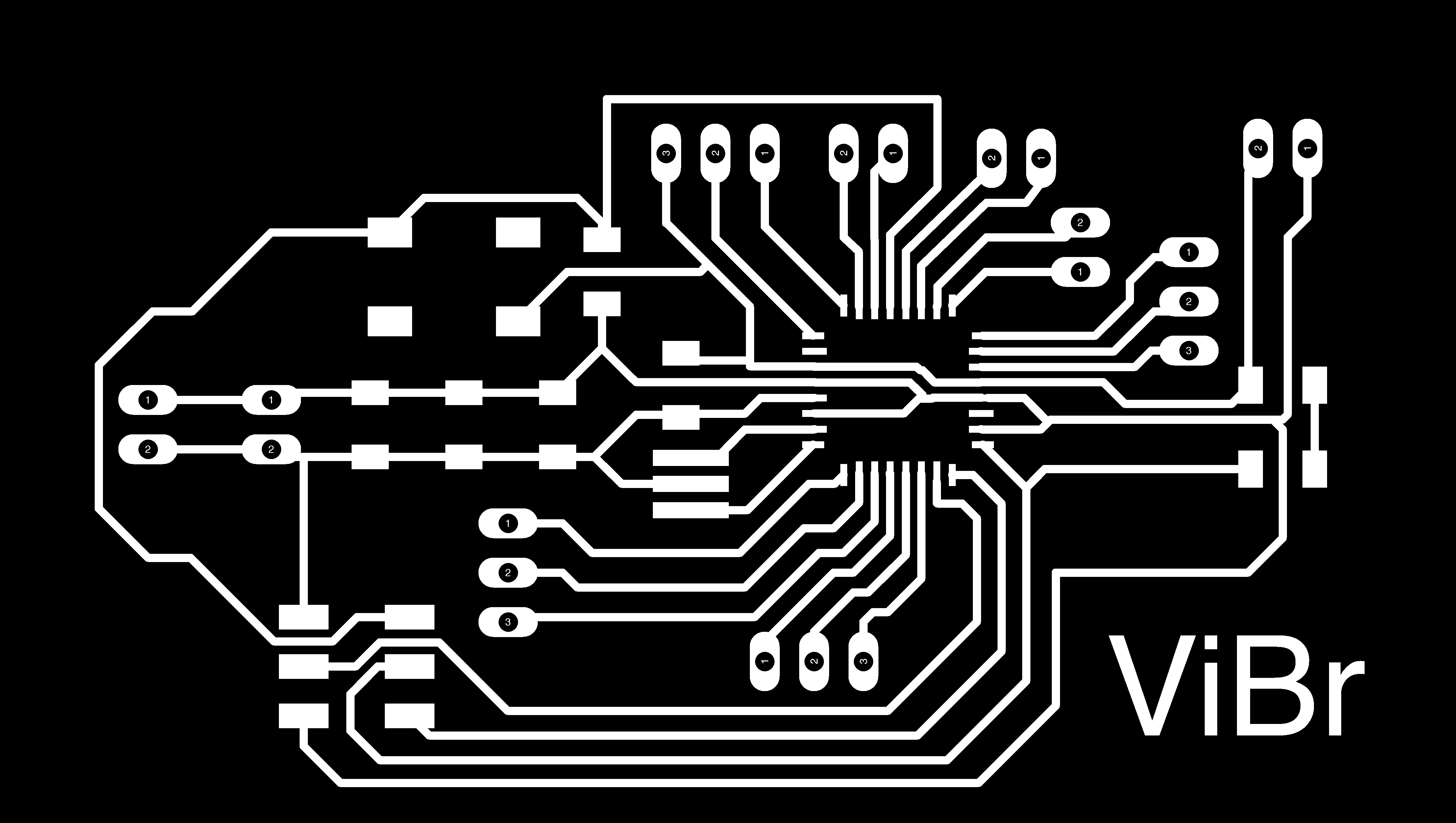
The atmega328p board I drew with the bluetooth level shifter circuit,
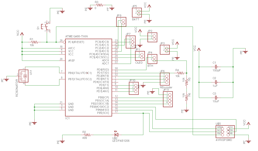
The board design for the same.
I also did a brake light circuit that I intend to cut with copper vinyl sheet which would be controlled by the accelerometer data available from the mobile and communicated via the bluetooth module.
The schematic for the mentioned circuit. This will be an add on to the project,
The board design for the same.
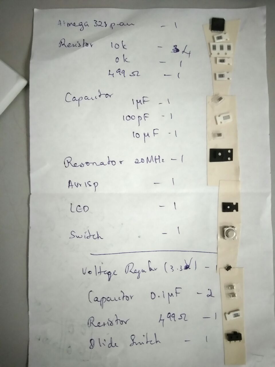
The components list, LED count may not be correct though..
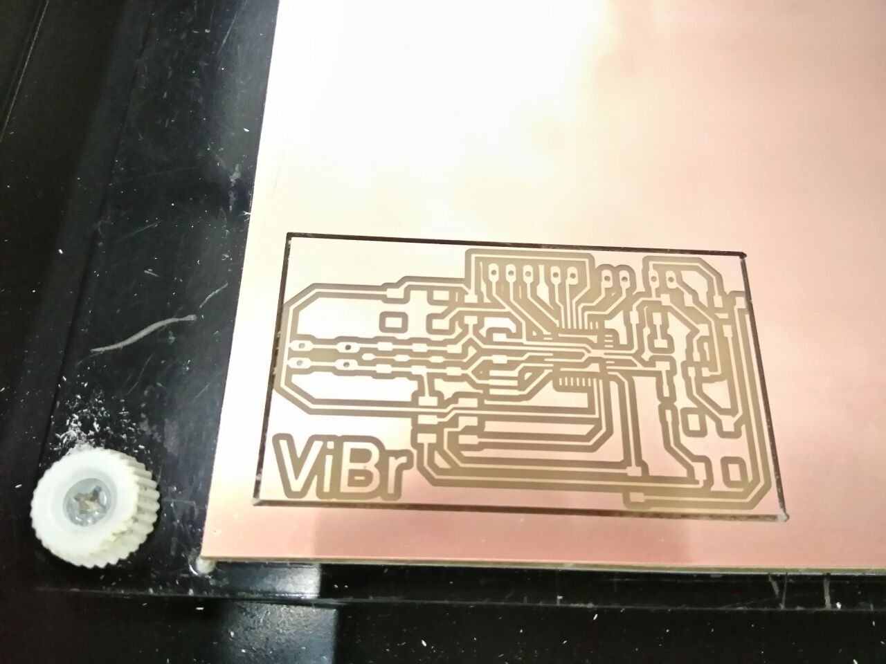
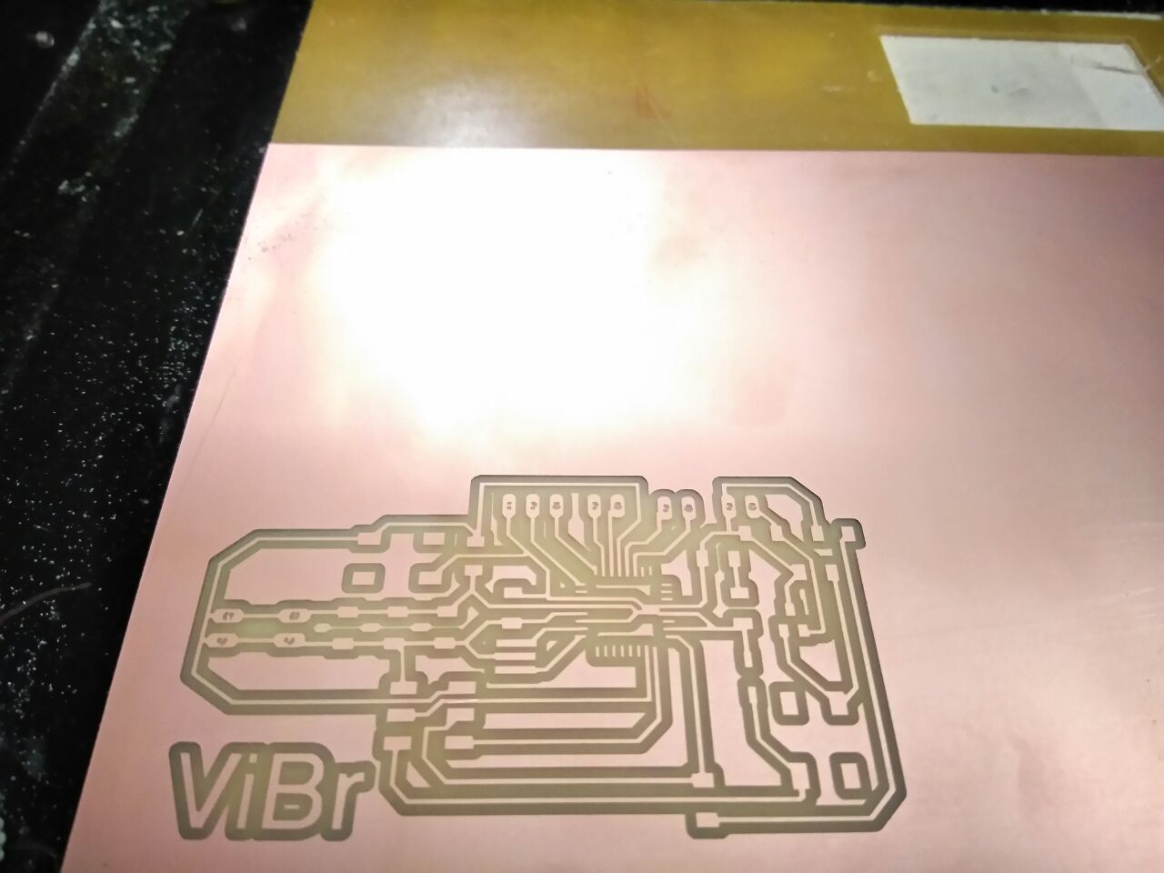
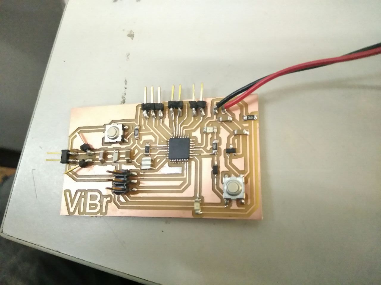
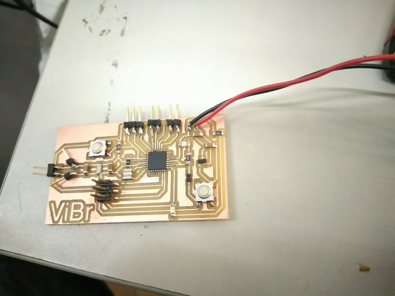
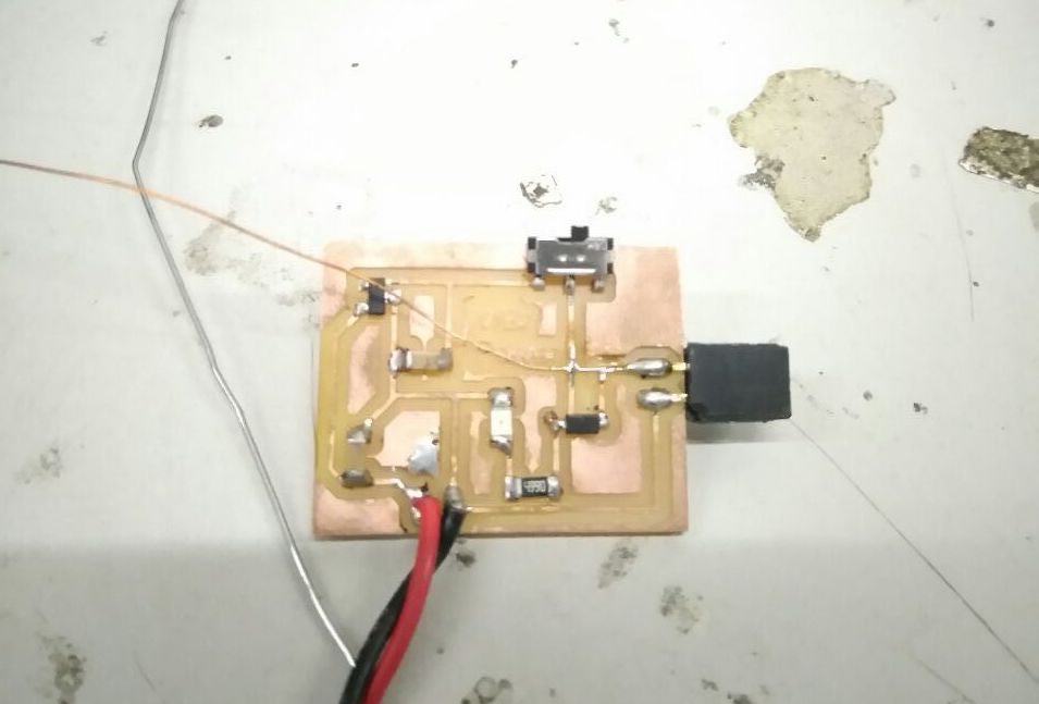
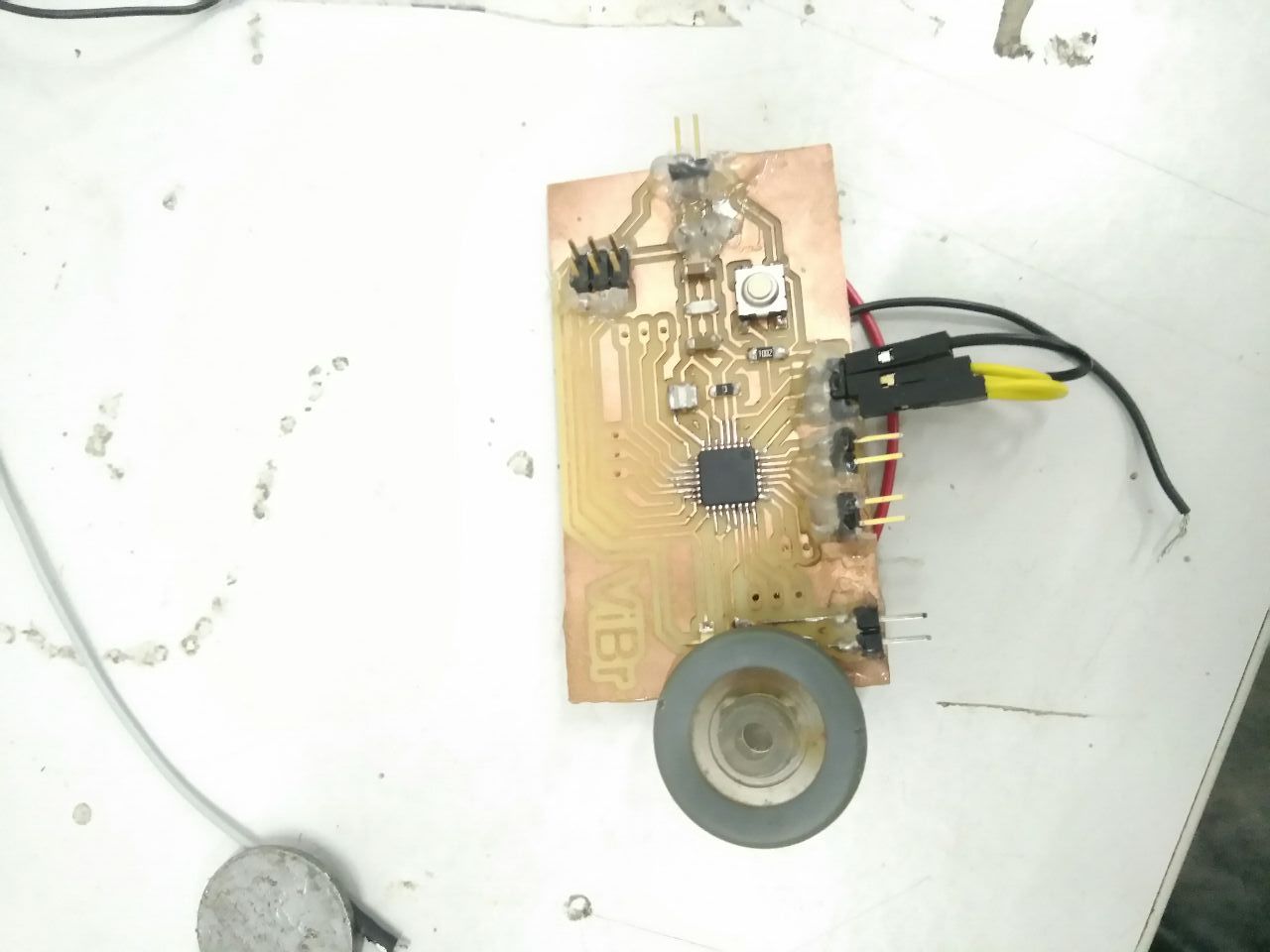
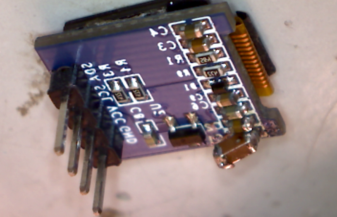
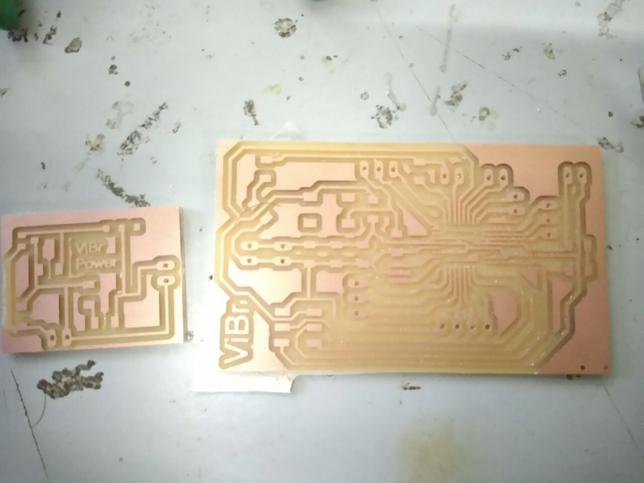
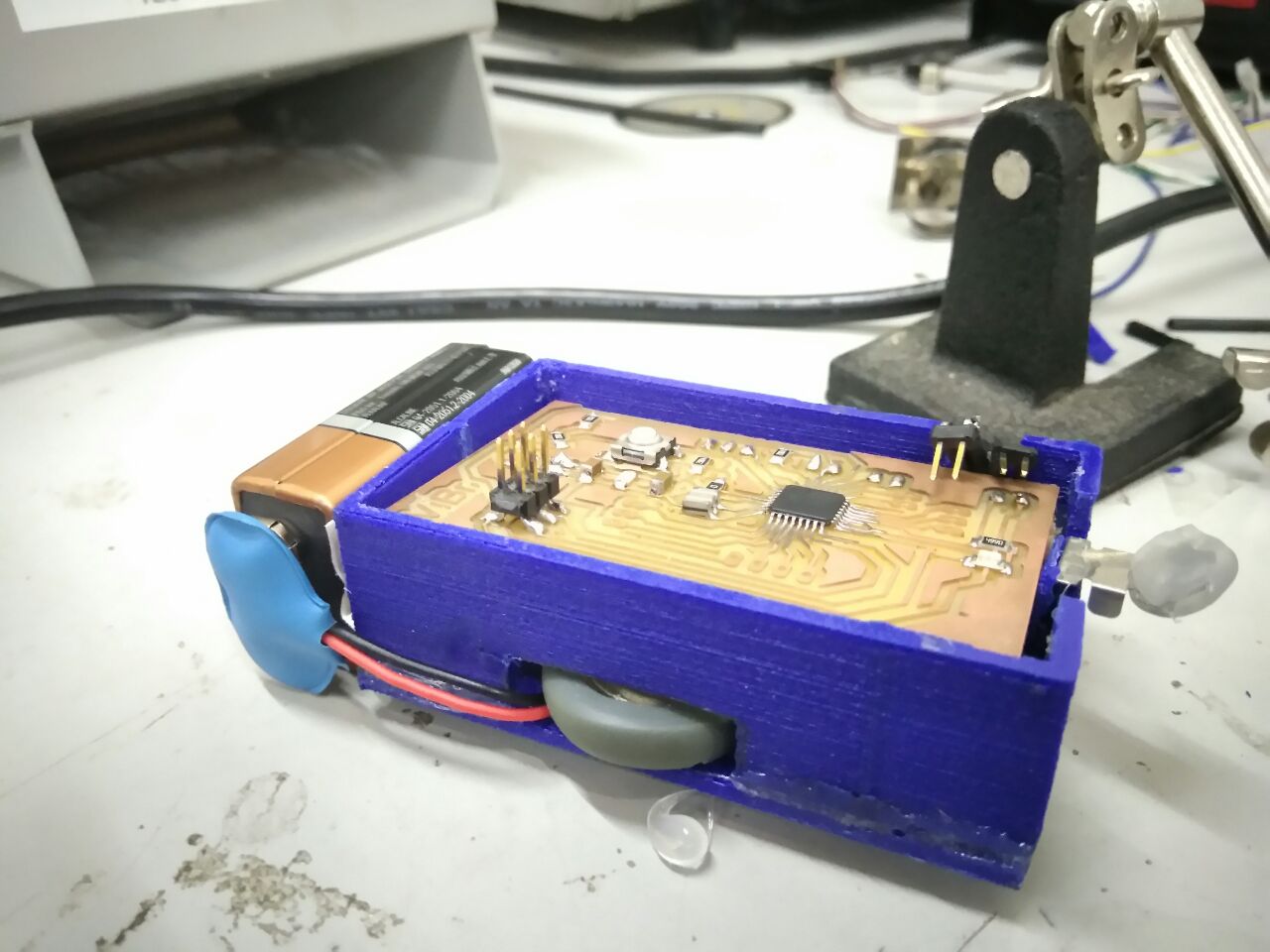
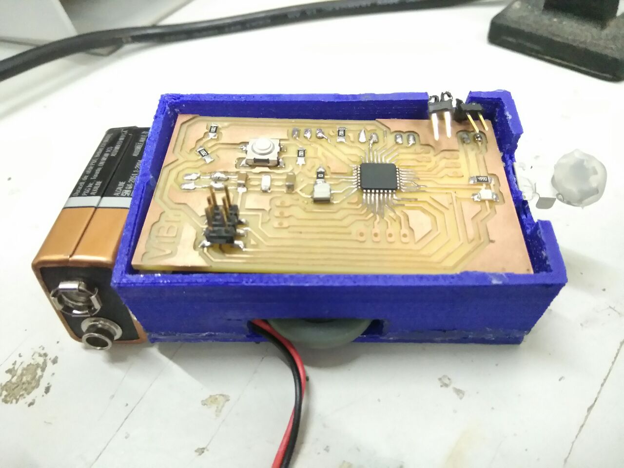
After milling the PCB with the above mentioned changes,
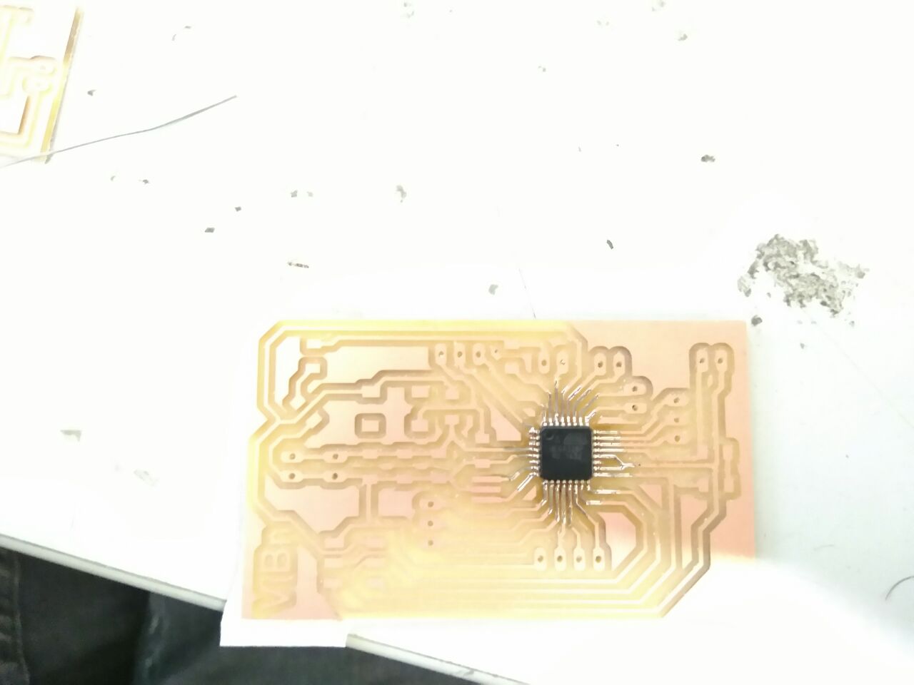
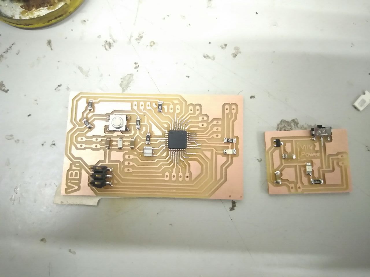
After soldering the components,
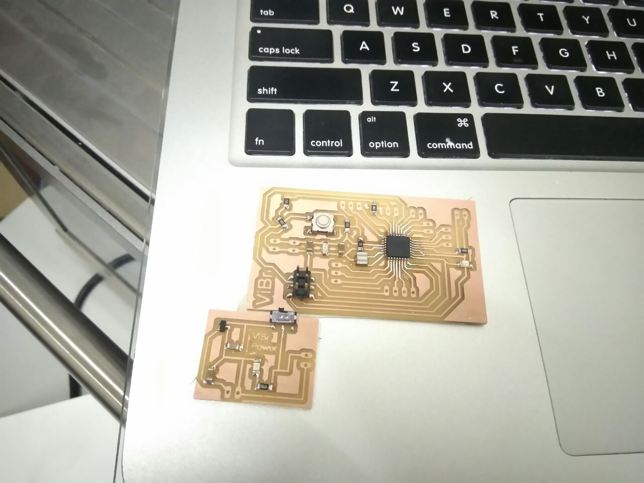
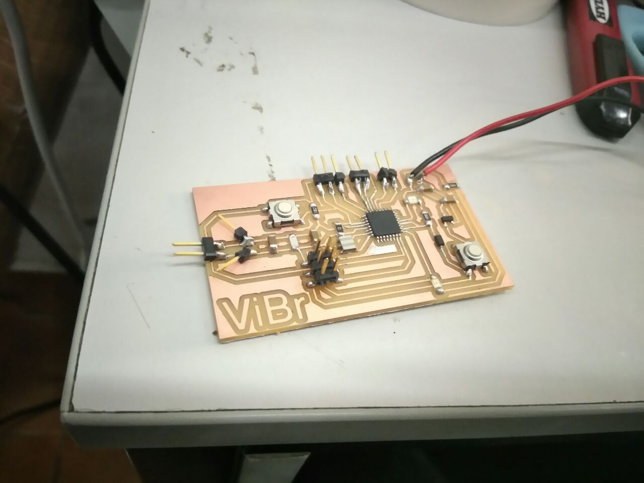
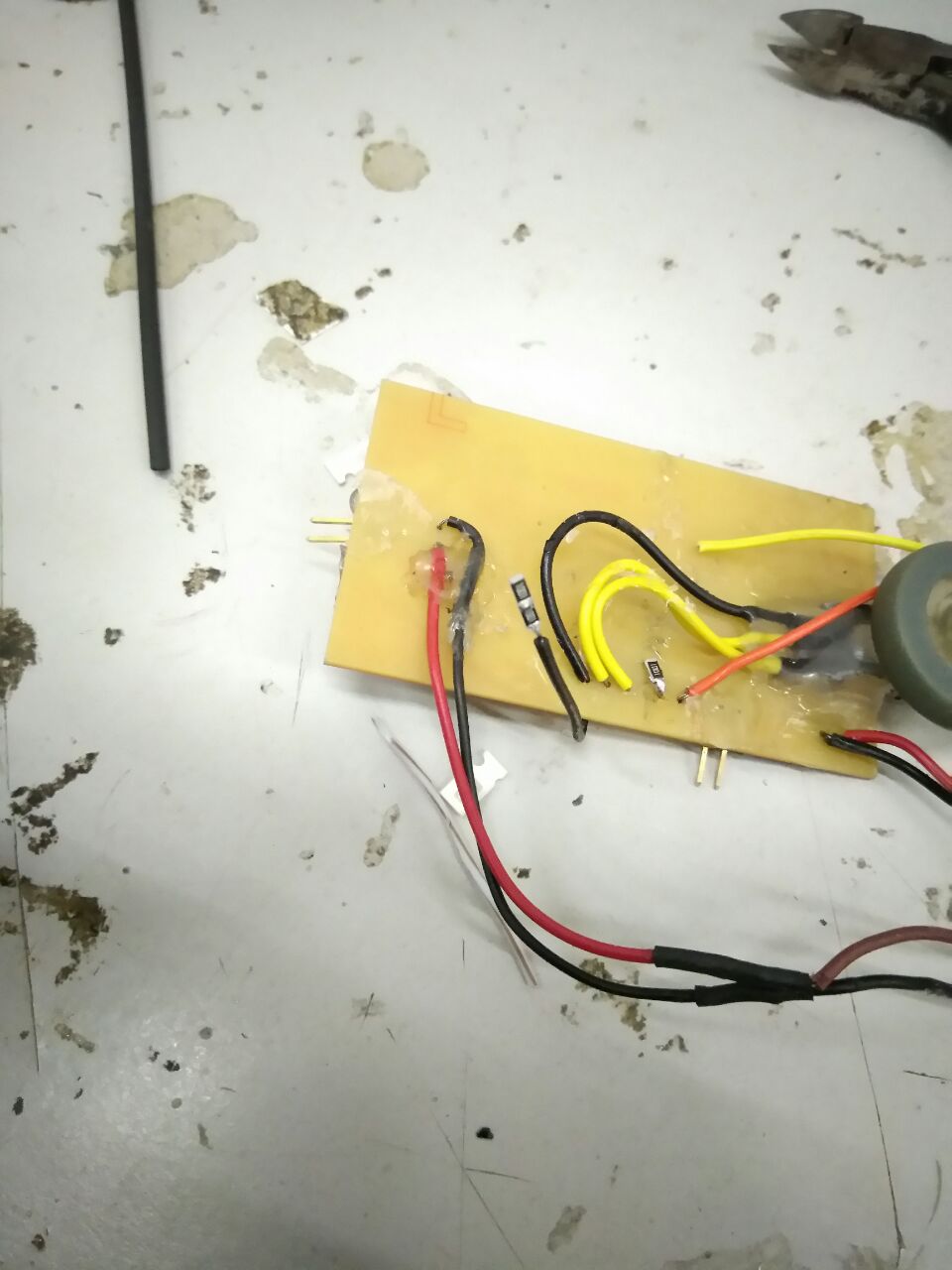
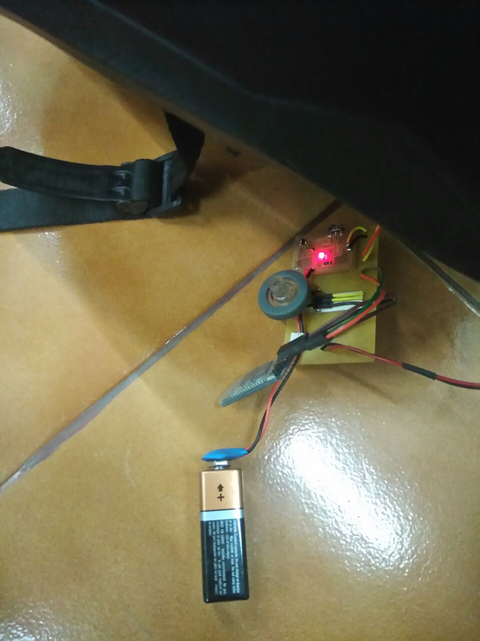
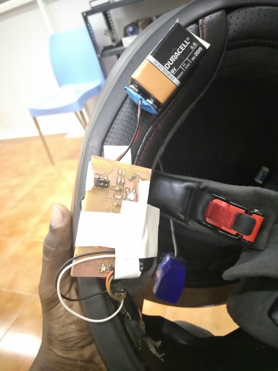
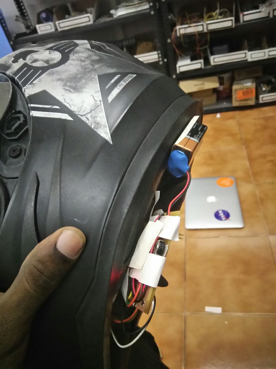
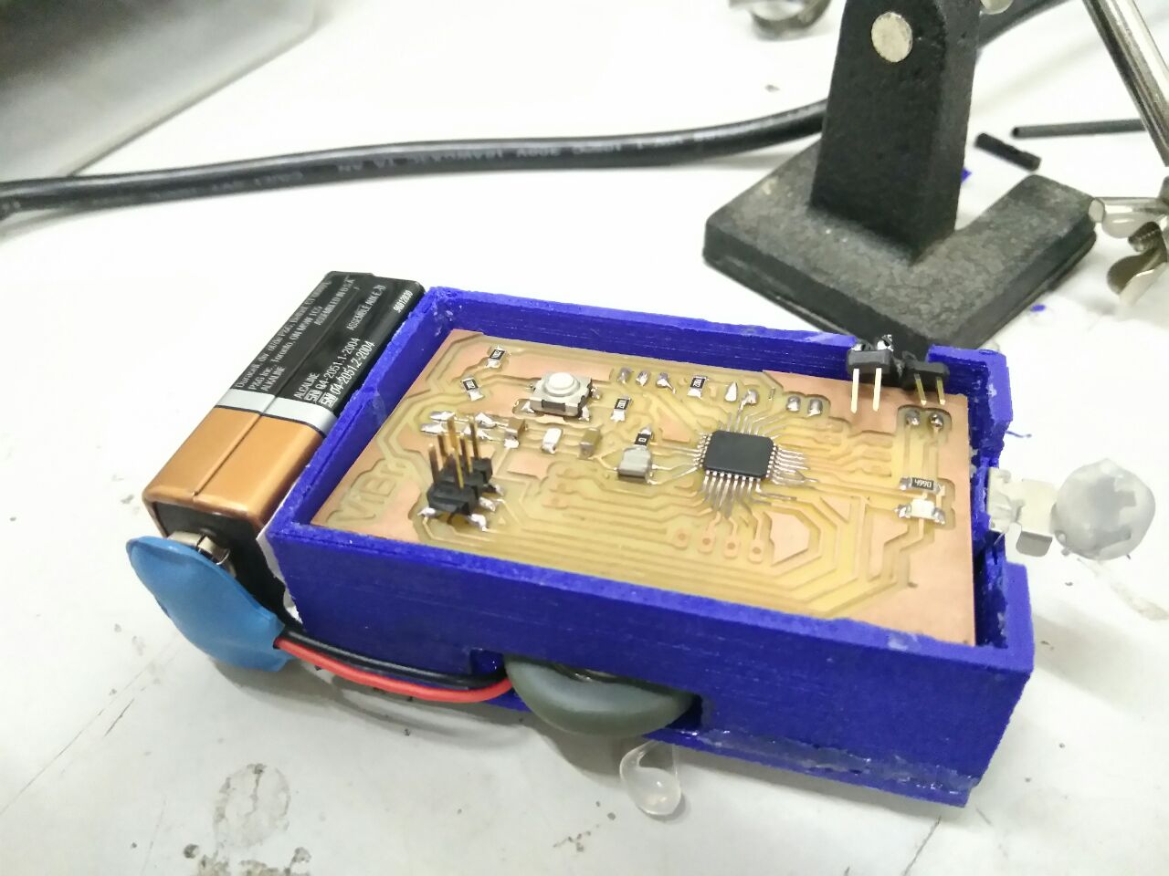
After organising all the external components and the extension wires,
Attaching everything onto the helmet to test,
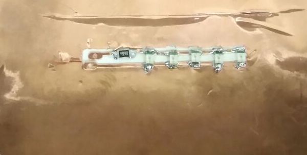
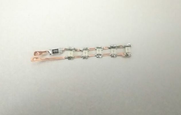
Vinyl Cutting a brake circuit
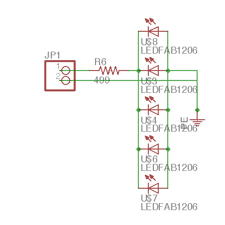
The schematic for the brakelight circuit I did,
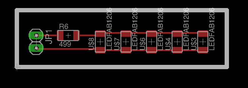
The board design for the same.
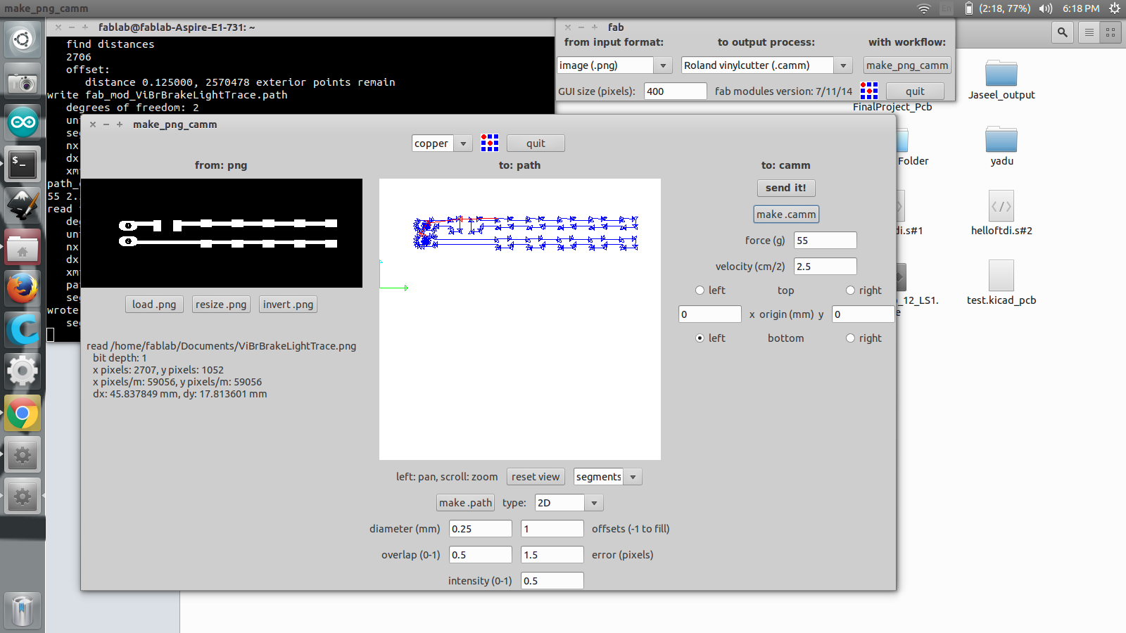
I used the Roland VinylCutter to cut the circuit. Following is a screenshot I took when using the Fab Modules
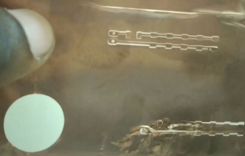
After doing a test cut, I redid circuit again.
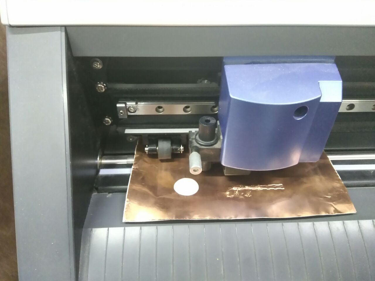
I spend sometime unable to figure out why the machine was not running, but later found out that it was due to the origin I set. The cutting head was origined to the opposite edge.
Soldering the components was a bit difficult because the trace would come or move off from its position.
I did not get time to connect this circuit to the satsha board and program it, but will definitely do it.
Final Touches for the Final Project
Since everything work like its supposed to, I tried 3D printing a case for the electronics and the rotary encoder,
But half way through printing it, the alignment of the print head changed and the extruder got clogged. I had to stop the print. But since my other collegues wanted to use the 3D printer, I decided not to print it again at that moment.
I was able to savage from what I got printer and made it work.
Also I used an smd slider switch, it was so small to use that I created a extension to the toggle switch header from some spare part of something..!!
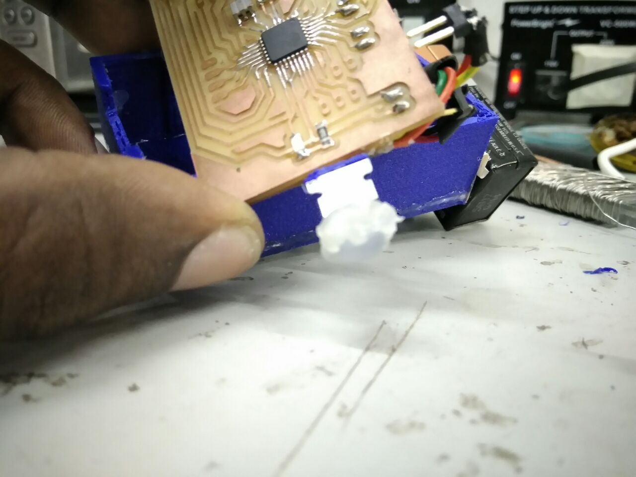
Since hot glue was running everywhere it wasn't cool enough.
I got some thin foam sheets, and slightly cut it to its dimension so that I can bend it nicely as one single piece,
The final product,
Download files
Do ignore the file names, I added all the files I used, some designs I did not even save, so these are what I did save.
During my documentation, I did mention I only had end files to schematics and board designs, you may get some idea on what I was talking about from those .png files I used for milling.
Documenting one's project in a single sitting is not adviced..!!
ViBrPrism.3dm
ViBrMirrorLaser.dxf
ViBrChamber.stl
ViBrChamber2.stl
ViBrElectronicsChamber.stl
ViBrOpticsChamber.stl
ViBrChamber.3dm
ViBrChamber2.3dm
ViBrChamber3.3dm
ViBrStorage.3dm
ViBrCircuitLayout.dxf
ViBrReflector.3dm
ViBr.sch
ViBr.brd
ViBrBrakeLight.sch
ViBrBrakeLight.brd
ViBrBrakeLightTrace.png
ViBrPower.sch
ViBrPower.brd
GhostEyeCut.png
GhostEyePowerCut.png
GhostEyePowerTrace.png
GhostEyeTrace.png
ViBrCut.png
ViBrCut2.png
ViBrPowerTrace.png
ViBrTrace.png
ViBrTrace2.png
ViBr.aia
License

This work is licensed under a Creative Commons Attribution-NonCommercial-ShareAlike 4.0 International License.