Computer-Aided Design

2D Modeling - Raster and Vector Tools

A raster image is made of up pixels, each a different color, arranged to display an image.

A vector image is made up of paths, each with a mathematical formula (vector) that tells the path how it is shaped and what color it is bordered with or filled by.

For a layman to understand, if you can zoom in on an image and it get pixalated at the edges, then it is a raster image. But if an image has fine lines even after zooming into it, then it is a vector image.

The following image gives a good idea of what the major difference is.


Photoshop - 2D Raster

Photoshop is a Image Editor provided by Adobe. I used Photoshop to create a raster image of my project. It is a crude design. Following is some of the screenshots I took while creating the design.


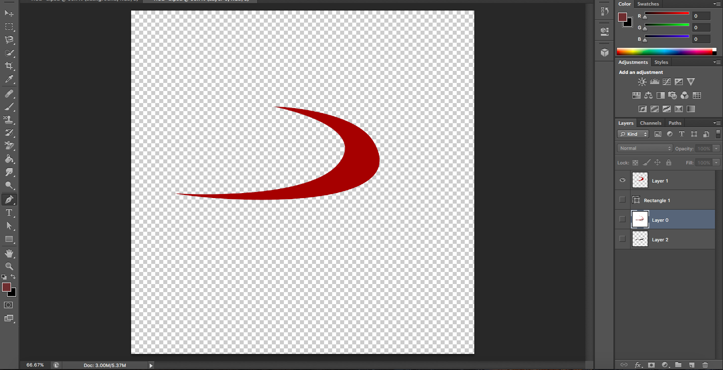
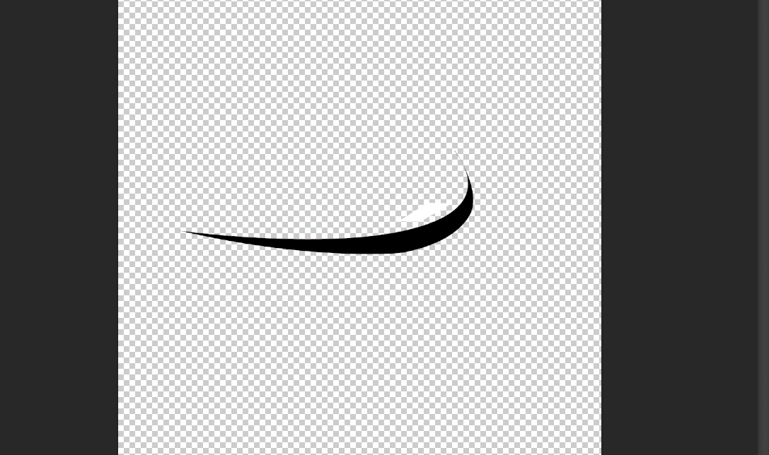
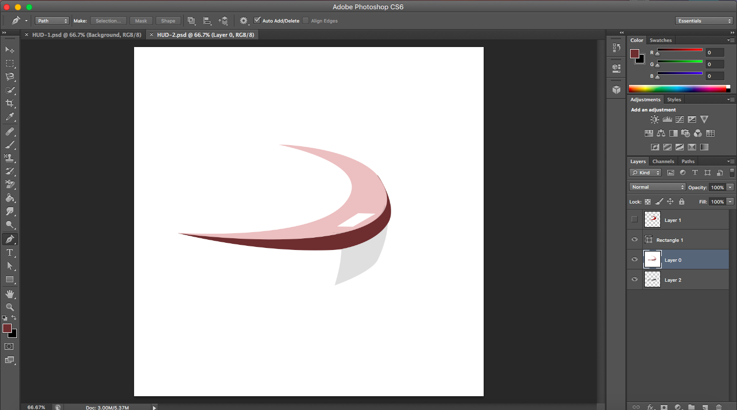
I mainly used only the pen tool for creating this. Following are some basic intro to short hands and some of the things I learned.
Cmd + Backspace -> Fill selected space with foreground color.
Cmd + D -> Remove selection
Alt + click + drag -> To deselect parts that got selected.
[ and ] -> To increase and decrease pointer size.
Clone tool -> Alt + Click to clone patterns
Art brush -> Selects color.
Gradient tool -> Based on layer and can be used to apply different gradients to colour.

Lasso tool -> Free hand selection tool.
Magnetic Lasso tool -> Selects based on color boundary along with freehand selection.
Magic tool -> Auto selection based on color boundary.
These selection tools have tolerance that can be adjusted depending upon the need.

A copy of my photoshop work is available as photoshopwork

GIMP - 2D Raster

GIMP is an open source Image Editor. I used GIMP to have comparison with Photoshop. I did not get to use most of the tools in GIMP, and did not quite get a lot of short cuts ( x -> Lets you toggle foreground color and background color). I tried out one of the tutorials provided in GIMP. Following is a gif of my screenshots


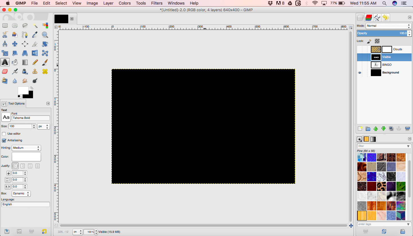
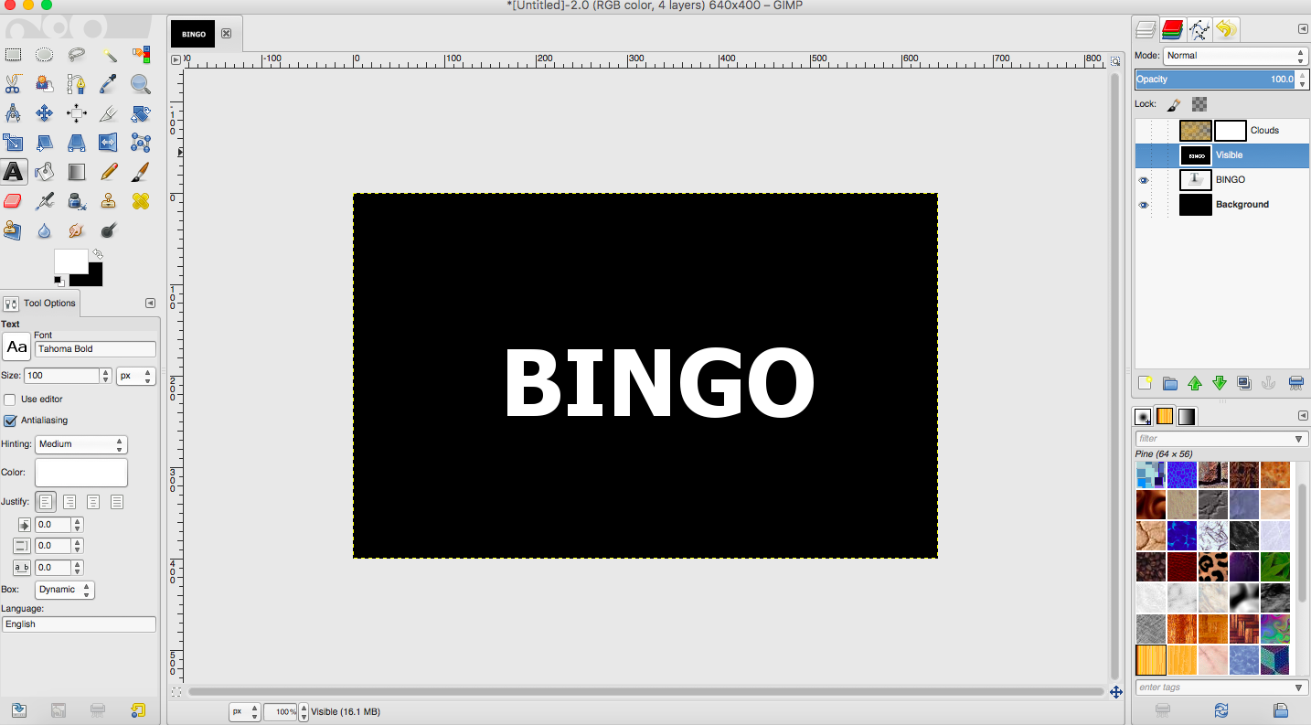
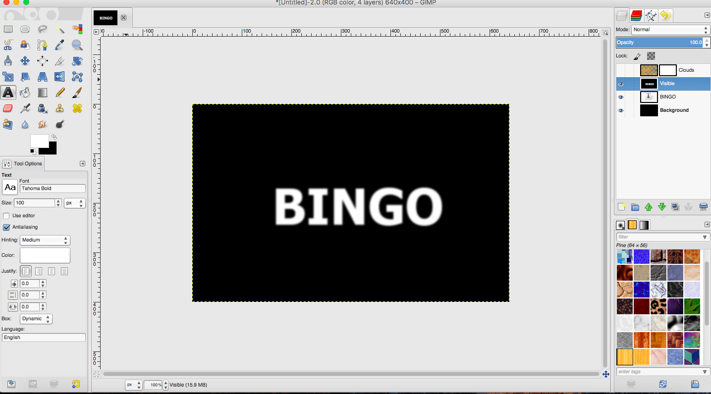
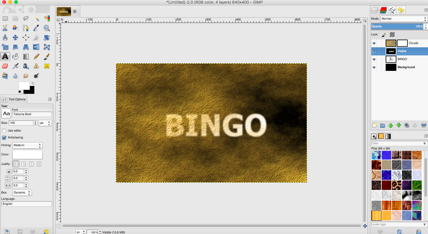
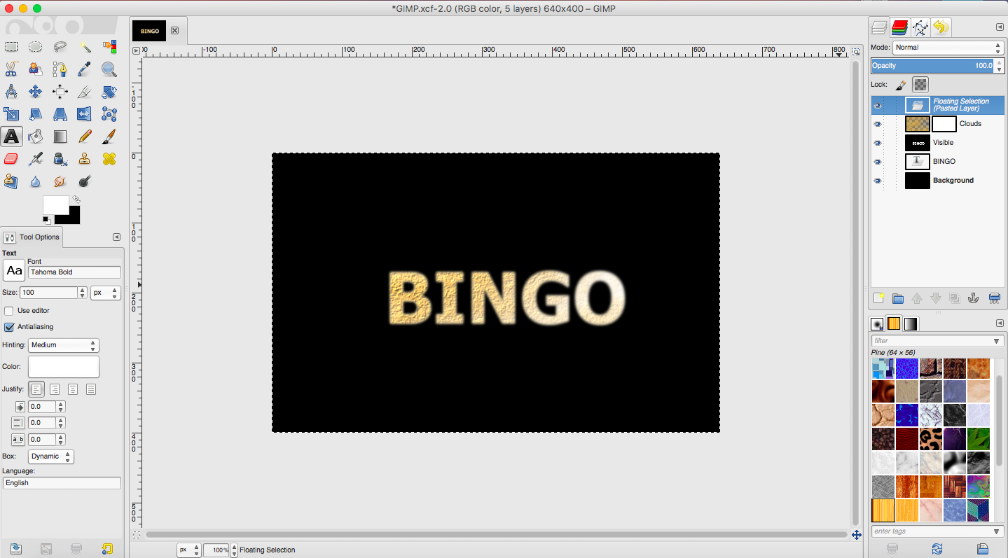
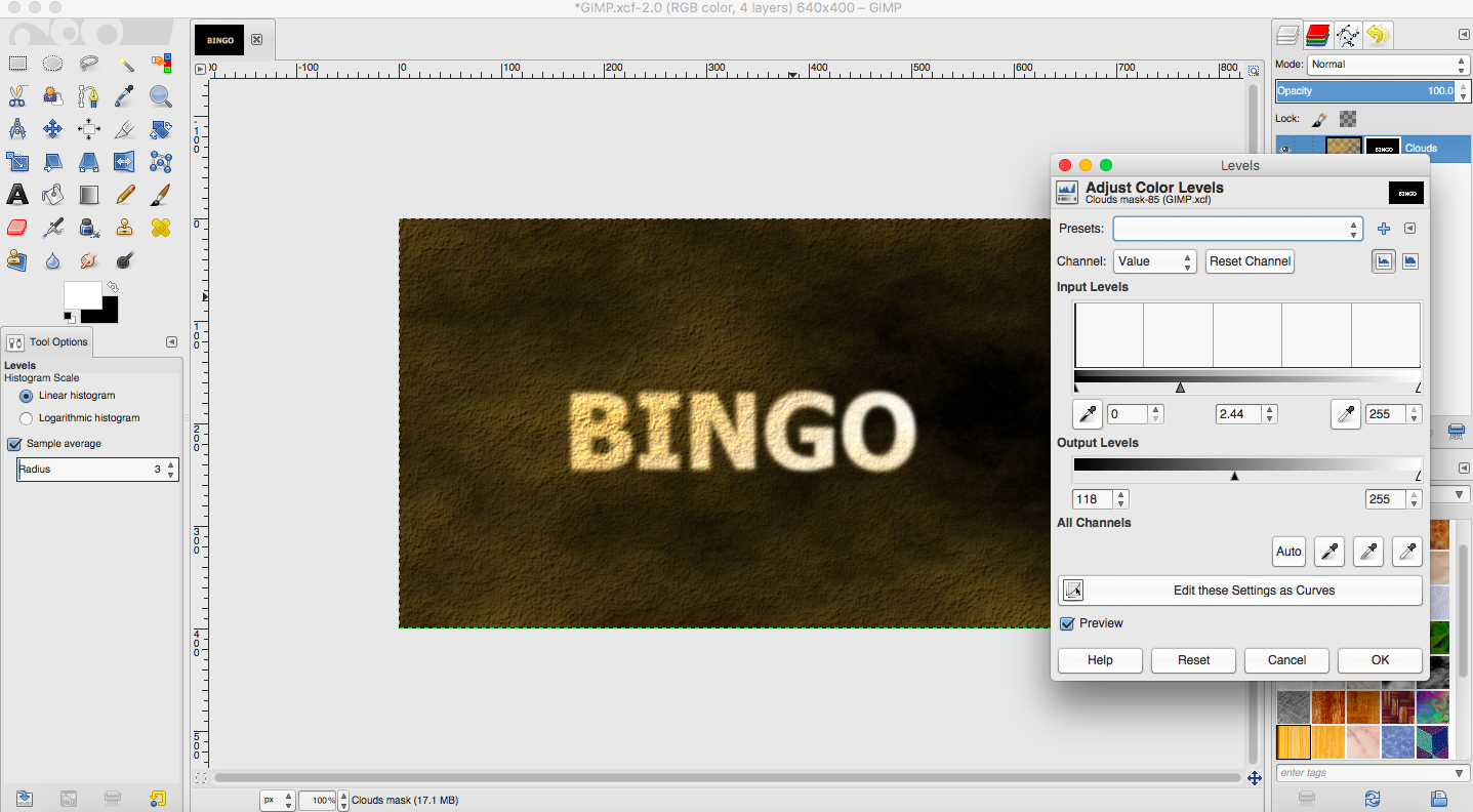
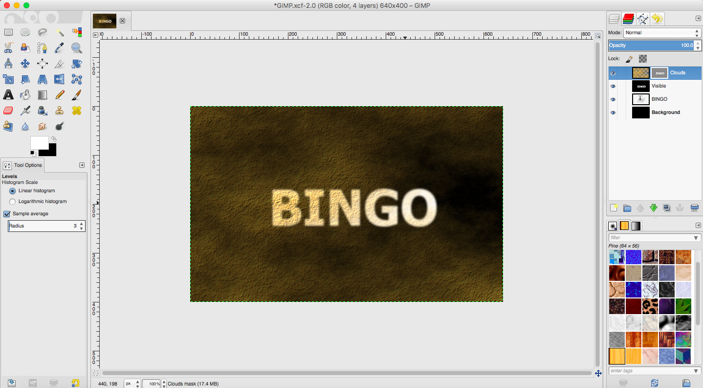
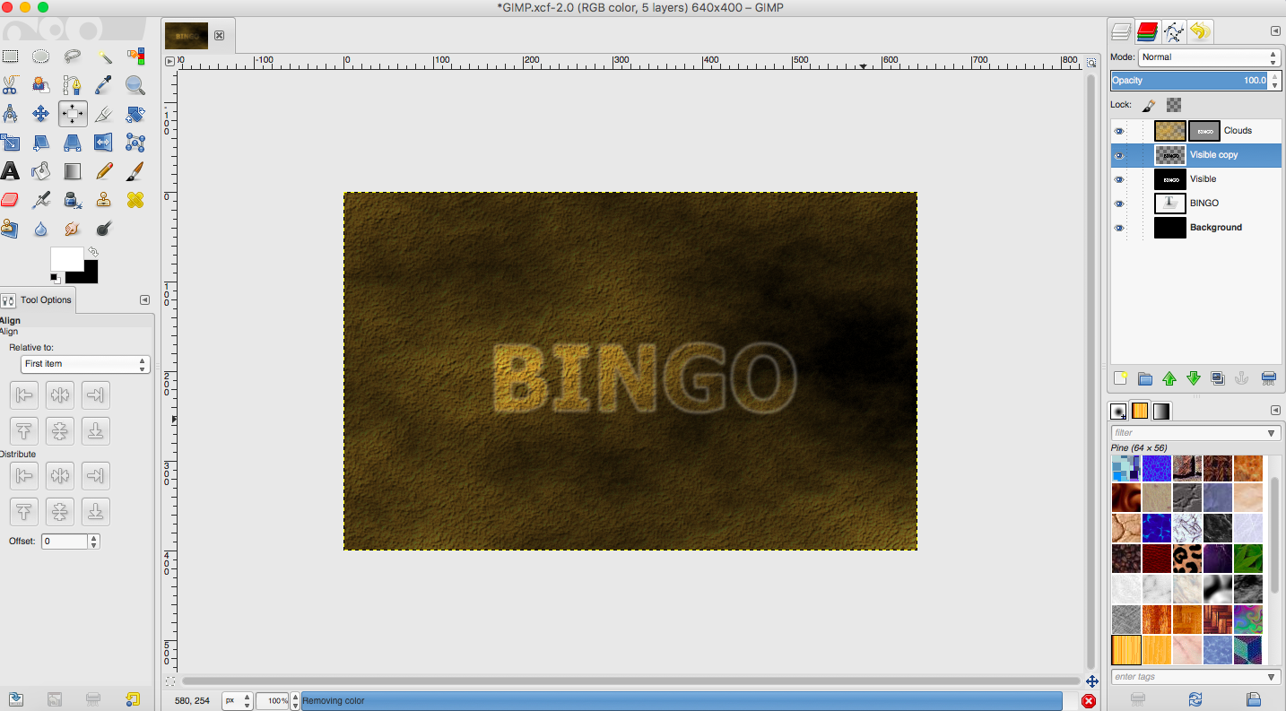
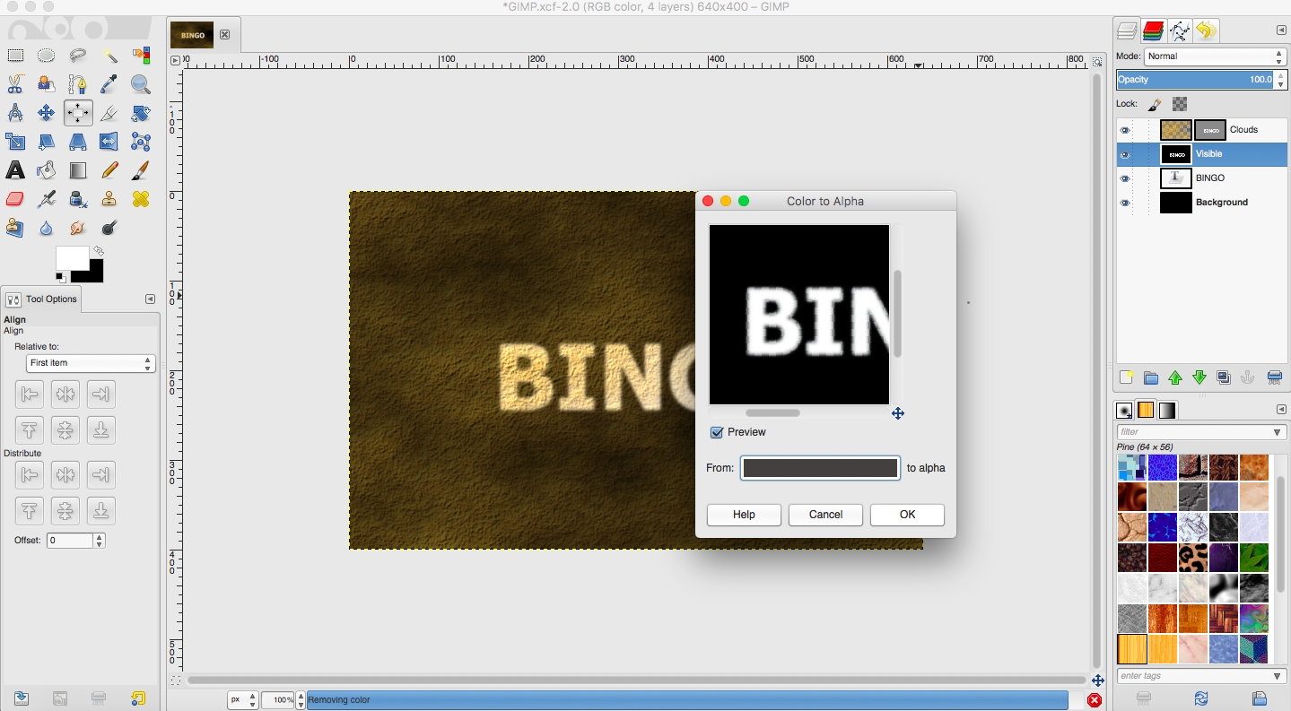
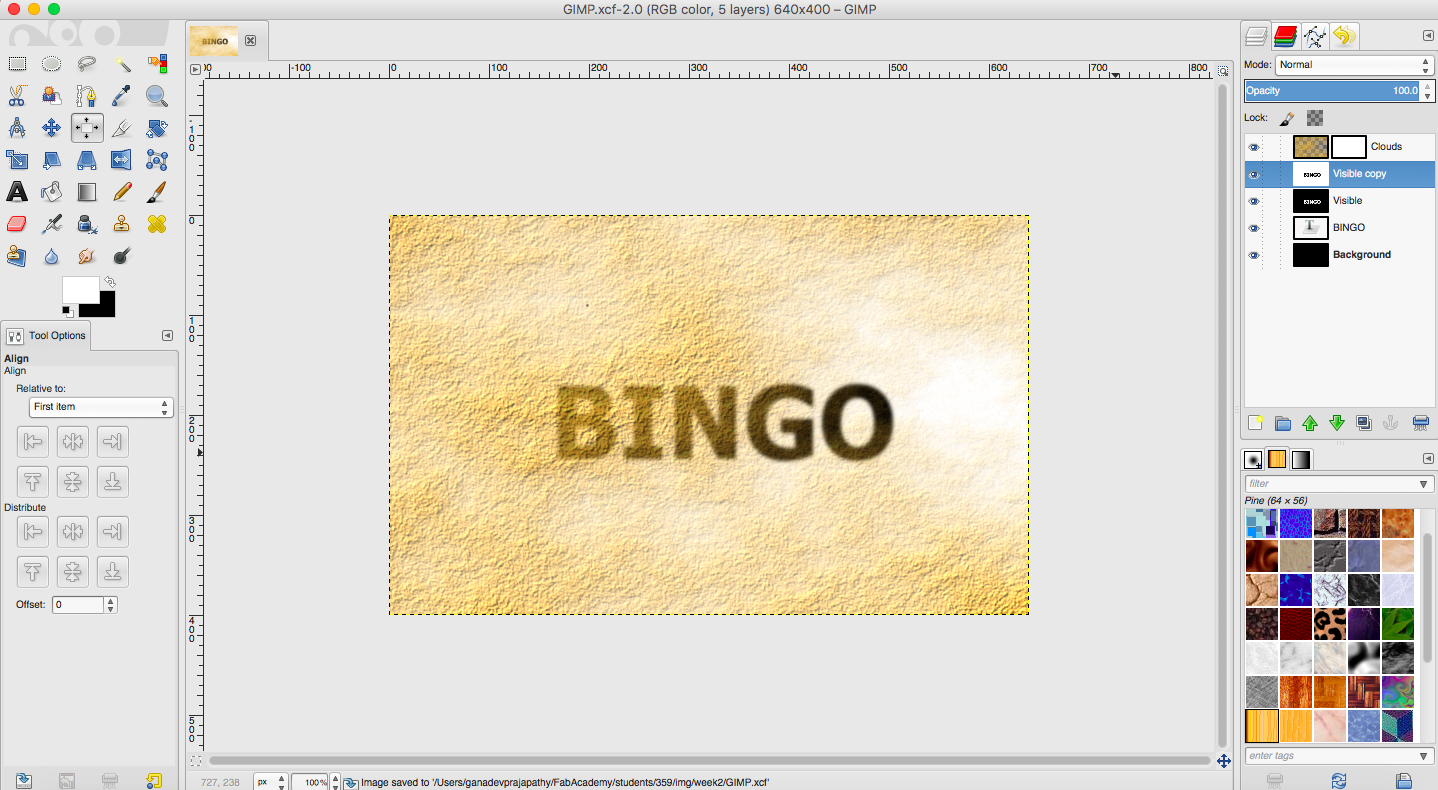
A copy of my GIMP work is available as Bingo.xcf

My Evaluation

I feel more comfortable using Photoshop than GIMP. The tools that I need were much more easier to get to. GIMP even though it looks easy, I couldnt start of without hitting the tutorials.

Inkscape - 2D Vector

Inkscape is an open-source vector graphics editor which uses Scalable Vector Graphics (SVG), an open XML-based W3C standard, as the native format. Its a pretty straight forward and intuitive tool.

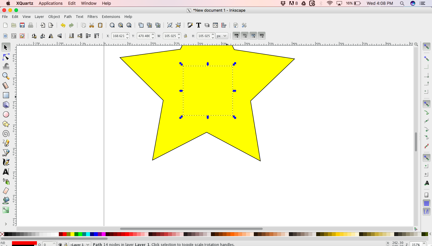
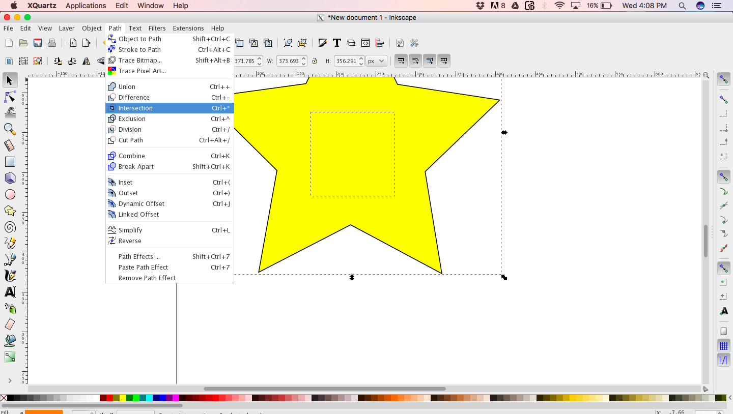
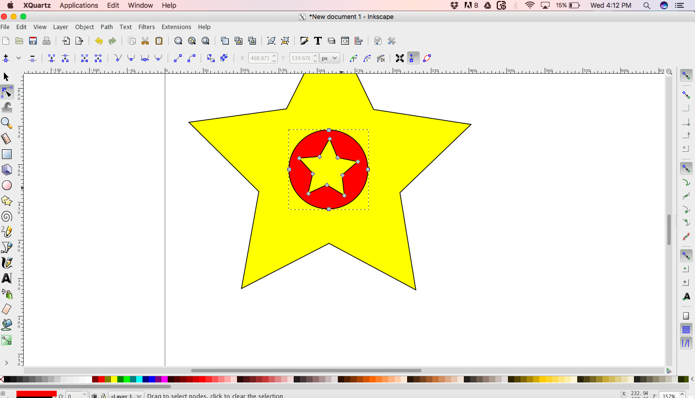
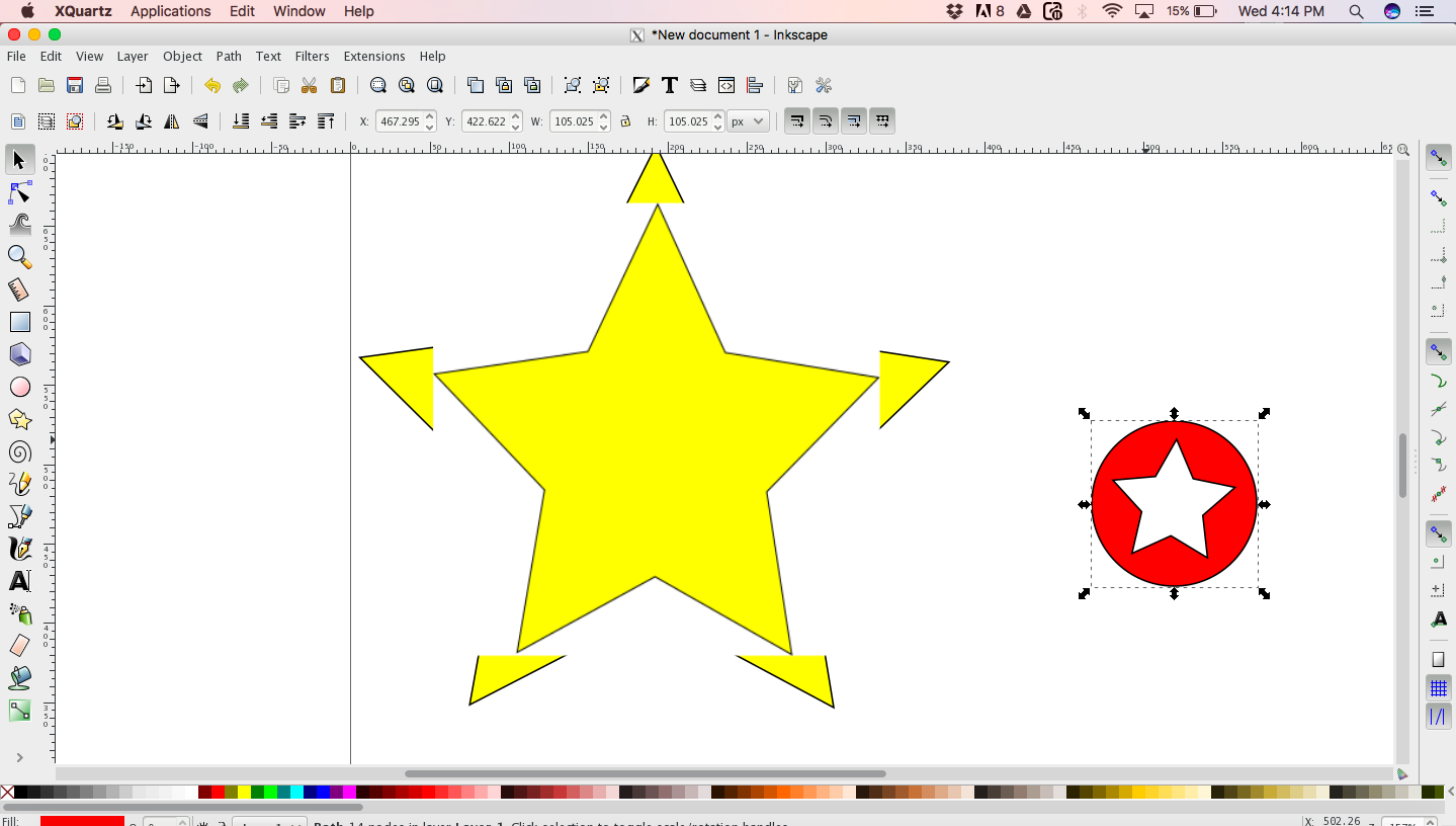
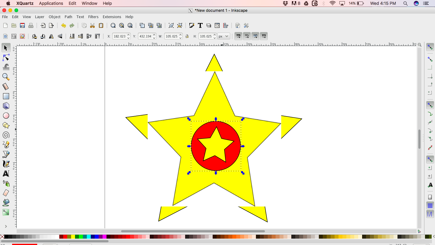
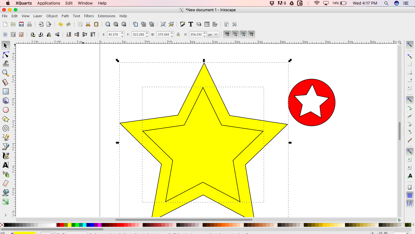
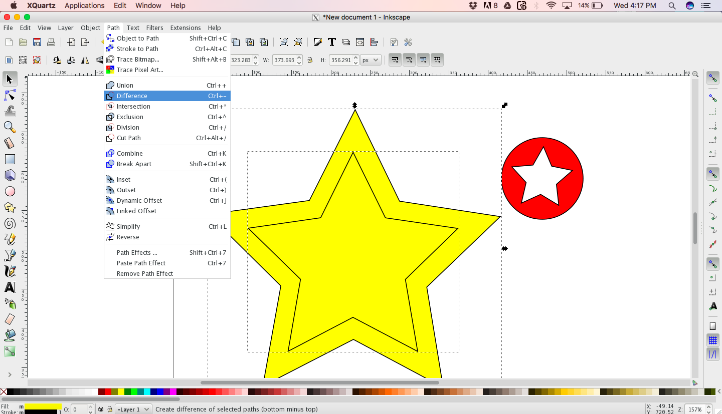
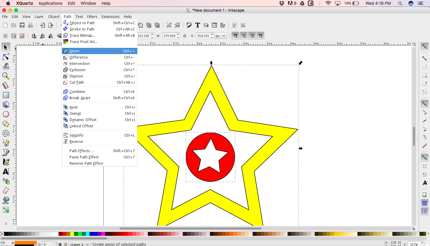
To create my work, I started off with creating a circle, put another star at the middle. I then went on to path -> Union after selecting both the circle and star. There are boolean functions available in Inkscape such as Union, Intersection, Difference, Exclusion, Divion, etc. I tried using some of these boolean function to create the logo. I also played with the pen tool in Inkscape.


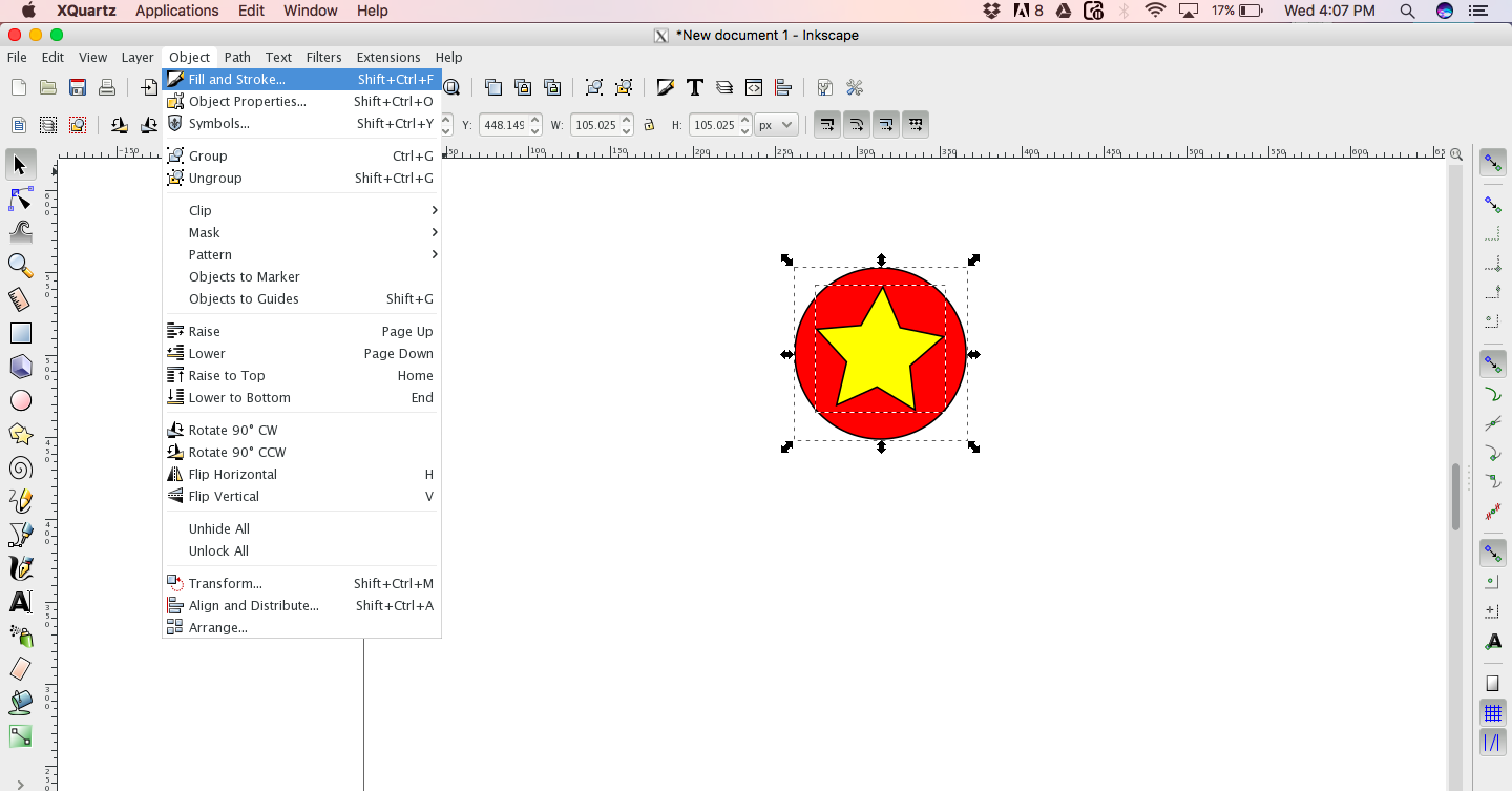
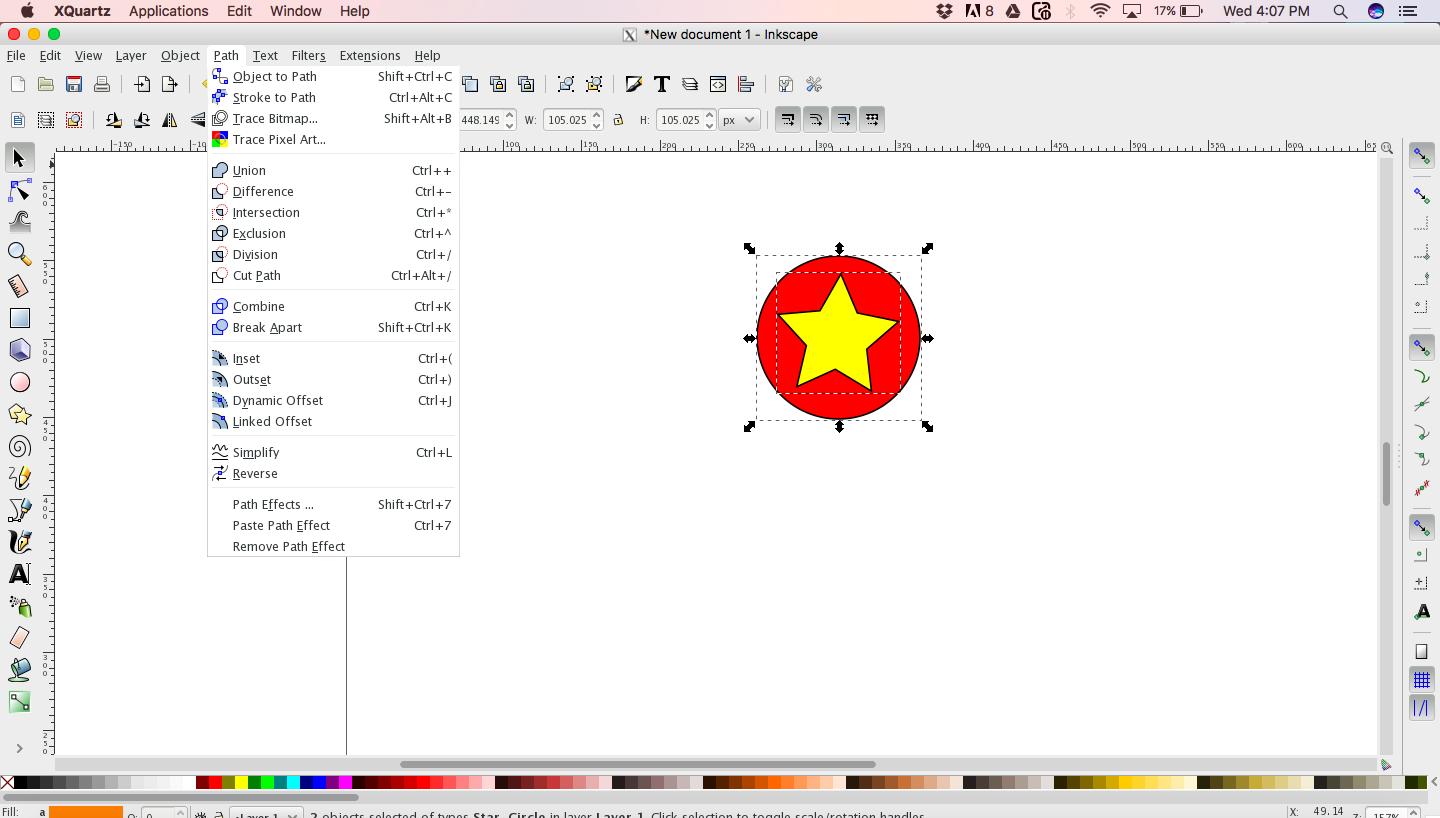
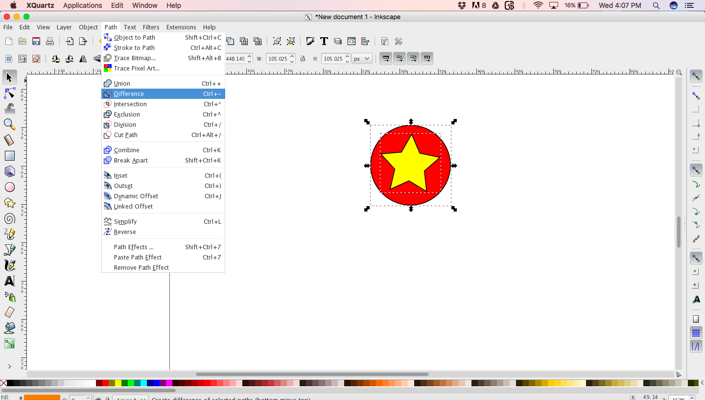
A copy of my Inkscape work is available as Star.svg
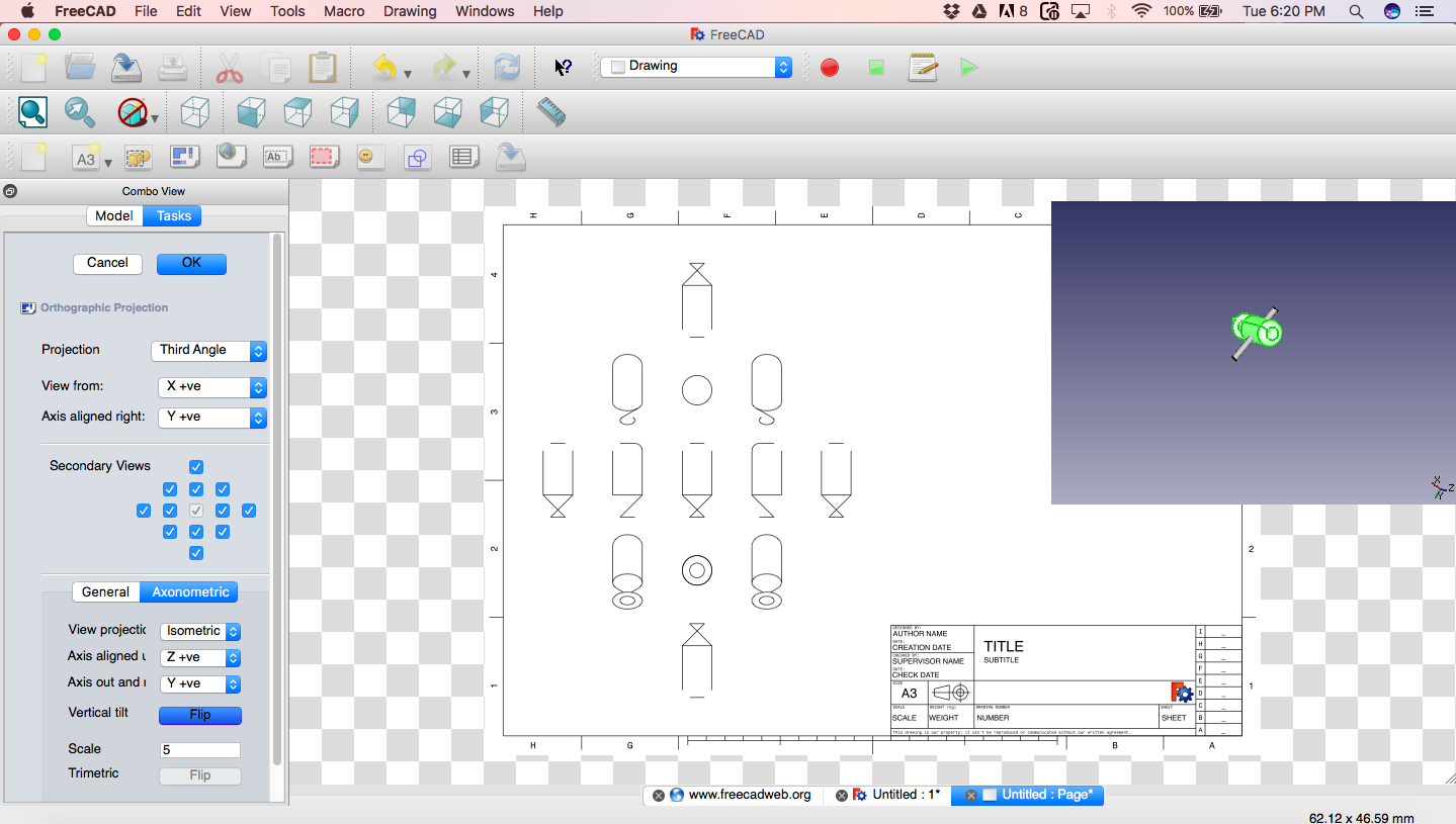
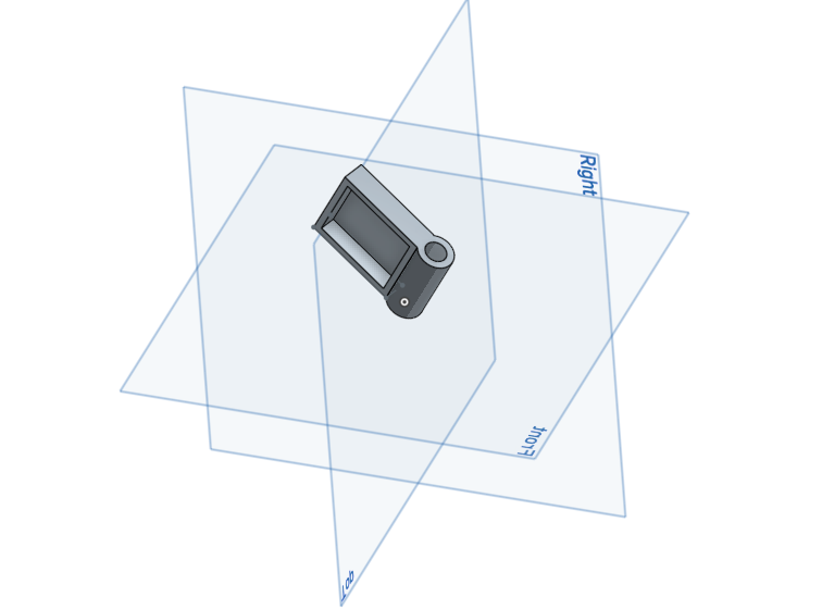
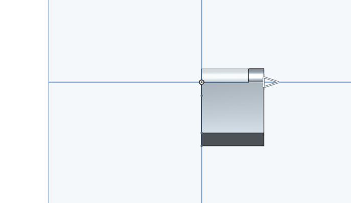
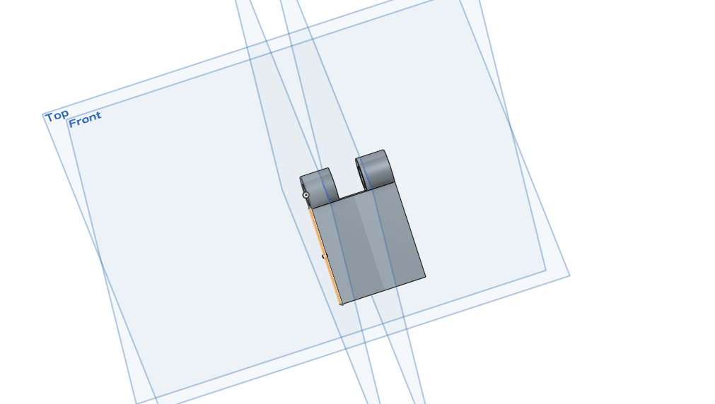
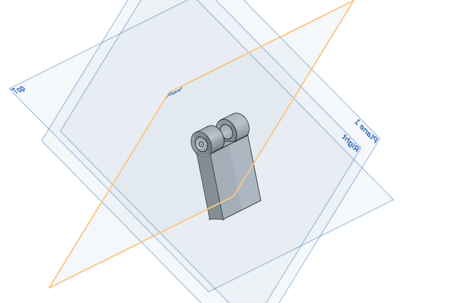
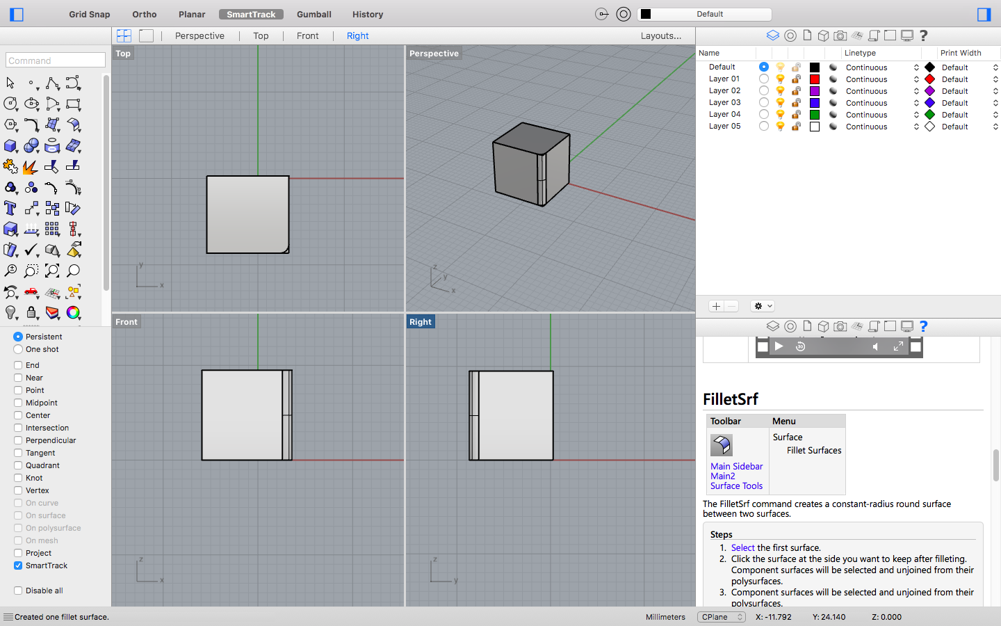
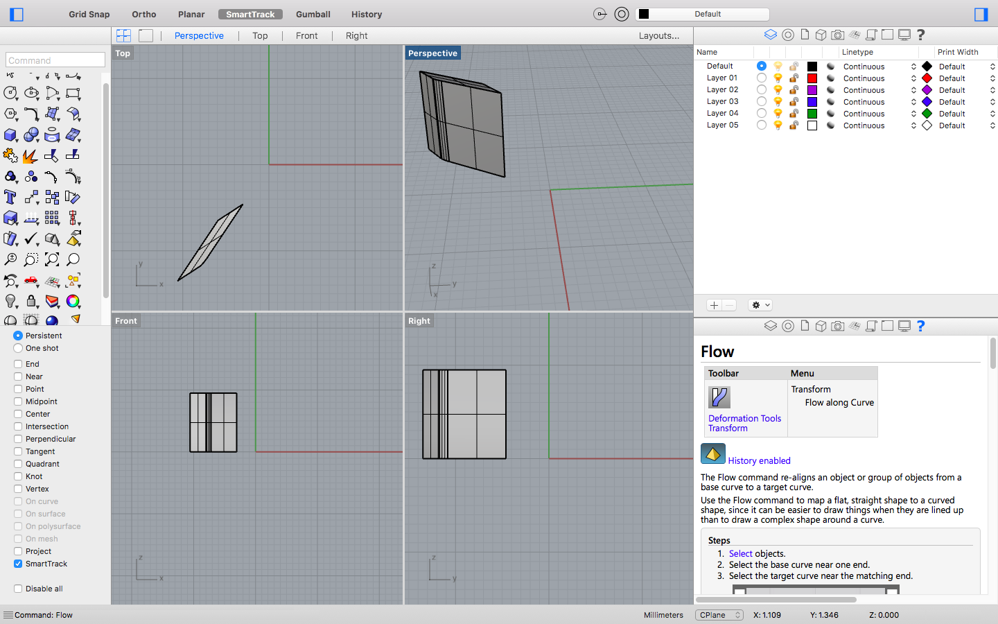
FreeCAD - 2D Vector

What I created using FreeCAD was a 3D object and I was able to create 2D Vector page for all the perspective views of the object that are provided. Check out screenshot. I was not able to save that file separately and it was saved as a bundle with the 3D file. It got a bit confusing for me, and I skipped it to be tried out later.


My Evaluation

Both Inkscape as well as FreeCAD are exceptional tools. But I think I will use Inkscape for 2D Vector designing because its easier.

3D Modeling

The model describes the process of forming the shape of an object. The two most common sources of 3D models are those that an artist or engineer originates on the computer with some kind of 3D modeling tool, and models scanned into a computer from real-world objects. Models can also be produced procedurally or via physical simulation.
Basically, a 3D model is formed from points called vertices (or vertexes) that define the shape and form polygons. A polygon is an area formed from at least three vertexes (a triangle). A polygon of n points is an n-gon. The overall integrity of the model and its suitability to use in animation depend on the structure of the polygons.
-- Wikipedia

OnShape

I started off using Onshape for 3D modeling. Onshape is a cloud 3D application, so you work on a browser. All your interactions are auto saved into the cloud. So this allows you to work on your 3D modelling from anywhere if you can network access. Also the UI are mostly intuitive and they do provide a bit of small info if you hover on buttons.

Im using a public account, so all the work I do are available to all. For making it private, we need to purchase private account.
We can checkout how others work and see how they have done their work and learn from it. We can also make a copy of others project. I came to know abt this only after I did my work in Onshape, so I used a bit of my time for learning it by trial and error.

Onshape also lets us to upload other 3D models we created on other tools. You can do version control on your work. You can create parts and assemble. I think you can import or link other peoples parts for assembling.

This is my work done on Onshape. Following is a gif of some screenshots I took while creating the design.

Antimony

Antimony is a computer-aided design (CAD) build by Matt Keeter and is long-running project under active-development. The UI is kind of unique and works based on nodes and links. I found this tool to be very interesting and pretty straight forward.
You can use mathematical functions to create objects. There is also an interface to edit in Python 3.x script, which is really cool.

We can build both 2D and 3D objects along with converting 2D to 3D also. The viewport is not as pleasing as other tools that I used but still it is not much of a deal breaker.

There are two windows when we open Antimony, ViewPort and Graph. We create our 2D and 3D objects using the Graph. Right clicking on the Graph window will provide the dropdown with all the features Antimony provides. I selected 3D -> cylinder -> x axis. Then a new node is created which can be dropped anywhere on the Graph. There are editing options in the nodes depending on the object the node represents. Basically the length, position, radius, etc for the cylinder. I created another cylinder but with different dimensions. Created another node denoting the union of the two cylinders I created. Since I want the union of both these cylinders, all I need to do is connect/link the two cylinders to input parameters of the union node. And used the output of the union node to another node denoting export.

I also created another object, a glass tumbler by using 2 cylinders won the same axis with slightly different dimensions and used a node to take the difference.

The following gif is created from a screen recording video I took while testing out the tool.


A copy of my Antimony work is available as Head-cylinder.stl and Glass.sb

FreeCAD

FreeCAD is a parametric 3D modeler made primarily to design real-life objects of any size. Parametric modeling allows you to easily modify your design by going back into your model history and changing its parameters. FreeCAD is open-source and highly customizable, scriptable and extensible.

FreeCAD offers lots of features, 3D for different needs like Architectural, Part Design, 2D vector design, etc. Almost all of FreeCAD's functionality is accessible to Python and can be used to integrate with other tools as well.

I started off by building a cylinder and applied Fillet. After camphering the resultant object, went on to create a new group and add all the existing process carried out to this new group. Then I created another cylinder of smaller size and changed the axis and position so that the new cylinder intersected with the existing cylinder. After that I went on to apply the difference of the solids. The resultant object wasnt what I expected, which was a hole in the first cylinder (I think I was applying the intersection on the champhered edge instead of the cylinder solid). So I retraced and stopped at the intersection.

FreeCAD also lets you create 2D figures of the 3D models we create. So I used the drafting set of tools to get a 2D file of my 3D object. I created the 2D page of all the perspectives FreeCAD provided. As part of testing FreeCAD out I created a gif of the screenshots along the way.


A copy of my FreeCAD work is available as FreeCadVector.FCStd

Rhino

The distinct thing for Rhino is that there are multiple viewports in Rhino; top, front, right and perspective view which we can use to control the views dynamically. This gives a good idea on where and how the object is being build. I created a cube from the toolset, we can also use commands to filter out out tool.

Rhino also provides detailed explanation for all the tools at the right-bottom panel. This is very helpful for me, since Im a beginner. I created a cube, then wanted to apply filleting. There are some filleting options, surface fillet, corner fillet, and edge fillet. I used a surface fillet on the cube and applied a flow along surface tool on the resultant object.

I took only a couple of screenshots during working with Rhino. My work on Rhino


My Evaluation

I feel more comfortable using Antimony, OnShape and Rhino. FreeCAD is an exceptional 3D tool, but Rhino's help panel is very helpful for me. If Im to build in Antimony I should have a good knowledge on the parameters for designing, thus both the tool as well as I would be in the same page. When it comes to designing 3D, and my requirement is to go for visual structure and get my parameters correct at a later stage, then my preference would be on OnShape or Rhino. Also OnShape being an online tool would be to my liking if I need to build or assemble anything on the go. The tools that I need were much more easier to get to. GIMP even though it looks easy, I couldnt start of without hitting the tutorials.