Computer-Controlled Cutting

Vinyl Cutting

Machine Description


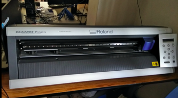
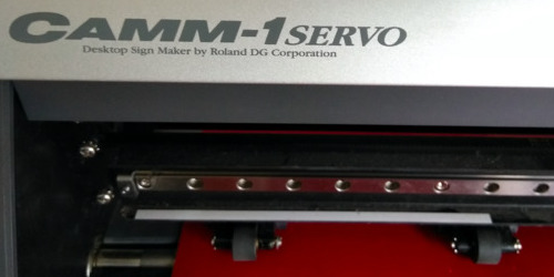
The machine that is used for vinyl cutting in my FabLab is Roland CAMM-1. This device can be used to cut stickers made of copper, vinyl.
It has a blade attached to the head which moves on y-axis making the cutting head. But it could not cut in a single arc; so for that the design is retraced by a tool with multiple short lines thereby creating almost an arc.

Setup and cutting

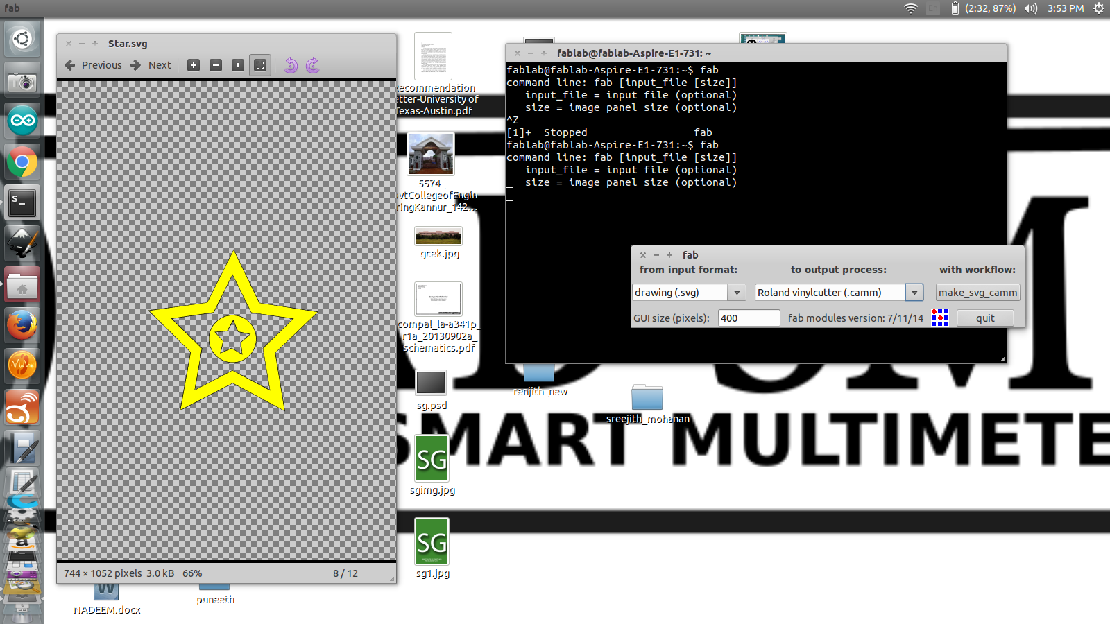
The design files need to be either a .svg or .png file. We can use either Fab Modules or Web Modules to identify the vector path for the machine to cut.

Fab Modules / Web Modules are intermediatory modules that acts between our designed file and the device driver. Using either the Fab Modules or Web Modules you can use all the machines within the FabLab. Web Modules can be accessed via web, whereas Fab Modules need to be installed in our device and can be accessed via terminal.


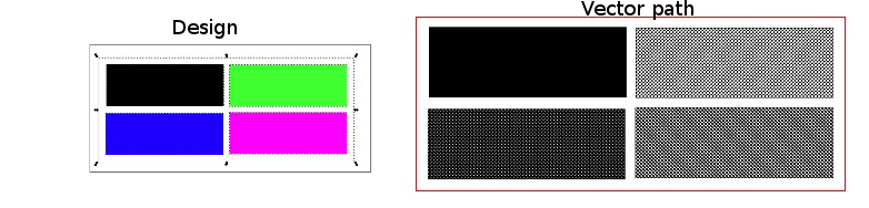
The above image shows my .png loaded up in the Fab Modules and the generated vector path that is identified by the module that is understandable for the machine. The vector path is through where the device cuts.

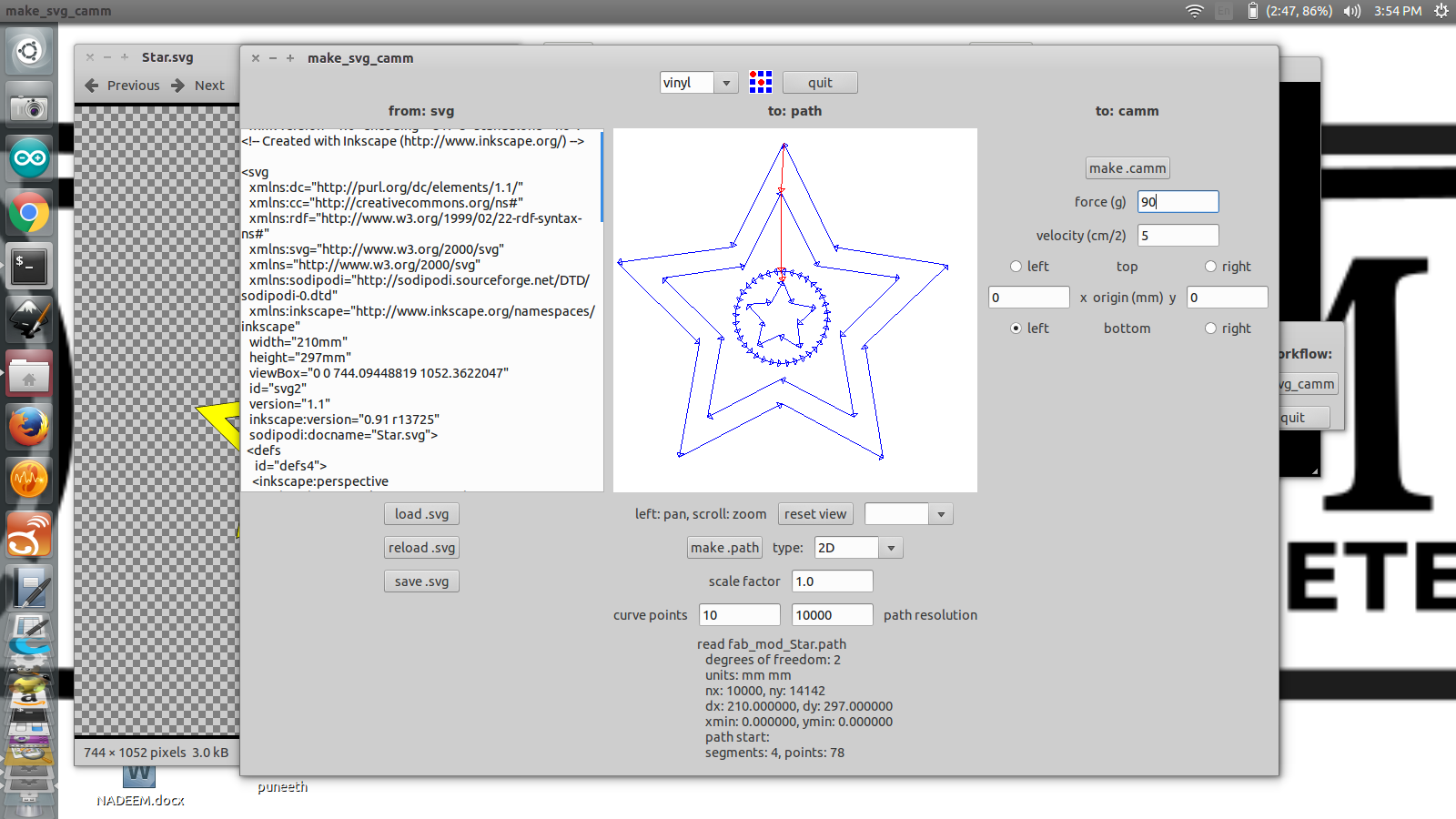
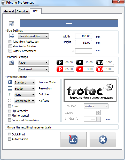
After loading the image and resizing the image (which is important, the size of the image should not be larger the the vinyl sheet width / the device), I clicked the 'make path' button '2D' option to create the vector tool path. The default settings are mentioned below which can be changed depending on the material. For vinyl these defaults were used.

Default Setting for Vinyl Cutter
Diameter(mm) = 0.25           Overlap = 0.5           Offsets = 1           Error(pixels) = 1.5           Intensity = 0.5           Force = 90           Velocity = 5          

Designing

The procedure I used when creating a vinyl sticker is, I got an image and converted the image to black and white only because the vinyl cutter creates a path along the edge of the separation between black and white through which it makes the cut. I used Photoshop for converting the image to Black and White and the end file was a .png file. So I used the Fab Modules to convert my .png file to a vector path the machine could understand.

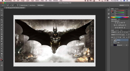
First, I started off with the image I wanted to get printed on vinyl cutter.
Well I thought it would be cool to do a Batman sticker, and started with this.


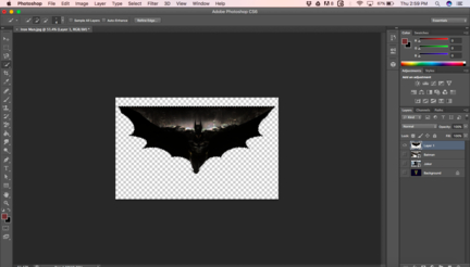
I had to take in another picture because I could not get a distinctive separation of black and white. I tried a few methods to put some distinctive white definiton lines to the image but it did not work the way I wanted it to (mostly that my knowledge of Photoshop is limited :/)

I got another image for cutting. And it looked promising. :)


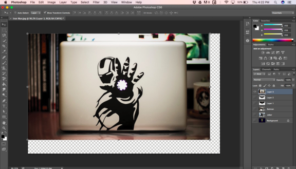
I used the Lasso selection tool and Magic tool to select the areas I wanted to retain (mainly the black colored areas) to get the above image. Then cut the selected section and created a different layer and deleted (or made invisible) the rest of the area. Then applied some contrast and threshold to create much distinctive separation of black and white. But it wasnt quiet working out, I wasnt getting the distinctive separation, neither did it work when I converted the image to bitmap. So I reselected the same areas and applied black paint brush, thus I got a clean separation.

But the edges where quiet raster. I thought the edges would be quiet squarey. I anyway opened the file in Fab Modules after selecting the device (Roland CAMM -1) so that I could initiate cutting.


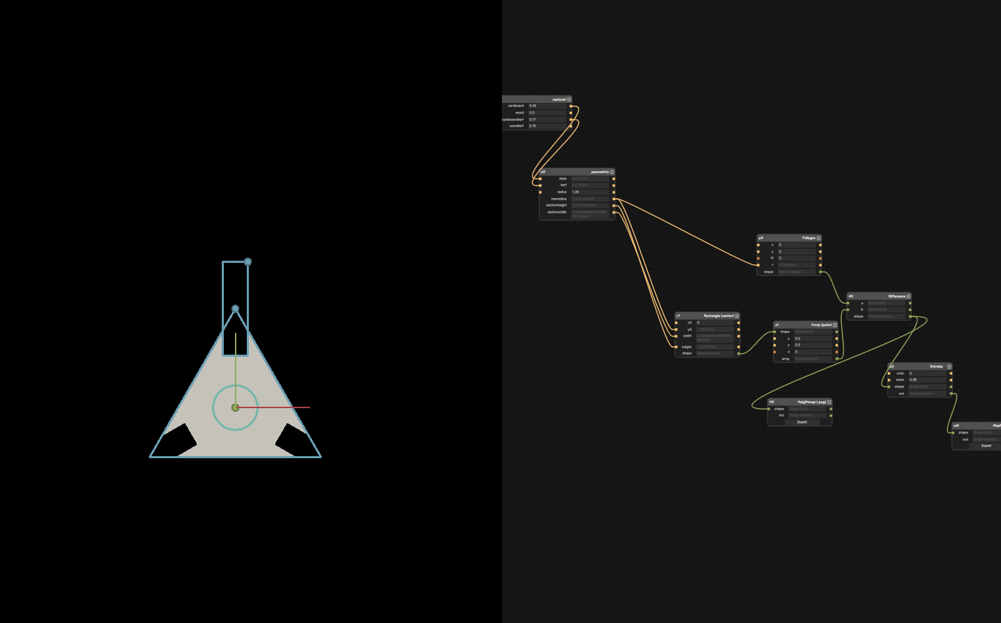
I wanted to try out cutting a .svg file. So, these are the screenshots of my last week's Star.svg design being processed by Fab Modules.


Machine Setup
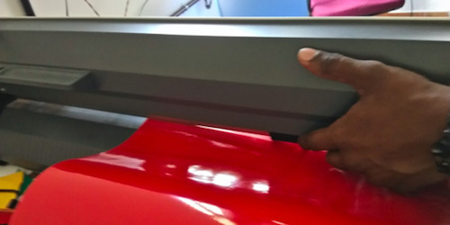
There is push back lever which lifts up the rollers, through which we feed the vinyl sheet.


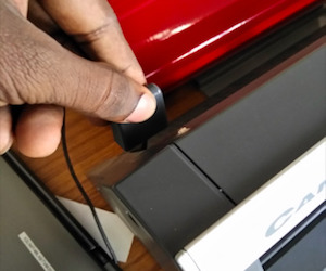
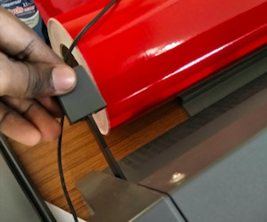
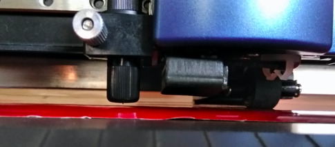
Once the vinyl sheet is fed, adjust the roller which already have sections/slots of track specific for it.


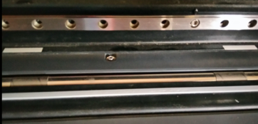
Vinyl sheets with small width would usually remain at the left end along with the rollers.


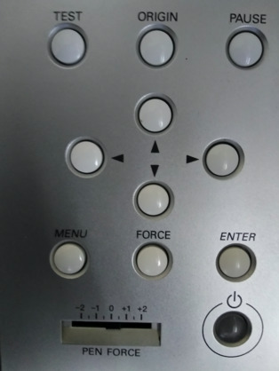
We can also move the cutting head and set the origin from where it starts to cut using the control panel. The device can auto detect the length of the strip of vinyl being feed using some senors within it.


After setting the machine and adjusting the rollers to their allowed slots (there is a track specifically for this) and feeding the vinyl sheet; and setting the origin point by using the controls on the device; Click send it on Fab Modules. Note the device starts cutting from the bottom left. This device has some memory in it, so the files and jobs are stored into it and loaded. So the jobs get preloaded when the machine is restarted.

After getting the cut version from the device, I used a tweezers to remove the parts I did not want(white sections on the vector image). Make sure the blacks and white are nicely separated and review your vector path. I had a small problem with my vector path. It did not detect certain separations because the black and white separations were too small for the machine to detect and the I had to manually create those separations.
Then I placed a maskingtape / cellotape with very small stickiness on top of my design to peel it off from the vinyl sheet. Then placed on top of the surface where it need to be placed. And slowly removed the maskingtape / cellotape leaving behind the sticker on the surface. A gif of all the things done after cutting.


Original Design File

Star.svg
IronMan.png
IronMan.psd

Laser Cutting

Machine Description

The Laser Cutter thats at our FabLab is Trotec. It is Carbon dioxide laser which can cut throught cardboard, craft wood, acrylic.

When the laser cuts through the materials, it ejects harmful gases, so there is an air filter attached to the laser cutter to suck out these gases. Its also important to be at the laser cutter when a job is running and to keep the air filter running. The air filter is also from Trotec.
The laser cutter cuts through the red color and engraves throught the black color of our design files. Different materials need different Power, Velocity and Frequency settings to cut through and to engrave.

Setup and cutting

When the machine is switched on, the base plate starts its way down. On the plate rests a honeycomb structure on which we would be placing our cutting material.


Once both the laser head and the base plate gets reset, we can open the lid, and move up the base plate using the control panel. Place the material for cutting, and use the focusing tool to identify the exact focusing distance. Hang the tool on the extruding edge of the laser head and continue moving the base plate till when the focusing tool just falls off. Thats the correct focusing distance of the laser.


This is a block we tested with different power settings to engrave. We mapped different colors with different powers and velocity for engraving. Power for Black color was 80, 60 for Blue color, 40 for Green and 20 for Violet. Velocity was fixed as 10 and Frequency was not changed (auto).


Building Parametric design using Antimony

Antimony is a software that can be used to create 2D, 3D designs. It took me lots of trial and error to understand how I needed to create the design using Antimony. So the following 3 screenshots are the end products of my designs. All these files are downloadable at the end of the documentation.


One advantageous thing about Antimony is that there is very little distraction. You can find all the features available by doing a right click.

The concept of making a design parametric is that if you change one dimension, all the rest of the dimensions also needed to get scaled automatically. So for doing that you need to link all dimensions and coordinates accordingly among each other.
Note it could get confusing but its important you start using Antimony only after creating a lookup design somewhere with all the dimensions and with all the mathematical calculations required for linking among the different parts/dimension of the design. I learned the hard way. I went through multiple iterations of the design only to find some part failing to scale automatically.

I used only a few nodes to create all of my designs, namely, Rectangle, Array, Array (Polar), Script, Polygon, Union, Difference, Export, Rotate(2D), etc.

All these nodes can be altered depending upon our need, but you need to change the code within that node accordingly. I actually did not change the code much of these nodes except the Script node. I used the Script node to take multiple inputs and create different linked outputs that acts as the inputs for other nodes. Couple of screenshots on a node named 'Parametric' that I created specifically to handle parametric calculations.


It would do good if you know the math module in python. You could use modules to build mathematically integrated designs.

The modules that I imported. The following is the code for my HoneyCombFloor radius calculation I did using Script node.
import fab
import math
title('parametric')
input('thick', float)
input('kerf', float)
input('radius', float)
newradius = radius + kerf + (2 * thick / math.sqrt(3))
output('newradius', newradius)


I then used the output from my node named "parametric" to the polygon radius. 's0' is the name of the node for referencing. Each node can be given a different name as well that is for reference, when you are linking or when you are referencing a particular node in another node.

Title refers to title of the node. You can copy the node by using Ctrl + C and paste it Ctrl + V.

I exported my design from Antimony in .png format and used Inkscape to convert it .svg format along with changind the color to red.

Converting the png file to svg and changing the colors of the design for laser cutting.


Job Control

When the Inkscape file is send to print, we can change and set the material, the velocity, the power and frequency and save those changes as well, and then forwarded to Job Control.


The honeycomb window is the linked to the honeycomb structure within the laser base. It acts as the base on which our material is placed. The black box is our job which we can drag anywhere on the honeycomb window, and the device will start cutting at the exact point corresponding to the honeycomb base as well.

Kerf Finding
Kerf is the width of area that the laser burns up. So when the laser cuts along a line, a portion gets burnt off on either side of the laser. Its important when designing a parametric design to apply an offset of kerf on our designs. There are multiple methods by which we could do find kerf.
Due to the laser burning edges on either sides of a line, the output we would be getting is a bit lesser than what we had applied on our design. So we need to put an offset for kerf on our designs and it would be half of kerf. Also its important to use the top side of the material when measuring the kerf. This is because the laser gets deviating after it converges at the focus, there my cutting the material's bottom side at an angle.

The kerf of the laser for different materials would be different.
Kerf for craft wood is 0.3 mm
Kerf for acrylic is 0.488 mm
Kerf for cardboard is 0.35 mm

The angle of the laser is also found to be 0.074 deg.


Parametric Honey Comb Press fit kit


Challenges faced
When I designed for this press fit kit, I did not consider the thickness of the material when it gets assembled. You can see that the structure starts slanting/flexing a bit when adjacent walls were connected. Also using the connector, it aggravates the problem.
I fixed the issue by changing the code related to honeycombwall radius by linking the thickness of the material to it. Thus if a different material with different thickness is used for the honeycomb structure, the radius of the honeycombfloor will also change accordingly.

I could also have verified my design, if I took an mesh file and open it in onshape and tried to assemble all my parts.


Original design files

My Antimony files for this press fit kit.
HoneyCombFloor.sb
HoneyCombWall.sb
HoneyCombConnector.sb

Exported all these files from Antimony as .png files


Then converted all these files to .svg by using Inkscape