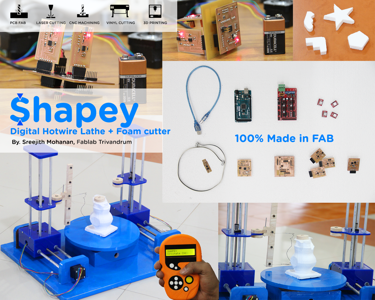
SHAPEY, Multipurpose Hotwire CNC
Index
- Inspiration
- Ideation
- The Big Picture
- The RoadMap
- Getting Ahead with the CAD Designing
- Making the mechanical parts
- Making the circuits
- Connecting the boards
- Making the limit switches
- Time to code
- The first moves
- Version 2: Including the rotary axis
- Making the hotwire holder
- Coloring the baby
- The final avatar
- Making the lathe shapes
- Working the machine
- Version 3: Developing the remote control
- Problems and Solutions
- Conclusions
A. Inspiration
As digital fabrication is replacing almost all of traditional
manufacturing process. CNC machines and their importance are all on an all time rise.
Earlier mass production was done by cnc machines but now a days even the early stage
prototyping are done with the help of CNC machines. The FAB Labs as a global institution is
also contributing to the fast absorption of these kinds of machines in the society.
I know atleast a dozen of people who bought CNC machines after vising our fab lab.
It opened up a new way to improve and improvise what they have been doing in a better and
smart way. These machines provide quick prototyping
functionality with very good finish comparable to Industrial products and some machines even go
beyond just prototyping. So i like to believe
that CNC machines are the key to personal fabrication and beyond. I believe who ever unlocks and masters
the secrets of CNC machines will hold the key to the next generation of personal fabrication.
Some might believe that in the future we will make all the products which you want by yourself,
but i would like to take it a little differently, i believe in the future if we want a product we will
make
the machine which will make that product for you. Its personal machine making rather than fabrication.
Inspired from all those wonderful CNC's in our lab i am making a CNC machine as
part of my final project. With this experiment and experience i want to explore the possibilities of
cnc machines in making great products. I want to make a complete stand alone CNC
machine completely from scratch but in the time frame allotted for completing the project, i wont be
able to do it entirely therefor
my plan is to go ahead with a helical development pattern. I have made a road map on how i will make a
full
fledged CNC machine which starts off as my final project in the fab academy.
B. Ideation
I have three weeks down the line and i have decided to make a machine and i am building it from scratch; No commercial boards, no opensource firmwares, building everything from ground zero with the knowledge i gathered in my six months of fab academy. Its time to look around and find the right kind of CNC machine which is useful enough and simple to make in this short period of time. After quite a bit of googling i decided to make a hot wire foam cutting cnc as its end effector is as simple as a hot wire. Also foam is easy and cheap to handle. This will let me focus on the machine building aspects rather than the issues with the end effector. If i choose making a 3d printer or a pcb milling machine, i have to spend atleast a couple of weeks fixing the end effector. So the choice is obvious. Its the CNC foam cutting machine.
b1. No! not just a normal foam cutter
I know i want to make a simple foam cutter first but i just dont want it to be as ordinary
as it can be.
I want it to do more that a normal foam cutter does. I simply started making a drawing of the foam
cutter and during the process i was thinking
what all additional innovation can be brought on it. This is the initial drawing i made.

Initial drawing of SHAPEY
The following is the model which inspired me with the drawing.
Foam cutter inspiration
My design has 4 steppers ; 2 inside the box and two on the sides of the frame. I have the hot wire
running in between the two arms.
This is good to get started but i wanted more. I brain stormed on it and identified a couple of other
uses of the same machine.
- I can do digital hot wire lathing just by introducing a rotary axis in the middle.
- I can make shapes with the hot wire and use the machine to cut different shapes with that
- Instead of moving both the arms together, i can make them move separately and bring in extra degrees of freedom
- Now the combination of all these, The rotary axis and the independent motion of the arms gives tremendous possibilities to shapes which can be made with the machine.
Also initially i was planning to make the machine controlled by the computer, but later i identified
that it
is much better to avoid that as,
the computer often serves as the medium to file sending only and by putting an sd card reader in my
machine
can make it stand alone.
Another point i identified is that, in machines like shopbot and in ultimaker, i always wanted a remote
control, rather than just go near the machine
for every small operation like turning off the light and choosing the model to print or to set zero(in
shopbot), i wanted a remote control which does all that.
But the problem is that it needs to be a part of the system plus it should be mobile. We wont be able to
put
two lcd displays for the main housing and one
for the remote control. So a better solution is to make then separate and the main housing will act like
a
holder for the remote control.
You can refer to the diagram below.
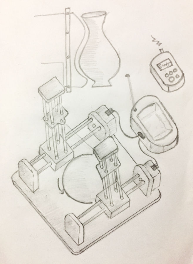
Final design
You can see that the main control circuits all go into the box attached to the machine and the remote
can in
fact be place on this box. Thus they
are part of the same system but gives mobility as i wanted. This remote will further comes handy when
you
are using the machine as a lathe.
At this stage i had an idea of how my remote controller is gonna look. I make a drawing of that.
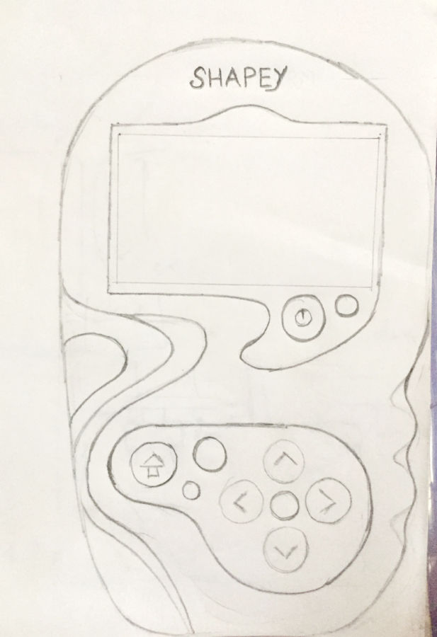
Controller design drawing
C. The BIG picture
After all that research and brain storming. These are the final feature set of Shapey; Oh i have found a
name also :)
- Shapey is a multipurpose hot wire CNC
- It can do normal 2d shape cutting
- IT can do lathe operations
- It can move its arms independently to create complex shapes
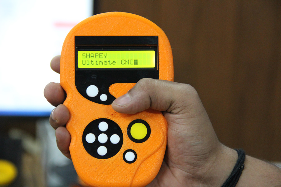
- The machine will have a remote controller, with display showing the status.
- The remote controller will have the sd card slot to put the files to me cut.
D. The Roadmap
Thats a lot of feature set. Doing all that in 2 weeks time is not quite possible specially when you are making everything from scratch, boards, code everything. So what is possible is to adapt a helical development pattern, cut the development into stages and complete as much as possible before the presentation date. The following are the Stages of development.
- Version 1 : This version of the machine will be a basic foam cutter able to cut 2d shapes from an instruction set send from the computer. Initially i will manually generate the instructions send, and later will make a gcode to instruction set conversion software
- Version 2 : Once the machine starts to make its initial moves i will add the rotary axis and will introduce the hot wire lathing
- Version 3 : Here the machine will get the remote controller and it will start to work stand alone detached from the computer.
- Version 4 : Now i will make the arms move separately together with the rotary axis thus being able to cut complex helical structures.
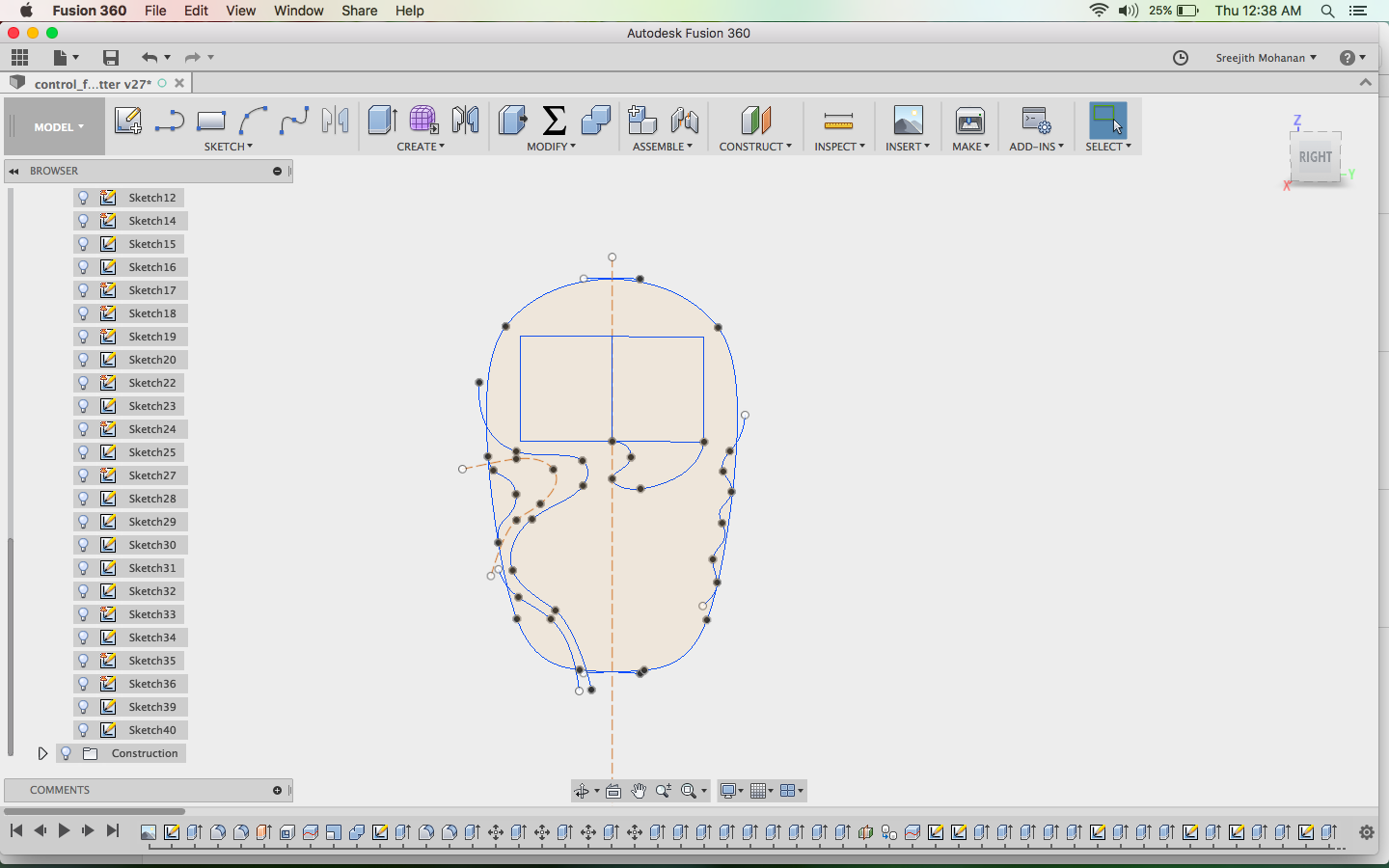
E. Getting ahead with cad design
I am using fussion 360 for my cad designing. Its an wonderful tool and i have been using it
throughout the course.
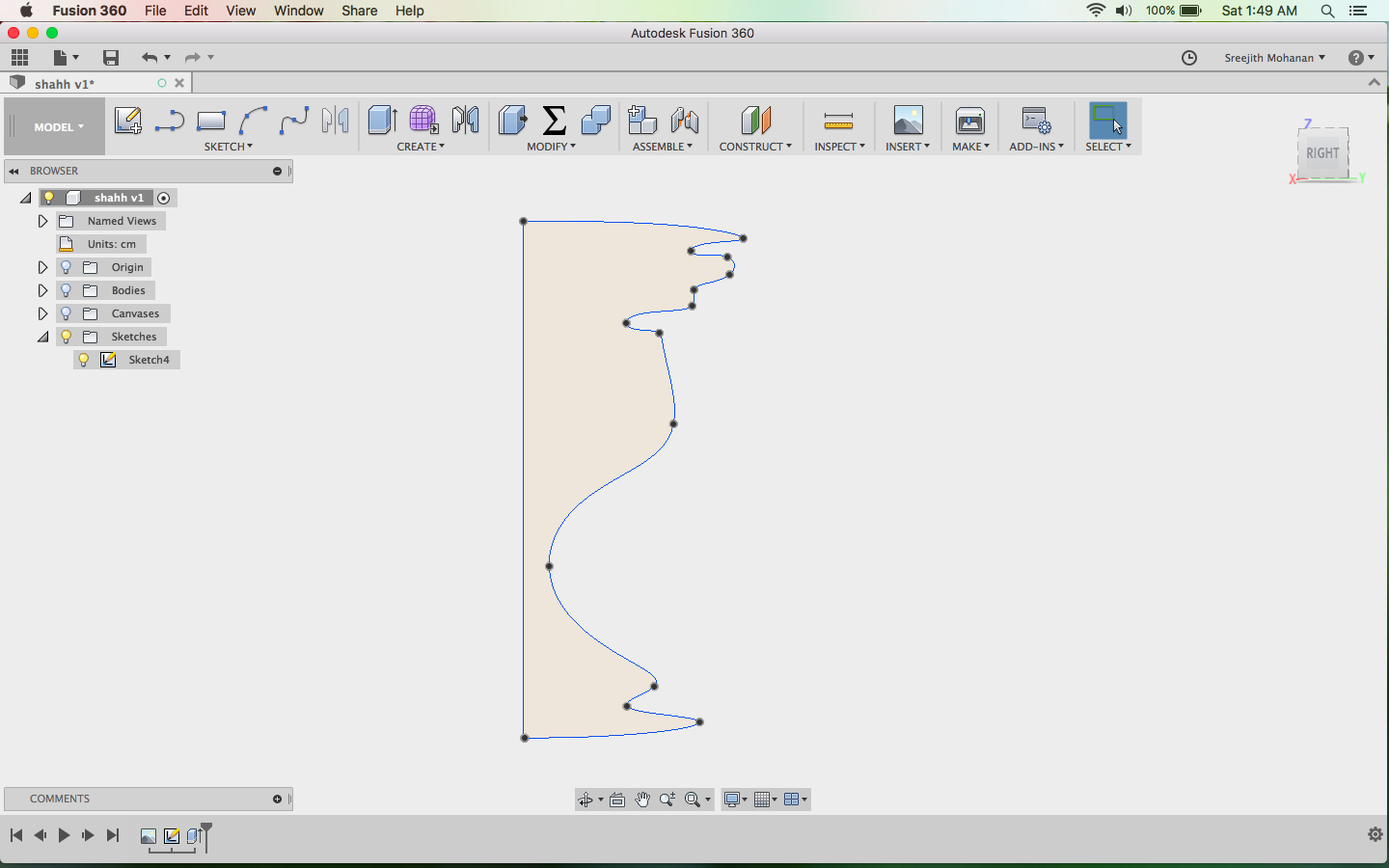
As always with fussion, you make the sketches first, push/pull extrude then and get your shapes. One
major constrain i had was the dimensions of the
spaces and steppers. I am using the steppers, alluminium rods and the spaces within the MTM kit. I could
not find the CAD models of these parts online
so i had to measure each on them with the vernior and make sketches and adjustment in the designs to
include them in the frame properly.
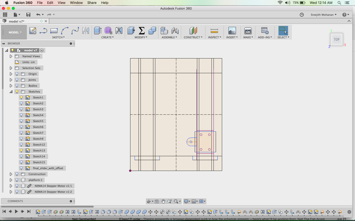
First the sketches were made
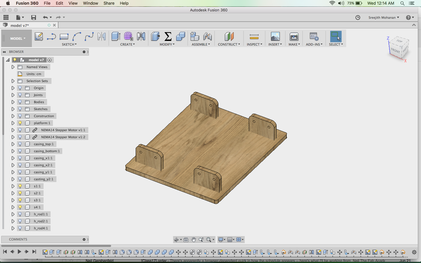
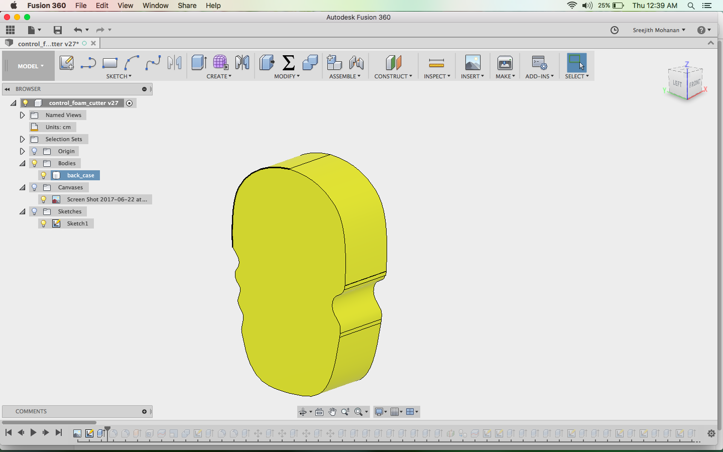
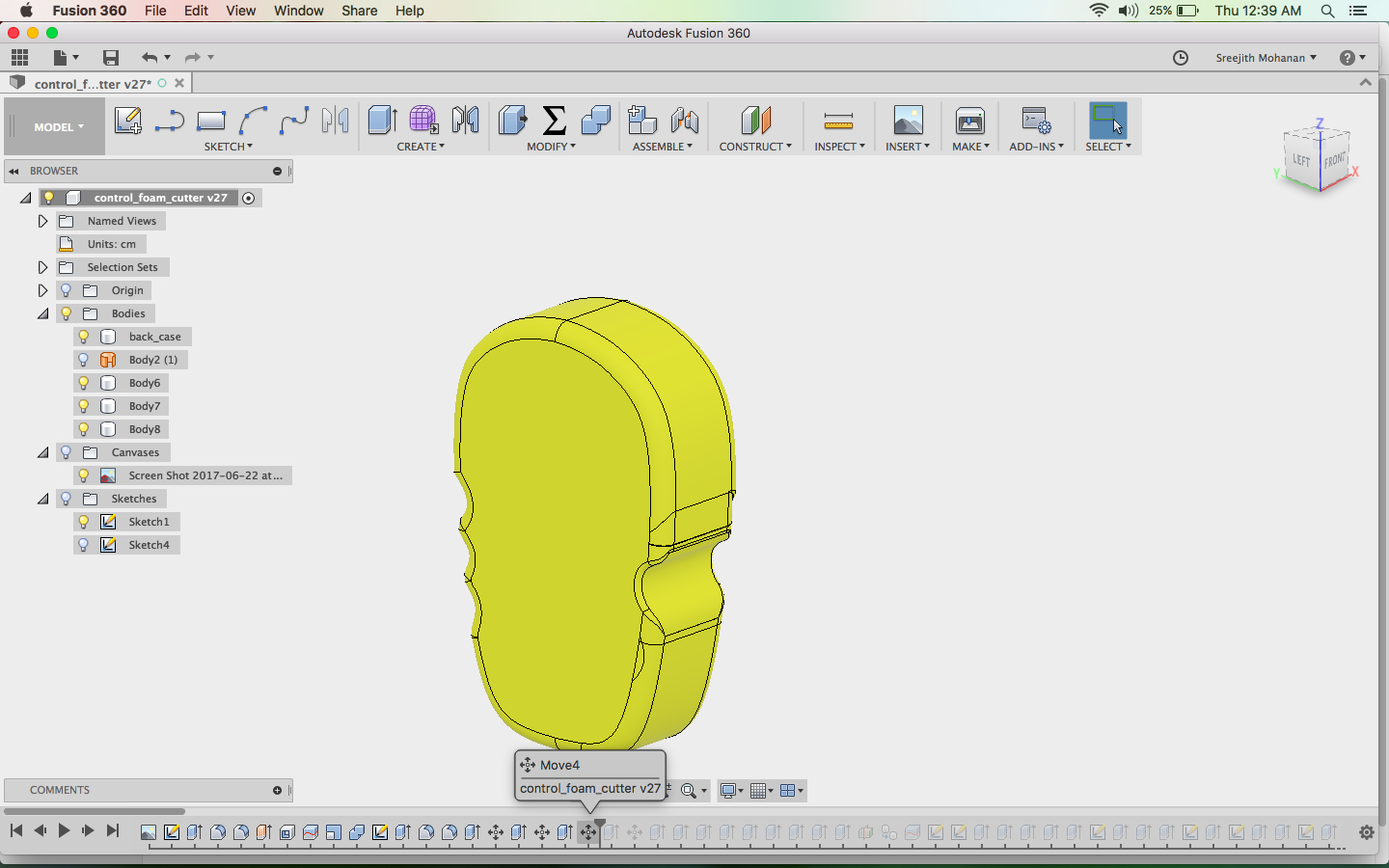
Sketches where extruded and moved around to make the body and frame
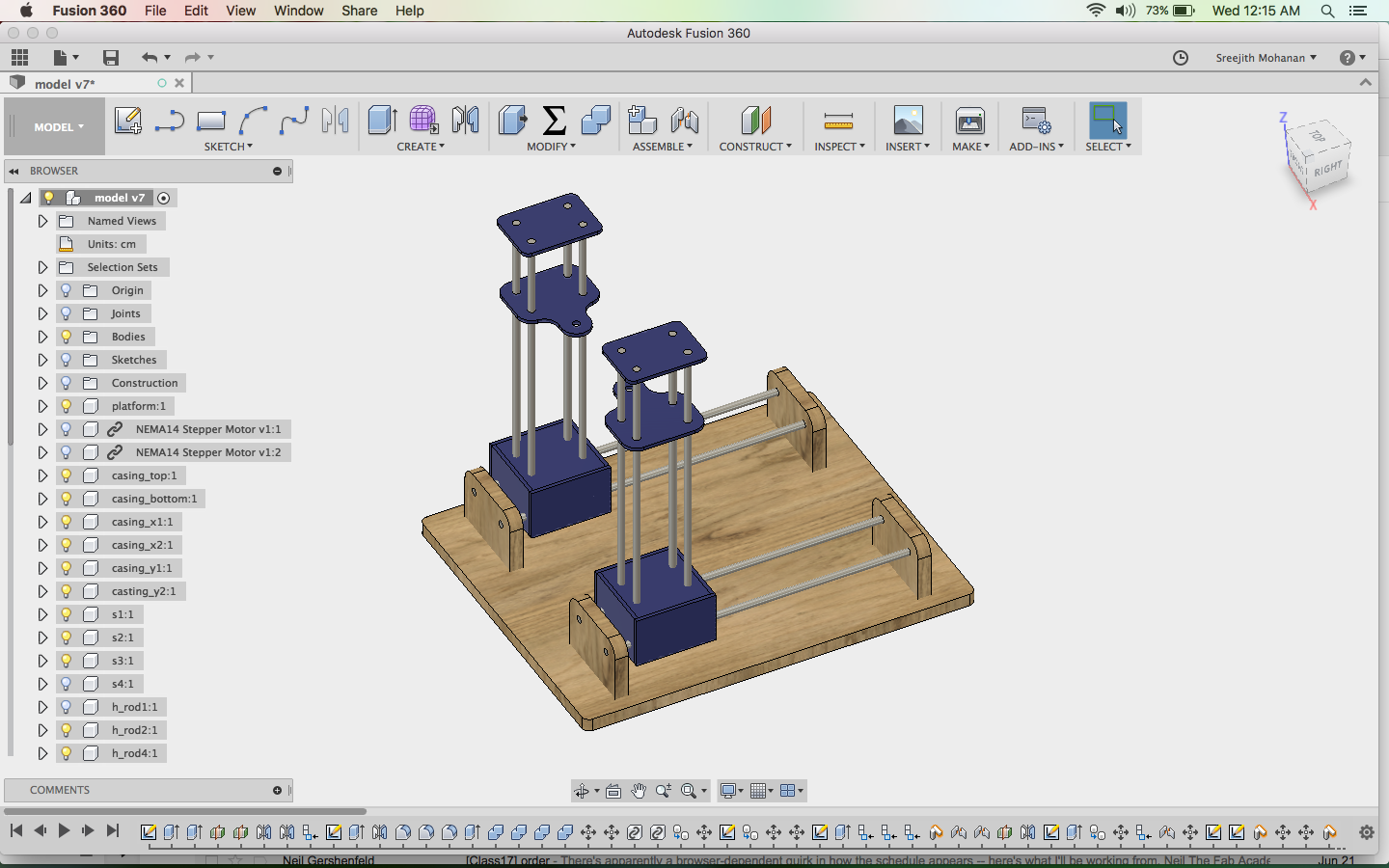
The rods where added
Steppers where added
e1. The cad models
My cad design for the foam cutter
Full fussion file for the model
F. making the mechanical parts
The base of the machine is make in plywood with shopbot and the moving parts where cut in acrylic.
f1. Cutting the acrylic
I created the dxf files from the above design and opened them in rhino. I then tried a couple of test cuts to
make sure that the spaces will fit
into the slots properly. With the data gathered with experimentation i could find the exact size needed
for the spacers to fit in.
Even though you compensate for the kerf while cutting the acrylic parts for making the machine, there are chances
that the spaces will either be loose of too tight that they can be inserted. Thus its important that you find the the right sizes by trail
and error before making the actual cut. Else you will waste a lot of material. In my experience kerf can get you close to that value but not exact.
This is beacause of the material properties, some materials will be hard and others can take little bit of compression
I am attaching the rhino file which has all the cut shapes used in my machine. I cut these shapes in 6
mm acrylic.
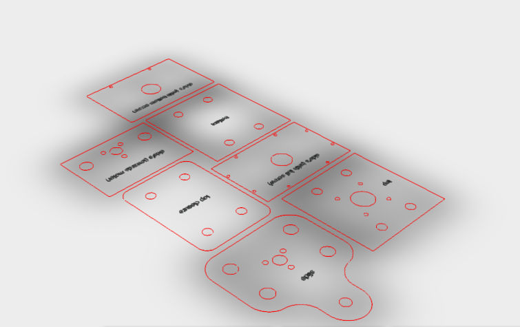
The profiles for cutting the acrylic
Full Acrylic cut
files in rhino format
Full Acrylic cut
files in dxf format
f2. Joining them together
The designs where made in such a way that they can be sicked with a solvent like chloroform. Chloroform actually melts the acrylic and thereby fuses them together creating a very strong bond. All the acrylic parts where joined using chloroform
f3. Making the base in shopbot
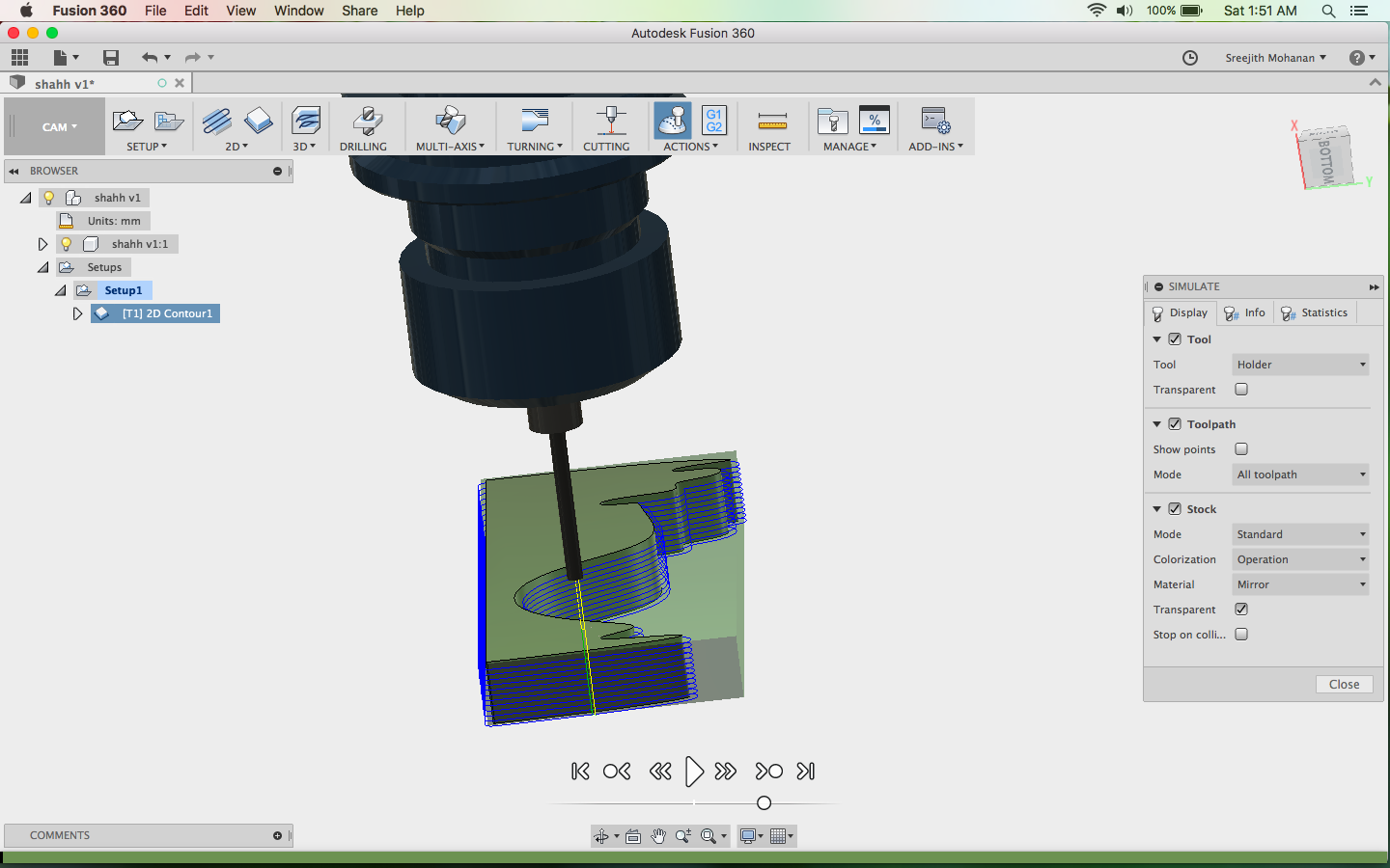
I used fussions inbuilt CAM facility to generate the stp file which can be used directly with the
shopbot interface.
I had provided enough allowances and dogbone fillets for proper fit. I make the base and put on the side
supports by press fit.
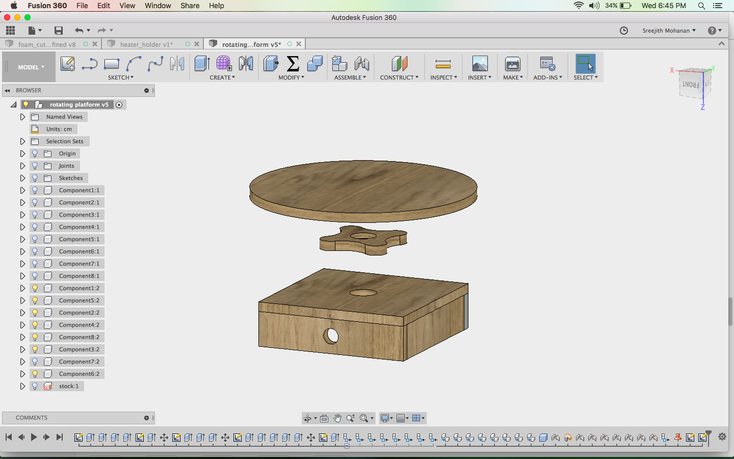
I have made few changes from the initial cad design to include the rotating platform in the version 2.
The new cad files are given below.
Shapey platform 3d view
Fussion file
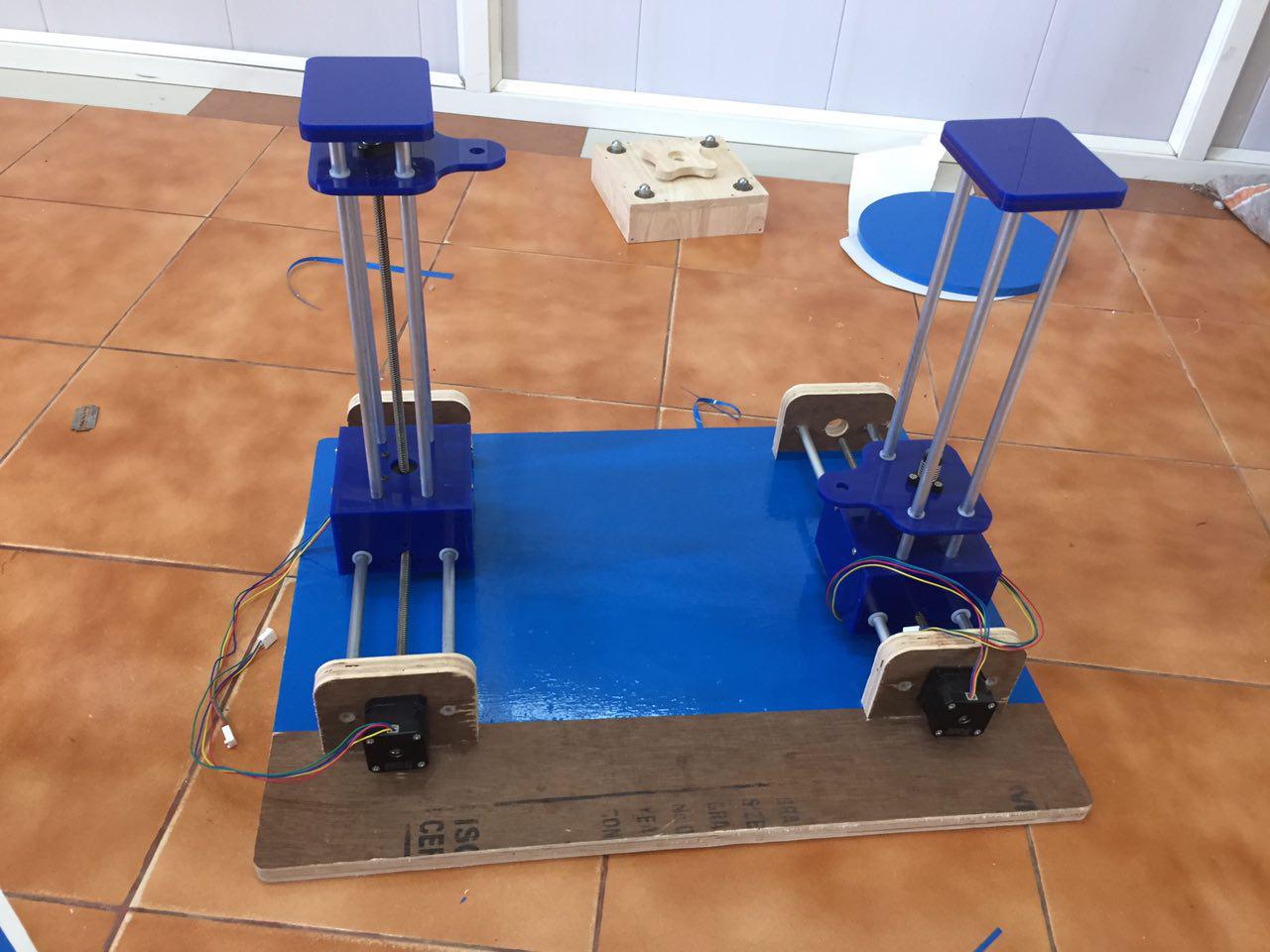
f4. The final assembly
Lastly i assembled all the parts togather.
Assembling acrylic parts
Final Assembly
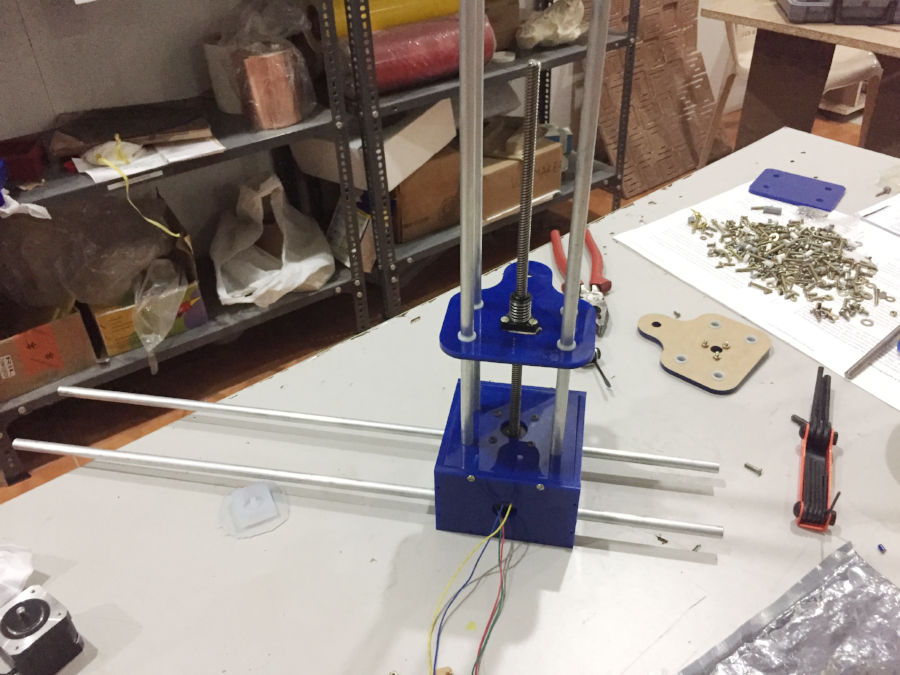
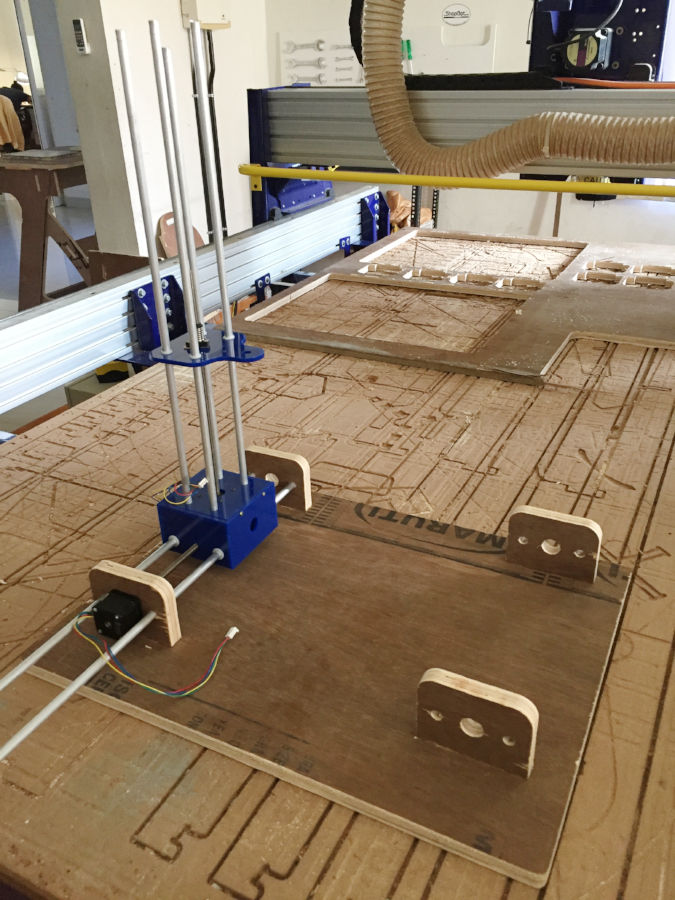
f5. Its show time
These are some photographs of finally assembled mechanical parts. I have not cut the extra length of rods yet.
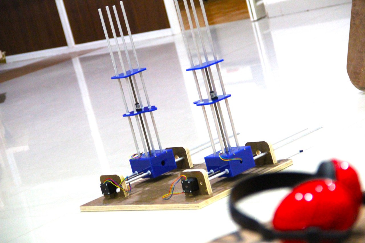
Assembling acrylic parts
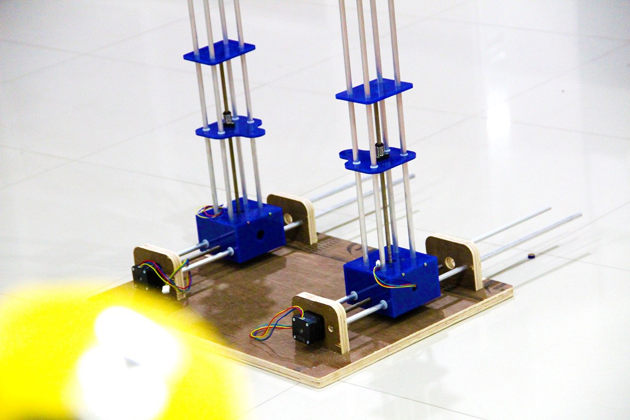
Final Assembly
g. Making the circuits
I am making all my necessary circuits my myself. I am reusing the micro controller board from the ouptut week . The boards i will need are a sheild board for putting the stepper control circuits and a stepper control board for each stepper. I am having 5 stepper including the stepper for the rotary axis so i need 5 stepper control boards. Also i need to make a power control board to control the heating coil and for turing on and off the power into the steppers.
g1. The microcontroller board
As mentioned i am using the same board from my output week. The details are given below.
schematic diagram
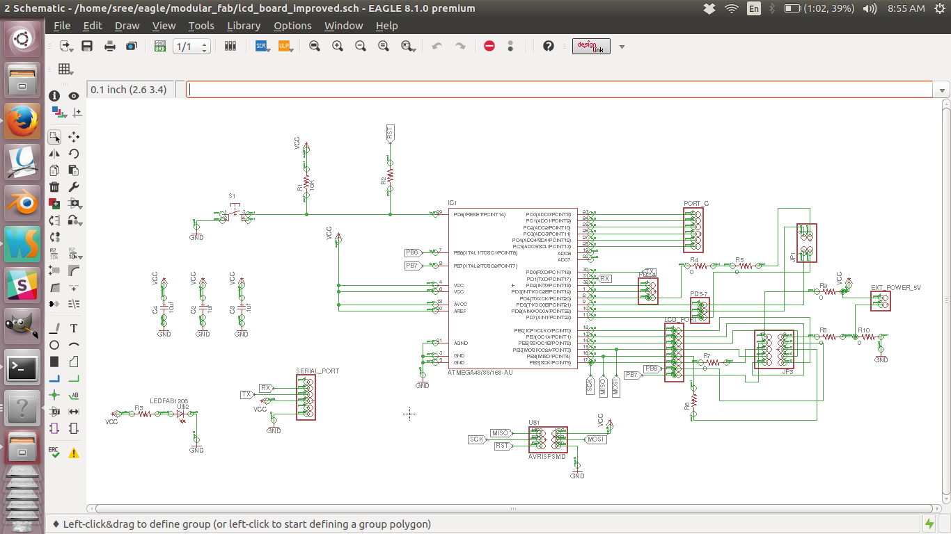
board
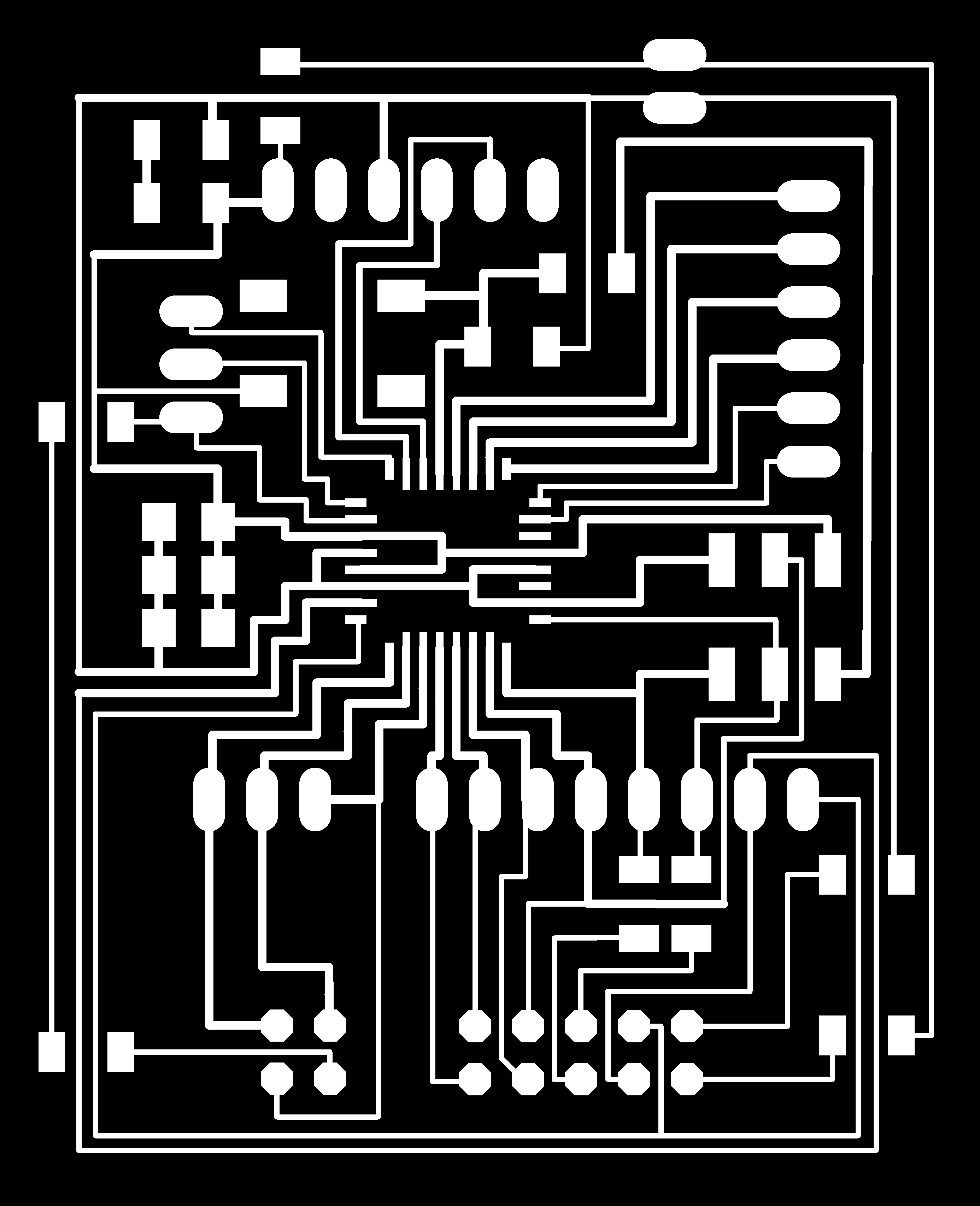
Trace file of the MC board
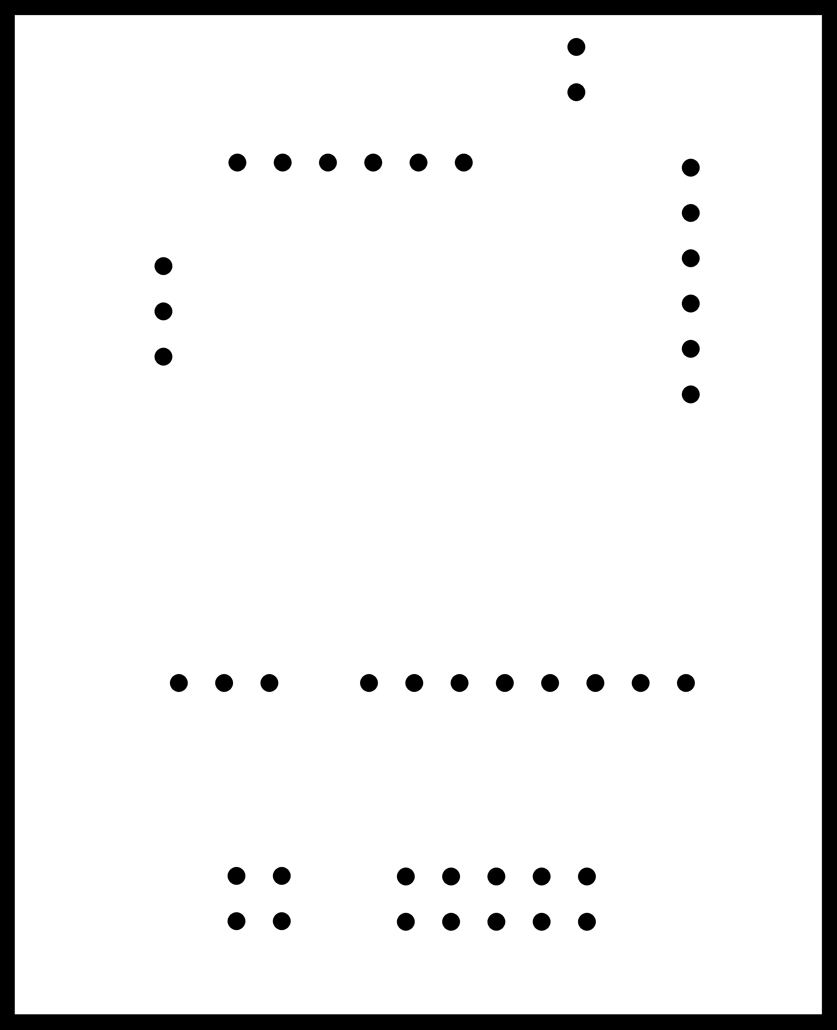
Cut file of the MC board
Schematic design file
Board design file
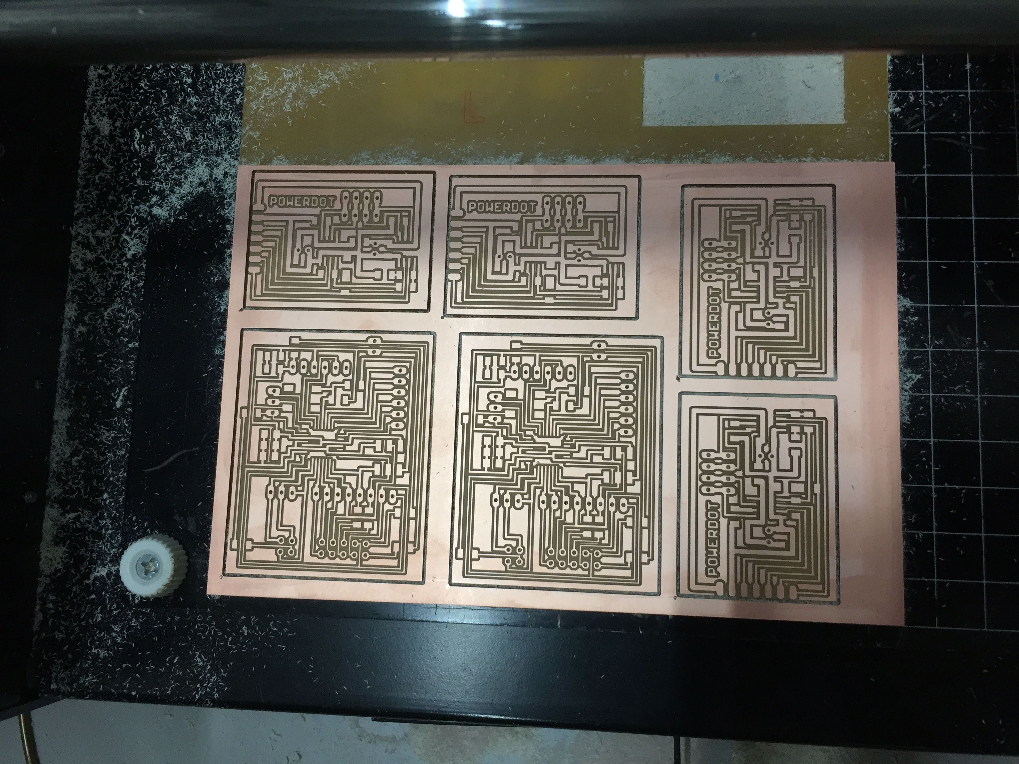
Milling boards at once
Finished board
The following are the photographs of finished board.
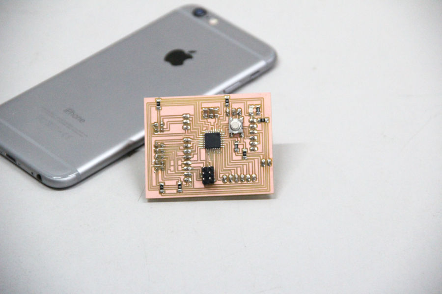
Finished board
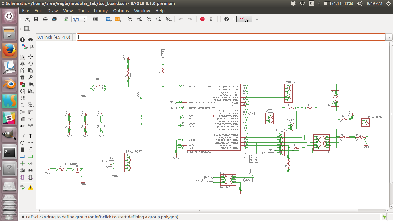
g2. The sheild
As the micro controller board is a generic one, i had to make a sheild board to put all my stepper boards and other controls.
The design files are given below. You can see that i am putting the resonator on this board.
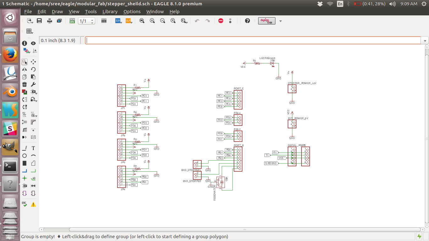
schematic diagram
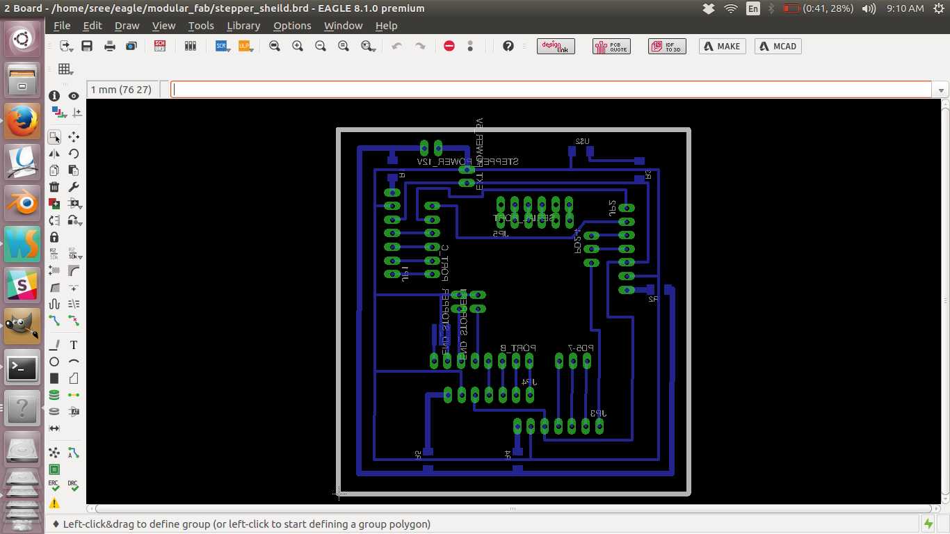
board
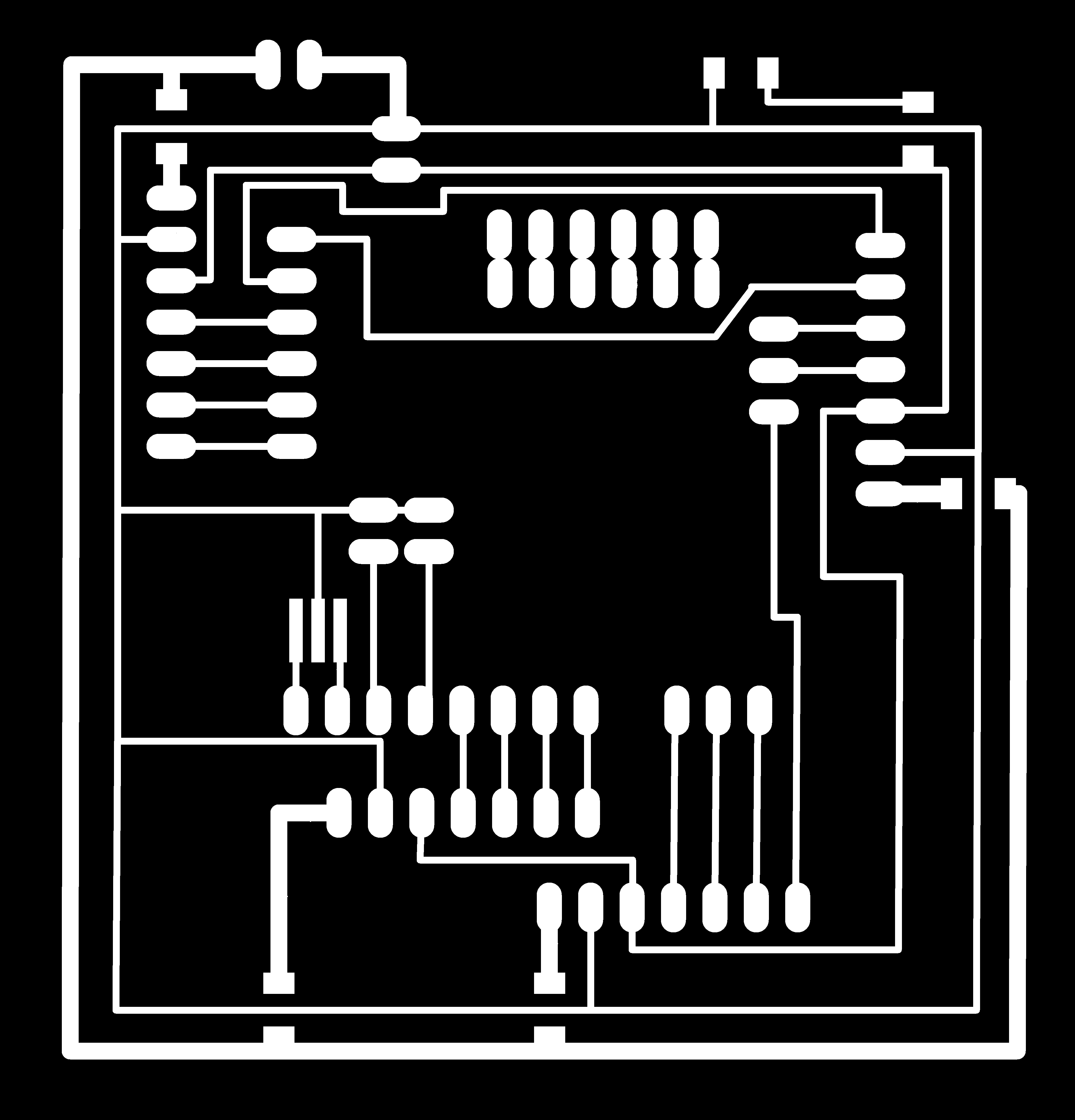
Trace file of the sheild board
Cut file of the sheild board
Schematic design file
Board design file
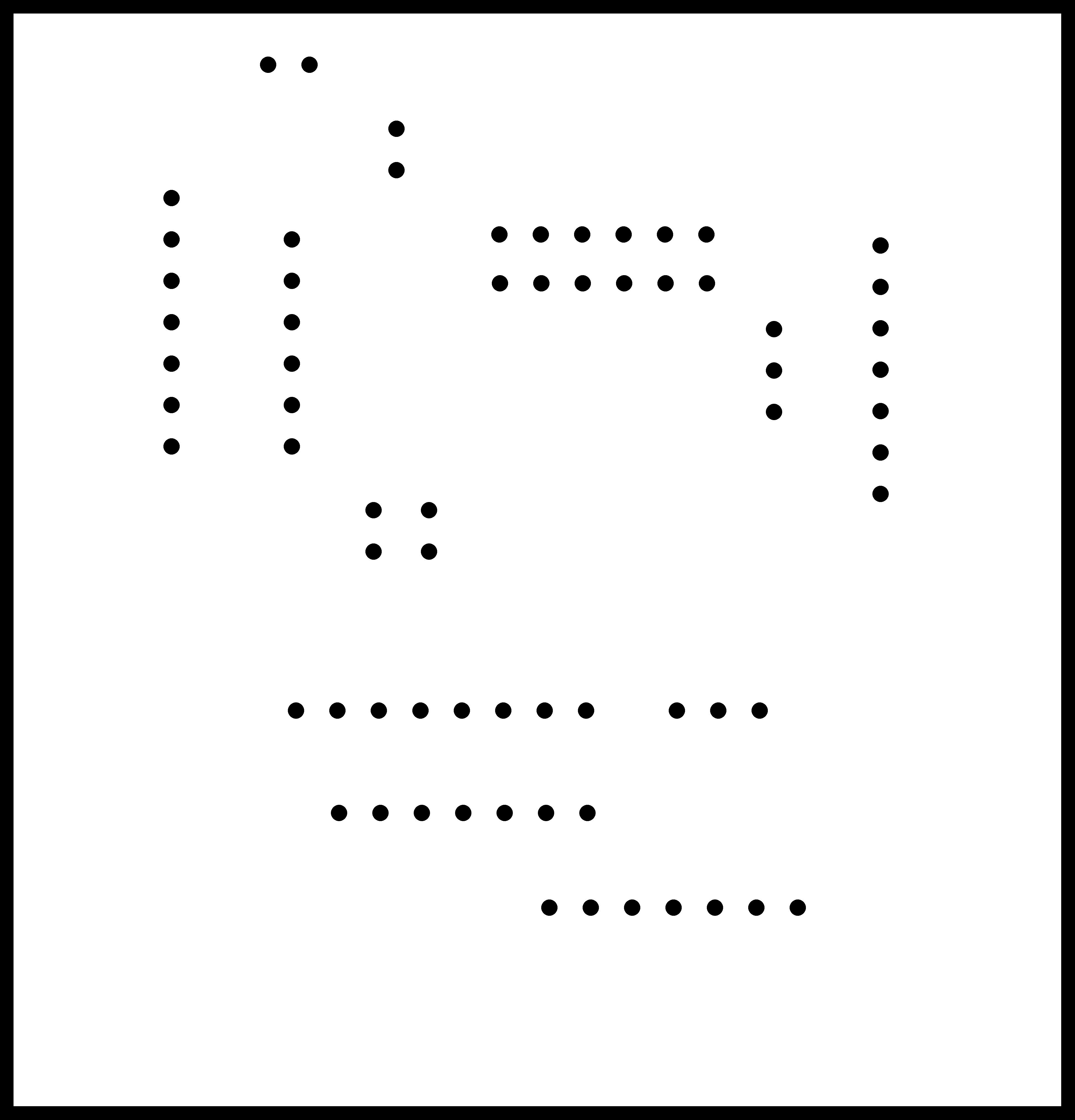
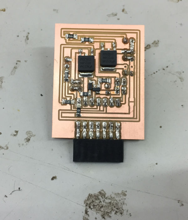
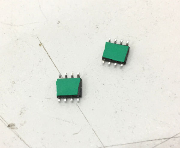
g3. The stepper control board
Finally i am making the stepper control boards. These boards basicaly have two H-bridge A4953 ic with necessory filtering
capacitors. The datasheet asks for 50+ volt ceramic capacitor but i could'nt find them locally so i had to substitute with 25v capacitors.
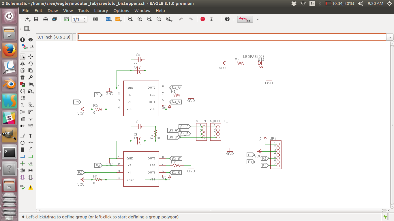
schematic diagram
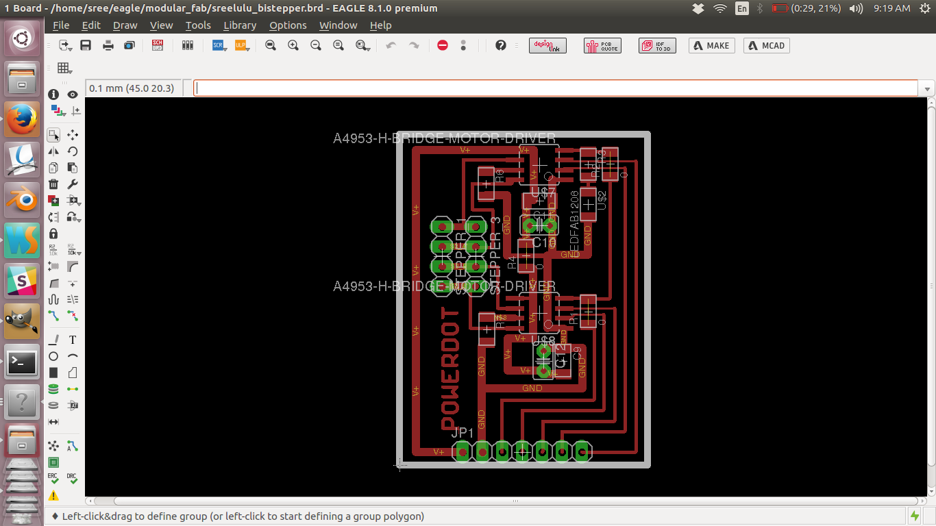
board
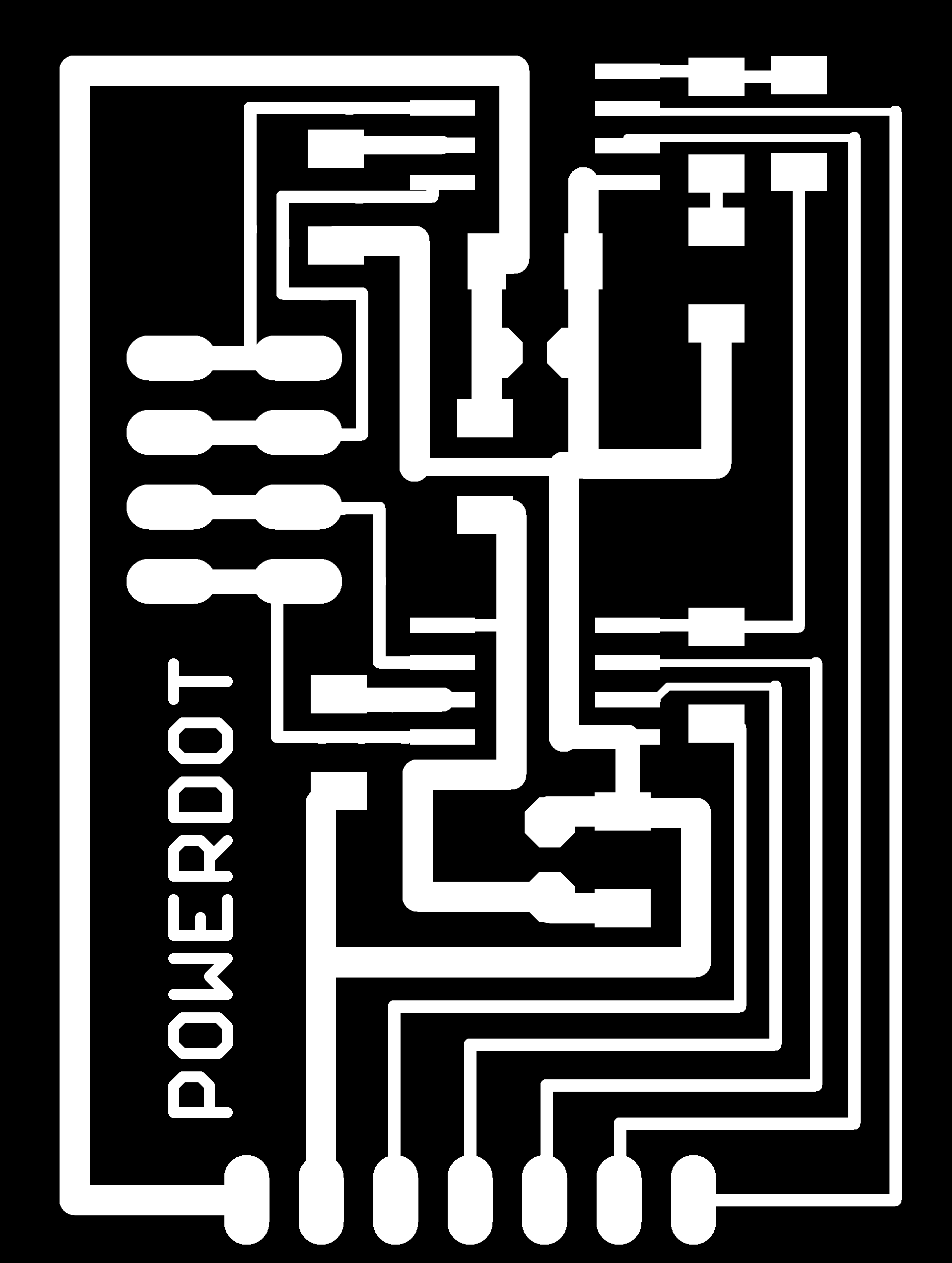
Trace file of the stepper control board
Cut file of the stepper control board
Schematic design file
Board design file
Finished board
The following are the photographs of finished board.
Finished board
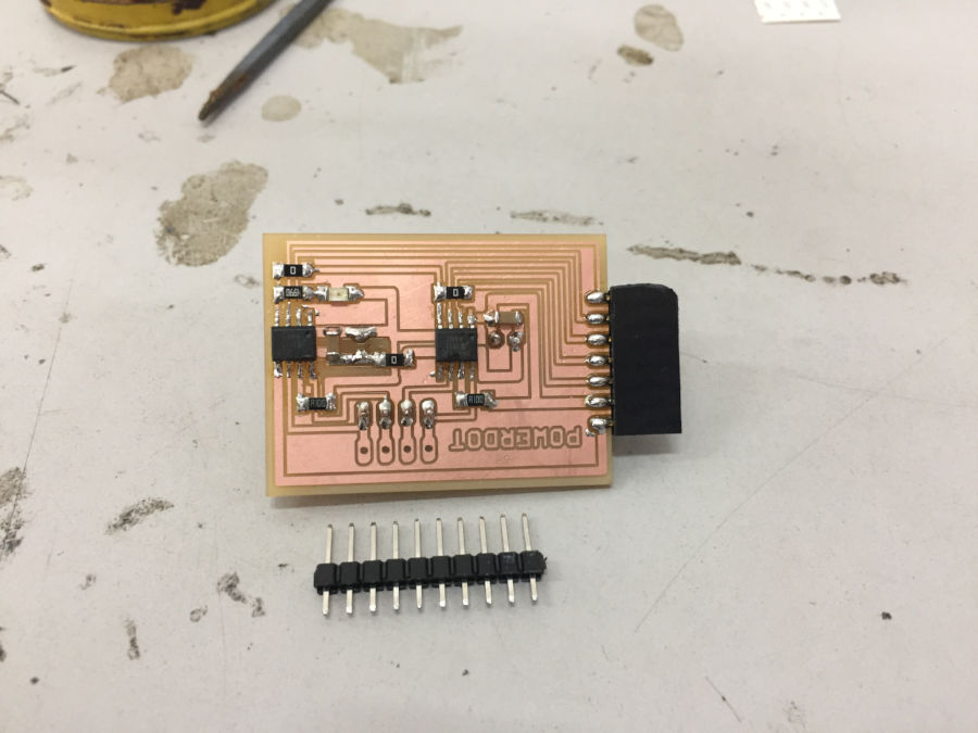
g4. The power board
Finally i am making the board to control the heater current and the stepper power. I am using N channel mosets
for this purpose. In my design i missed the requirement for the .1uF filtering to be used with the
voltage regulator, So later i had to use through hole components to compensate. This modification is not made in
the board layout file.
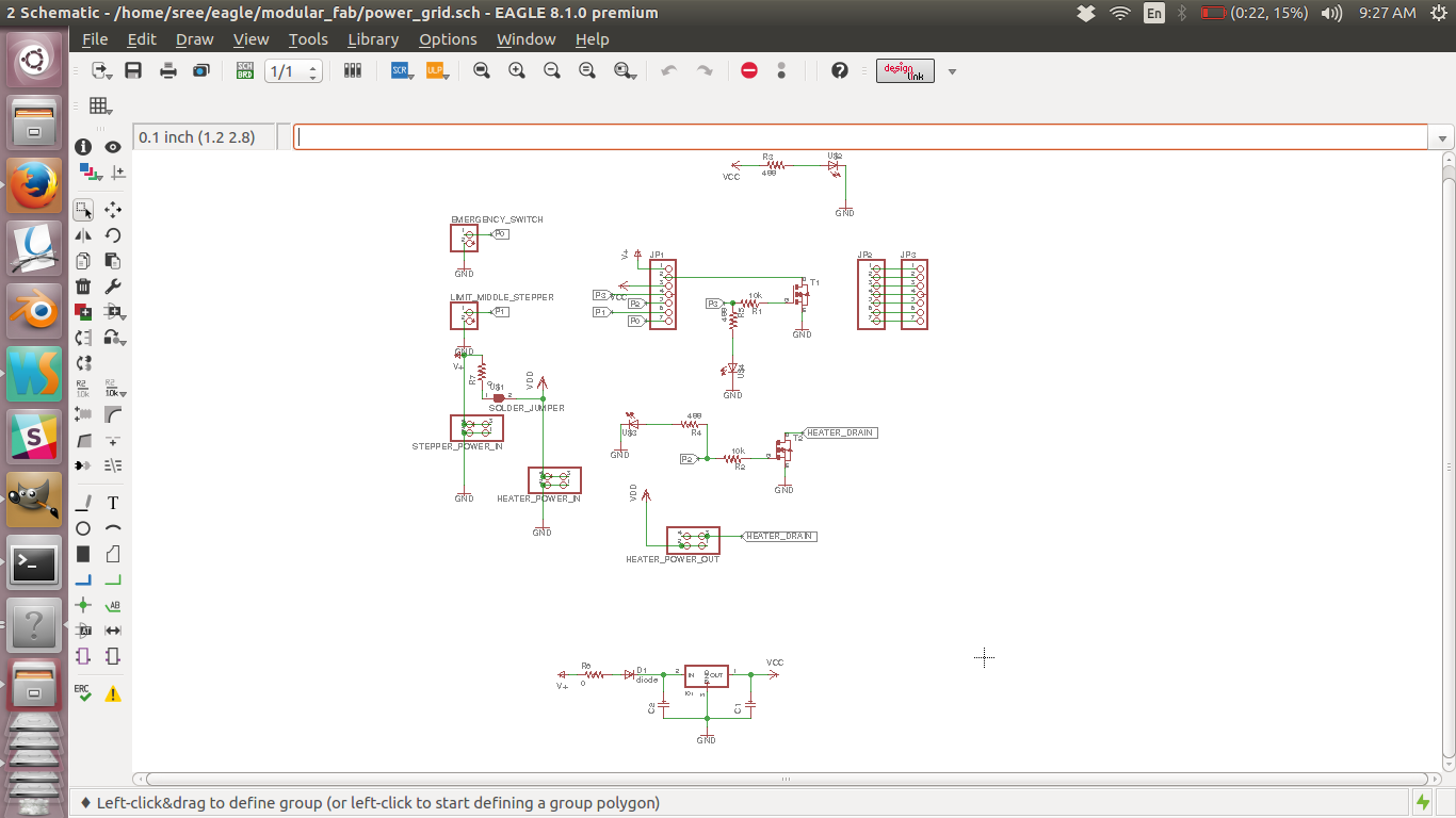
schematic diagram
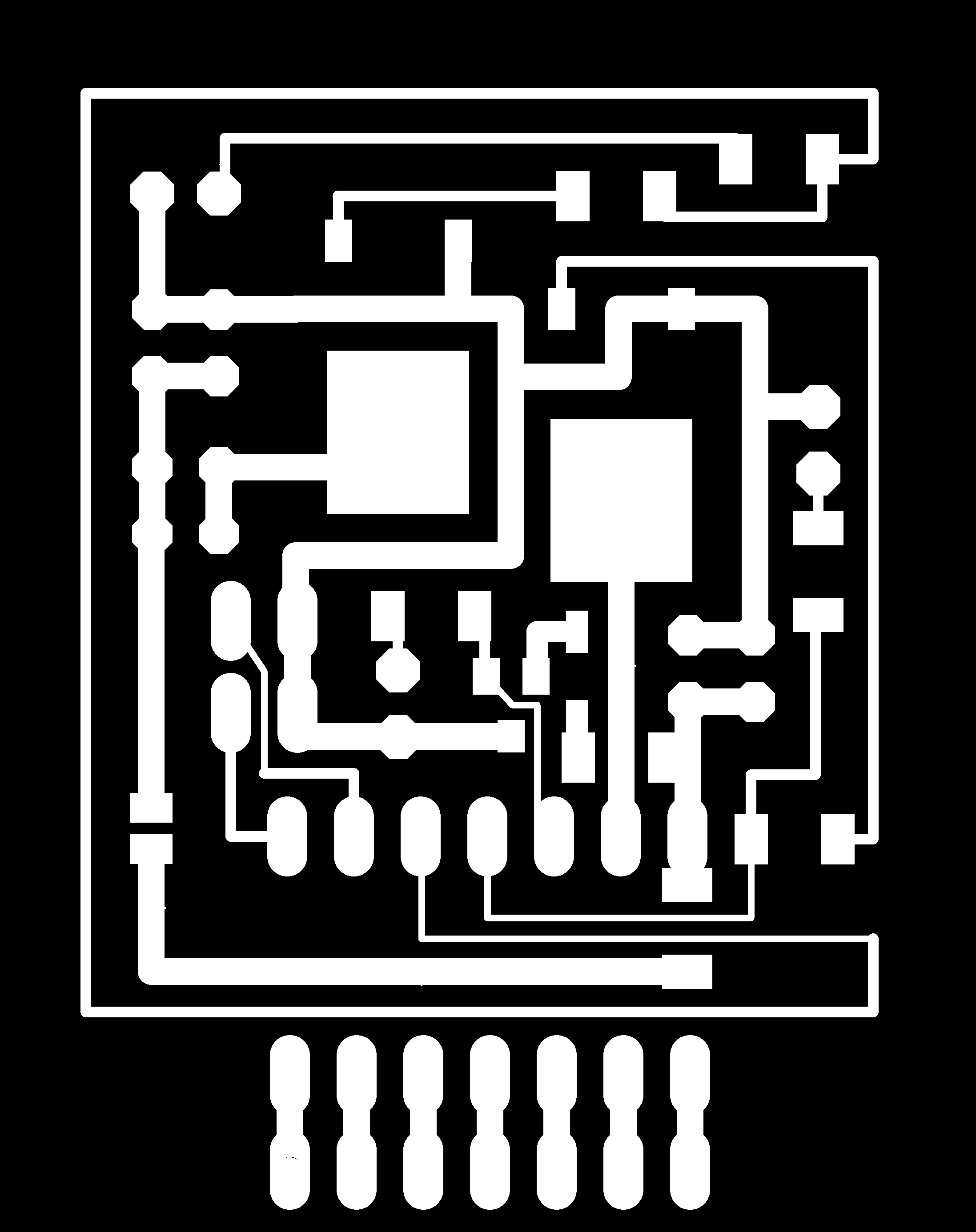
Trace file of the power board
Cut file of the power board
Schematic design file
Board design file
Finished board
The following are the photographs of finished board.
Finished board
h. connecting the boards together
As i have followed a modular design approach, connecting the boards is as easy as pluggin them togather, just make sure that
the pins are in the right order.
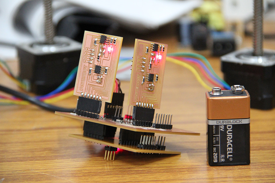
Boards wired up
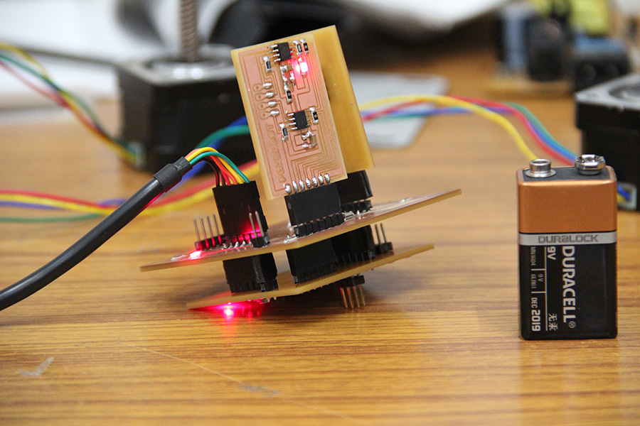
Boards wired up
i. making the limit switches
For limiting the motion of the steppers beyond a limit i added four limit switches. I scraped these switches from
old computer mouse. I removed the case of the mouse and found the pcb with the switch.
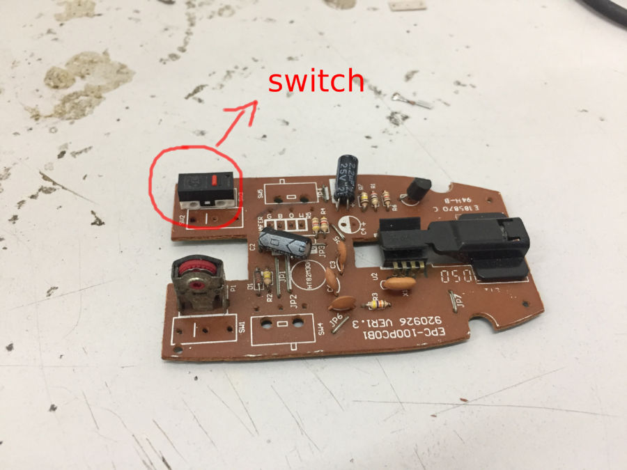
Finding the switch in old mouse
Later i desoldered and removed the switches using the de-soldering ribbon and by applying enough flux. The method is that you put enough
soldering flux on the ribbon and put it on the region to be desoldered. Now heat the ribbon with the soldering iron. The lead melts and gets
absorbed in the ribbon and we can easily pull out the component.
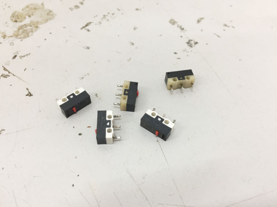
Switches removed from the pcb
Finally i started attaching wires to the switches and putting female header on the other end so that they can be pinned to my main board. I put
enough heat shrinks so that the wires don't short circuit.
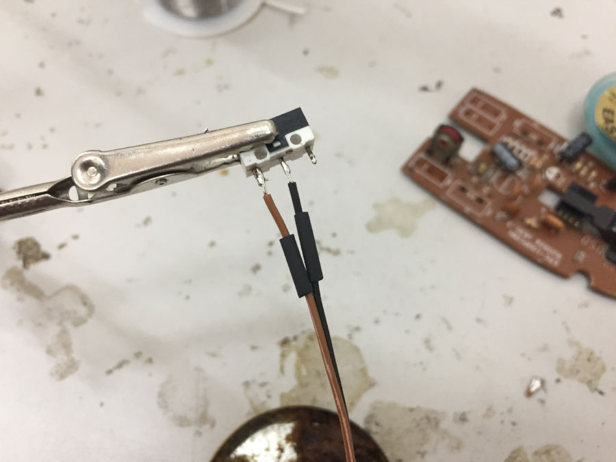
Attaching wires to switches
Now i have the switches all wired up with the headers on the other end.
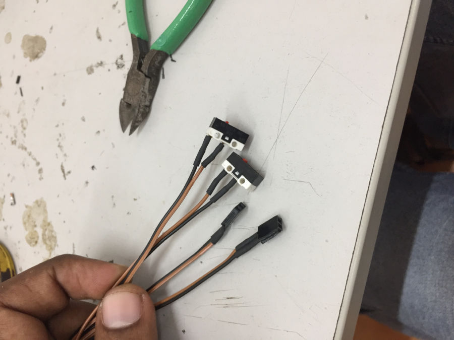
All wired up
These limit switches will inform the micro controller when each axis of the machine has reached its zero position. This info
will allow the microcontroller to limit the axix from moving beyond the allowed limit. I have already kept make headers on my
sheild board to connect limit switches.
j. time to code
Controlling a single stepper is easy and is well documented, but controlling two of them simultaniously and in sync to generate 2d shapes
is not well documented. I had to develop my own logic for this purpose. After quite a lot of trail and errors i decided to go with using timers.
I vary the stepper step speed relative to one another by setting the OCRA value. This approach has a limitation that we can control only as many
stepper as there are timers on the micro controller. In atmega328p there are 2 8 bit and 1 16 bit timer, so total of 3 stepper can be controlled.
Please view my code for more details on the implementation.
Initially my machine wont read gcode, instead i manually find the points on the shape i want my machine to draw and convert them in terms of
stepper steps and save that information in an icode file. Later when i want the machine to make the moves i send this instruction one my one.
On completing the move as per the instruction the microcontroller requests next sequence. This continues till all the movement are being executed.
The code is documented within to help you better understand it. I am reusing the USART library i make in communication week for this week.
Source code
Library code
my_stepper.c
- // Stepper Motor Demo with Accelerated Moves
- #include <avr/io.h>
- #include <util/delay.h>
- #include <avr/interrupt.h>
- #include <avr/power.h>
- #include <stdlib.h>
- #include <math.h>
- #include "../lib/USART.h"
- // set these to +/- 1 for half-stepping, +/- 2 for full-stepping
- #define FORWARD 2
- #define BACKWARD -2
- #define STEPS_PER_TURN 192
- // pin definitions; change this if you are changing the pins for output
- //stepper 1
- #define A (1 << PB0)
- #define A1 (1 << PB1)
- #define B (1 << PB2)
- #define B1 (1 << PB3)
- //stepper 2
- #define C (1 << PC0)
- #define C1 (1 << PC1)
- #define D (1 << PC2)
- #define D1 (1 << PC3)
- //stepper power
- #define POWER_PIN (1 << PD3)
- #define UNINITIALIZED 0
- #define RECEIVE 1
- #define OPERATE 2
- // global Variables
- const uint8_t motorPhasesX[] = {
- A | B, // full
- A, // hall
- A | B1, // full
- B1, // half
- A1 | B1, // etc.
- A1,
- A1 | B,
- B
- };
- const uint8_t motorPhasesY[] = {
- C | D, // full
- C, // half
- C | D1, // full
- D1, // half
- C1 | D1, // etc.
- C1,
- C1 | D,
- D
- };
- // determines freequency; this is the value set in the OCR0A
- volatile static uint8_t MAX_DELAY_X;
- //volatile static uint8_t MAX_DELAY_Y;
- volatile uint8_t stepPhaseX = 0;
- volatile int8_t directionX = FORWARD;
- volatile uint16_t stepCounterX = 0;
- volatile static int stepsToMoveX;
- volatile uint8_t stepPhaseY = 0;
- volatile int8_t directionY = FORWARD;
- volatile uint16_t stepCounterY = 0;
- volatile static int stepsToMoveY;
- static volatile unsigned char data;
- volatile char command[100];
- volatile unsigned char commandLength = 0;
- volatile unsigned char state = UNINITIALIZED;
- void initTimer(void) {
- //timer0 init
- TCCR0A |= (1 << WGM01); // CTC mode
- TCCR0B |= (1 << CS00) | (1 << CS01); // 64 prascaling
- //timer2 init
- TCCR2A |= (1 << WGM21); // CTC mode
- //CS bits are different for timer0 and timer2
- TCCR2B |= (1 << CS22); // 64 prascaling
- sei(); // enable global interrupts
- }
- //enable pin change interrupt on PD5;
- void initPinChangeInterrupt() {
- //pull up enable
- PORTD |= 0b00100000;
- PCICR |= 1 << PCIE2;
- PCMSK2 |= 1 << PCINT21;
- }
- //enable pin change interrupt for limit switches PB4 an PB5
- void initLimitSwitchPinChangeInterrupts() {
- //pull up enable
- PORTB |= 0b00110000;
- PCICR |= 1 << PCIE0;
- PCMSK0 |= 1 << PCINT4;
- PCMSK0 |= 1 << PCINT5;
- }
- // emergency stop on hitting limit switch
- void stop() {
- TIMSK0 &= ~(1 << OCIE0A);
- TIMSK2 &= ~(1 << OCIE2A);
- //disable stpper power
- PORTD &= ~(POWER_PIN);
- printString("Stop!!!! \n");
- }
- // interrupt handling for the button to print the current command
- ISR(PCINT2_vect){
- if(bit_is_clear(PIND, PD5)){
- printString("command :");
- // TransmitByte('\r');
- printString(command);
- }
- }
- //interrupt handling for the limit switch
- ISR(PCINT0_vect){
- if(bit_is_clear(PINB, PB4)){
- printString("LS 1 pressed \n");
- stop();
- }
- if(bit_is_clear(PINB, PB5)){
- printString("LS 2 pressed \n");
- stop();
- }
- }
- ISR(TIMER0_COMPA_vect) {
- stepPhaseX += directionX; // take step in right directionX
- stepPhaseX &= 0b00000111; // keep phase in range 0-7
- PORTB = motorPhasesX[stepPhaseX]; // write phase out to motor
- stepCounterX++; // count step taken
- }
- ISR(TIMER2_COMPA_vect) {
- stepPhaseY += directionY; // take step in right directionX
- stepPhaseY &= 0b00000111; // keep phase in range 0-7
- PORTC = motorPhasesY[stepPhaseY]; // write phase out to motor
- stepCounterY++; // count step taken
- }
- //not used
- unsigned int round_closest(unsigned int dividend, unsigned int divisor)
- {
- return (dividend + (divisor / 2)) / divisor;
- }
- void takeSteps(int stepsX, int8_t dirX, int stepsY, int8_t dirY) {
- //18-100
- MAX_DELAY_X = 80;
- //init counter to 0
- TCNT0= 0;
- TCNT2 = 0;
- directionX = dirX;
- directionY = dirY;
- stepCounterX = 0; // initialize to zero steps taken so far
- stepCounterY = 0; // initialize to zero steps taken so far
- //find the delay value for Y assuming x is 100
- float fraction = (float)stepsX / (float)stepsY;
- uint8_t yDelay = round((float )MAX_DELAY_X * fraction);
- //float to string
- // char buffer[6];
- // dtostrf(fraction, 6, 4, buffer);
- //
- // TransmitByte('\r');
- // printByte(stepsX);
- // TransmitByte('\r');
- // printByte(stepsY);
- // TransmitByte('\r');
- // printString(buffer);
- // TransmitByte('\r');
- // printByte(yDelay);
- // printString((char*)"----------\n");
- OCR0A = MAX_DELAY_X; // compare match at MAX_DELAY_X value
- OCR2A = yDelay; // compare match at MAX_DELAY_Y value
- TIMSK0 |= (1 << OCIE0A); // turn on interrupts, stepping
- TIMSK2 |= (1 << OCIE2A); // turn on interrupts, stepping
- //enable stpper power
- PORTD |= POWER_PIN;
- while (!((stepCounterX == stepsX) )) { ;
- } // wait
- TIMSK0 &= ~(1 << OCIE0A); // turn back off
- TIMSK2 &= ~(1 << OCIE2A); // turn back off
- //disable stepper power
- PORTD &= ~(POWER_PIN);
- }
- //not used
- void takeStepsInt(uint16_t howManySteps, int8_t dir) {
- directionX = dir;
- stepCounterX = 0;
- TIMSK0 |= (1 << OCIE0A);
- }
- ISR(USART_RX_vect){
- data = UDR0;
- //echo
- TransmitByte(data);
- if(data == '#'){
- state = RECEIVE;
- }
- if(data == ';' && state == RECEIVE){
- //command will be stored in the form xf00100yf00200, x for stepper, f for directionX(f, b) and number of steps
- char steps_x[6];
- char steps_y[6];
- int i;
- for(i = 0; i< 5; i++){
- steps_x[i] = command[i + 2];
- steps_y[i] = command[i + 9];
- }
- steps_x[5] = '\0';
- steps_y[5] = '\0';
- // printString(command);
- // printString((char*)"\n--> \n");
- // printString(steps_x);
- // printString((char*)"\n--> \n");
- // printString(steps_y);
- // printString((char*)"\n--> \n");
- //array to integer conversion
- stepsToMoveX = atoi(steps_x);
- stepsToMoveY = atoi(steps_y);
- if(command[1] == 'f'){
- directionX = FORWARD;
- }else{
- directionX = BACKWARD;
- }
- if(command[8] == 'f'){
- directionY = FORWARD;
- }else{
- directionY = BACKWARD;
- }
- state = OPERATE;
- }
- if(state == RECEIVE && data != '#'){
- command[commandLength] = data;
- commandLength++;
- }
- }
- void reset(void){
- state = UNINITIALIZED;
- uint8_t i;
- for(i=0; i< commandLength; i++){
- command[i] = 0;
- }
- commandLength = 0;
- //de-energize all steppers
- // PORTB = 0x00;
- // PORTC = 0x00;
- }
- int main(void) {
- //clock_prescale_set(clock_div_1); // CPU clock 8 MHz
- _delay_ms(1000);
- InitUART(4800, 0, 8, NONE, 1, TRUE);
- initTimer();
- initPinChangeInterrupt();
- initLimitSwitchPinChangeInterrupts();
- DDRB = A | A1 | B | B1 ;
- DDRC = C | C1 | D | D1 ;
- DDRD = POWER_PIN;
- takeSteps(100, FORWARD, 200, BACKWARD);
- // takeSteps(300, BACKWARD, 400, FORWARD);
- // takeSteps(100, FORWARD, 100, BACKWARD);
- // takeSteps(200, BACKWARD, 400, FORWARD);
- while (1) {
- if(state == OPERATE){
- takeSteps(stepsToMoveX, directionX, stepsToMoveY, directionY);
- reset();
- TransmitByte('n');
- }
- // TransmitByte('m');
- // _delay_ms(500);
- }
- return 0;
- }
The file encoding the movements: move_xy_shape.icode
- #xf00500yb00500;
- #xf00500yf00500;
- #xf00500yb00500;
- #xf00500yf00500;
- #xf00500yb00500;
- #xf00500yf00500;
- #xb01500yf01500;
- #xb01500yb01500;
This is how i encode the movement. Each line represents a specific move operation. Lets learn this by taking line 1 as an example.Each line starts with a hash and ends with a ';'. The x represents the x-axis stepper, f - forward, the next 5 digits represent the number of steps to take. Again y for the ystepper f for forward and then the number of steps.
The python code: autoPlay.py
- import serial
- import sys
- def sendString(string, serialPort):
- for letter in string:
- # print letter
- serialPort.write(letter)
- returnValue = serialPort.read(1)
- print returnValue
- def sendChar(char, serialPort):
- serialPort.write(char)
- returnValue = serialPort.read(1)
- print returnValue
- # commands = ['#xb00100;', '#xf00200;', '#xb00300;', '#xf00100;', '#xb00150;', '#xf00100;', '#xb00200;', '#xf00100;',
- # '#xb00250;']
- commands = open('move_xy_shape.icode').read().split("\n")
- if __name__ == "__main__":
- import time, urllib2
- ## Need to consider alternatives for Mac / Windows
- PORT = "/dev/ttyUSB0"
- BAUD = 4800
- command_count = 0
- s = serial.Serial(PORT, BAUD)
- s.flush()
- ## flush clears the buffer so that we're starting fresh
- sendString('#xf00001yb00001;', s)
- while (True):
- if (s.read(1) is 'n'):
- if(command_count == (len(commands)-1) ):
- print "ending ..."
- break
- sendString(commands[command_count], s)
- command_count += 1
This file basically reads the icode file and sends the data line by line over the serial to the microcontroller. It waits till its gets a signal back from the microcontroller saying its is done executing the previous operation to send the next line
k. the first moves
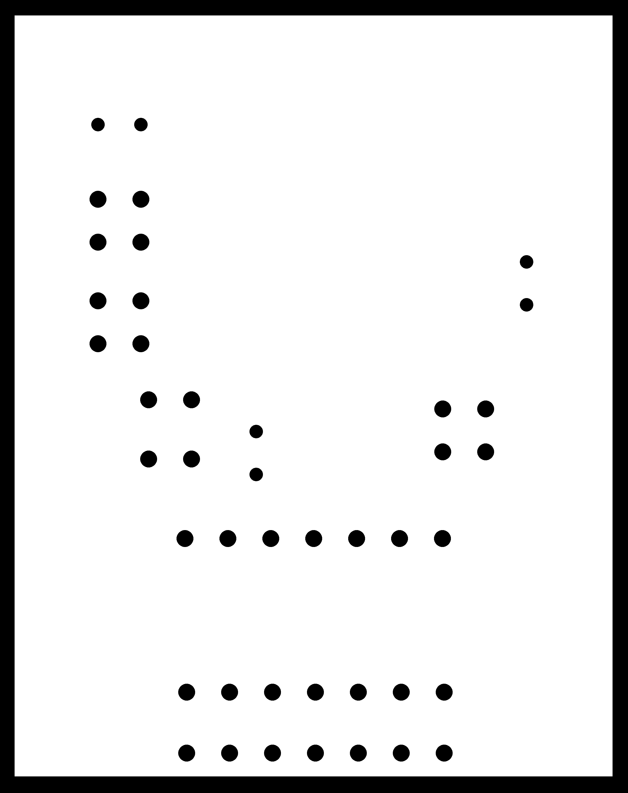
After all that hectic building and coding, its time to test the machine. First i gave the following shape to be drawn. I drew this image on a
graph paper and found the respective co ordinates, which was used to find the icode(the code listed above is for this shape). This code is send over to the
microcontroller through serial communication.
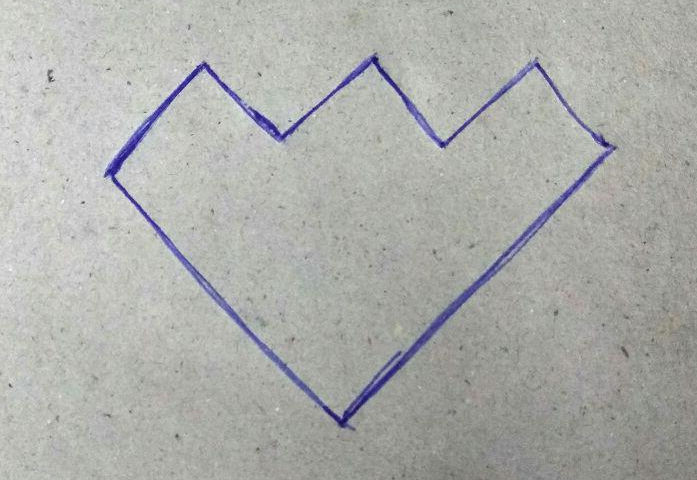
shape inpu to machine
and here goes the machine.
That is version 1 of my machine. Mission accomplished
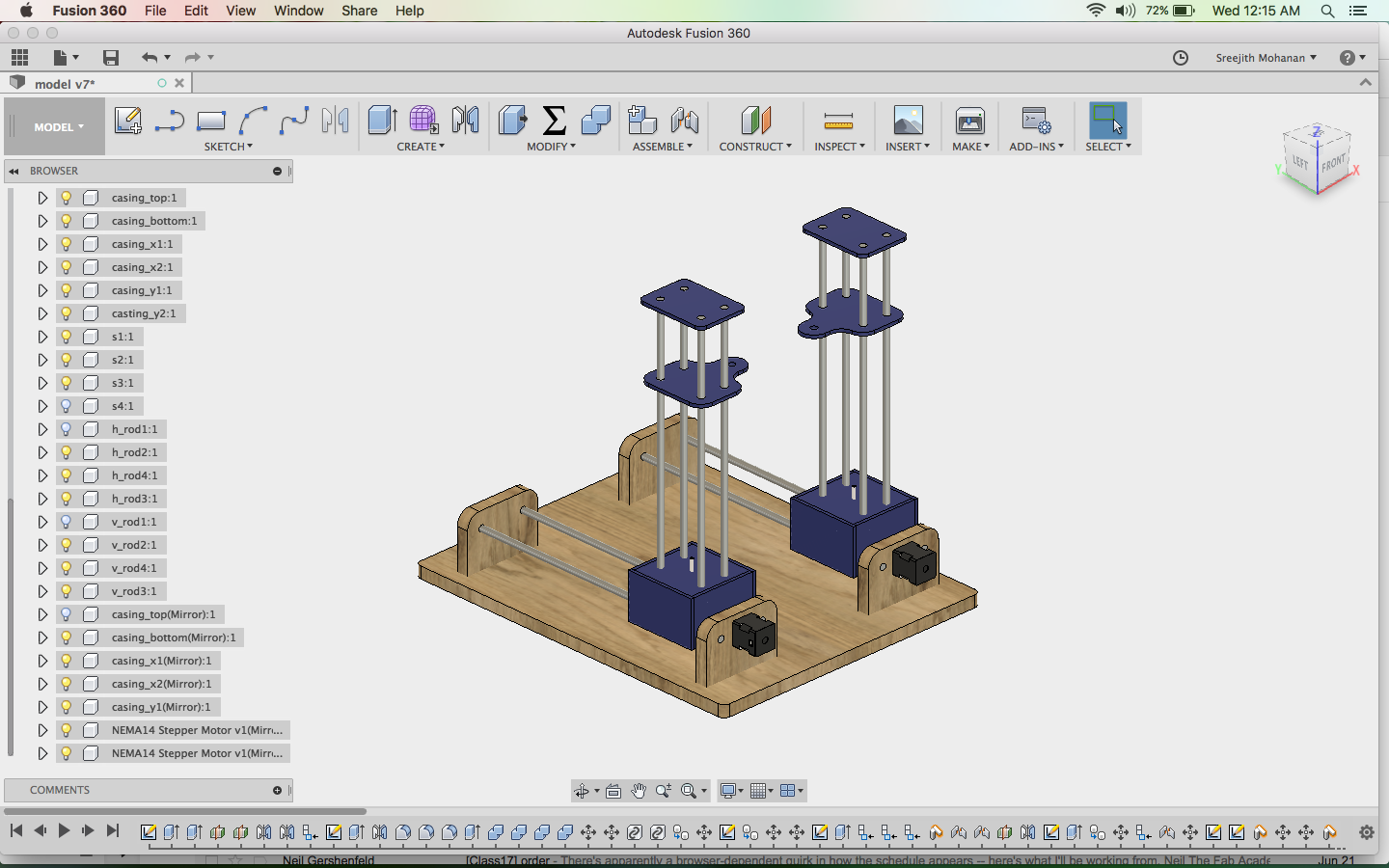
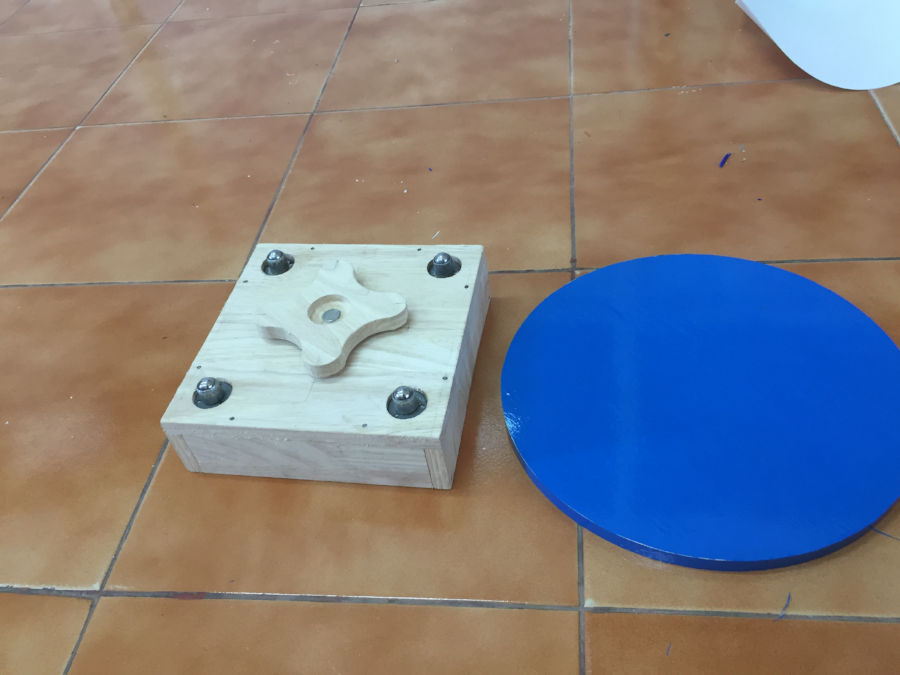
l. version 2: Including the rotating platform
Now i have make and tested the basic functionality of my foam cutter, its time to move ahead and add more functionalities as per the helical development plan. In this version i am adding the rotating platform. It is a simple platform which can be rotated by a stepper. I use a stepper from the fab inventory for this rotary axis.
l1. Doing the CAD
I made the design files in fussion. First i made the drawings
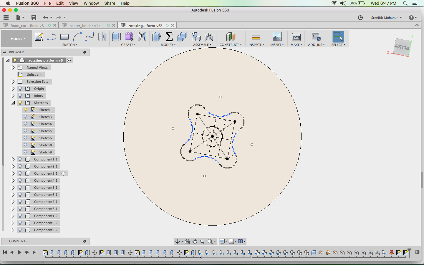
Making the drawings
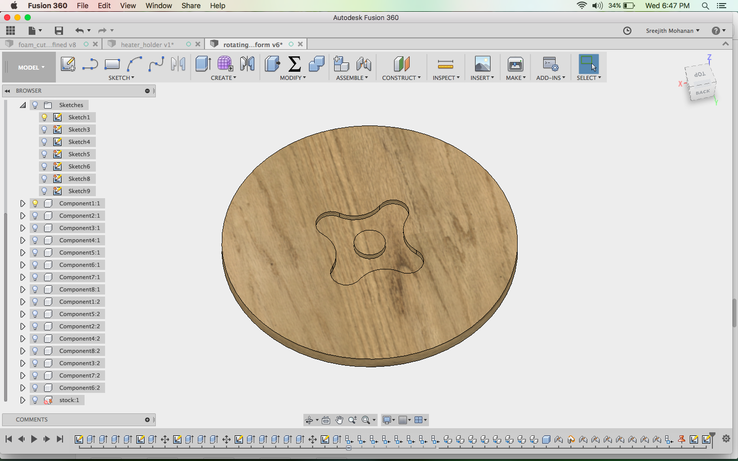
Extruding to create the shapes
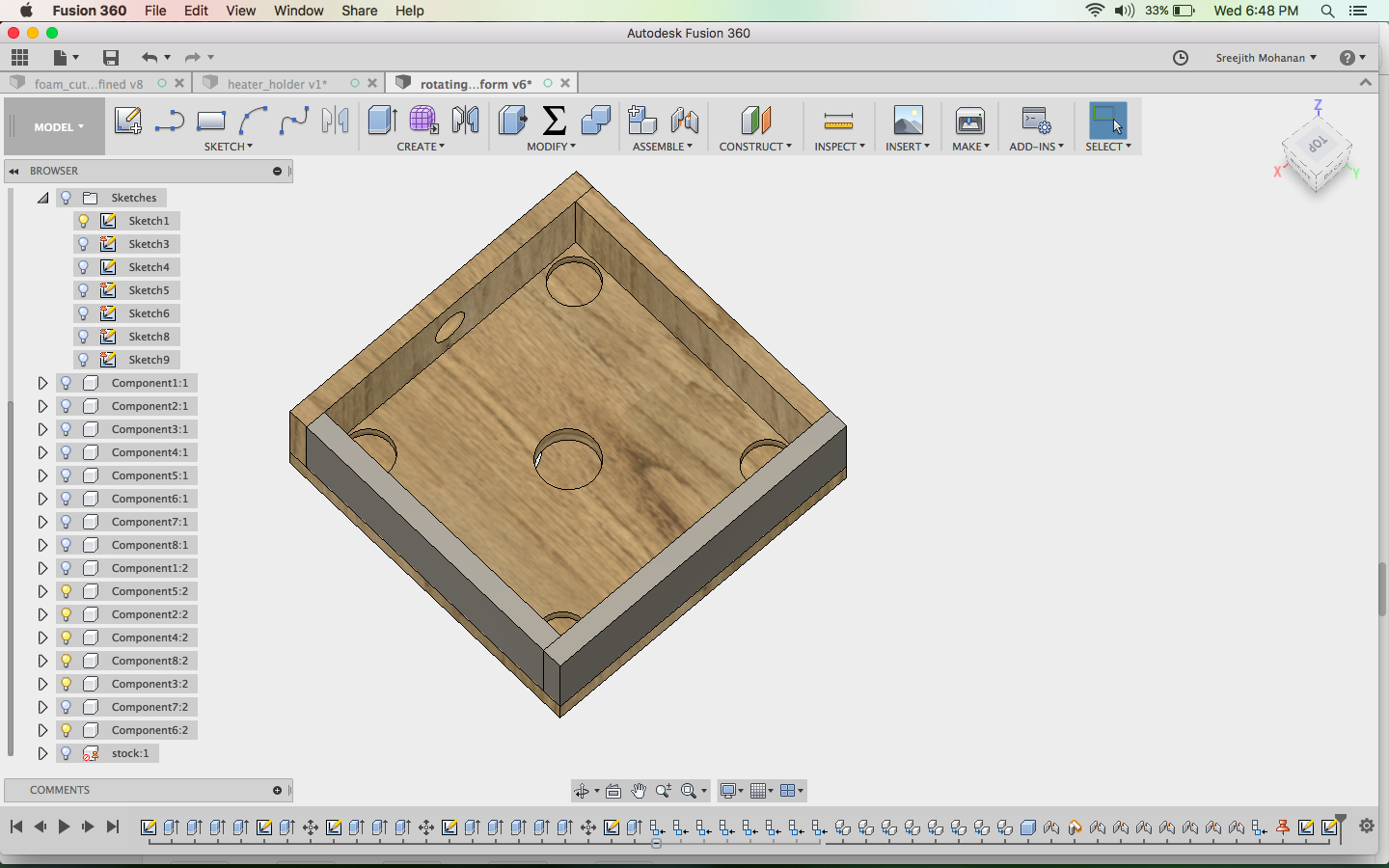
making the box
final design
The design is embedded below.
Fussion file
l2. Cutting the parts in shopbot
I used the cam tools in fussion to generate the stp files which can directly be used with the
shopbot control software. I then cut out the parts and finally assembled them. The following images show the assembly.
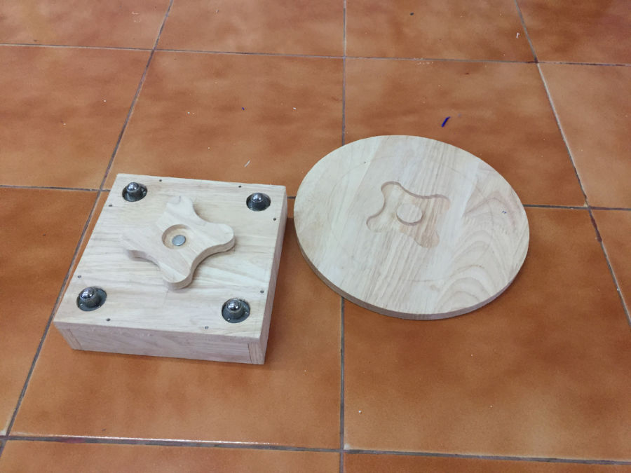
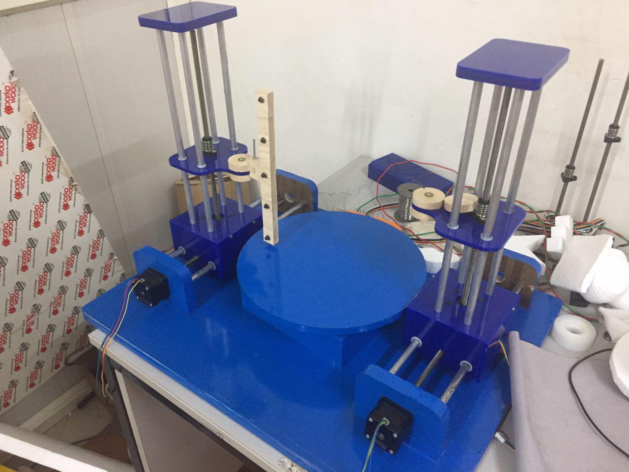
rotating platform assembly
Later i mounted this shape on the middle of my foam cutter and now i have the rotary axis.
m. making the hot wire holder
This also i did with fussion starting from the diagrams and latter extruding them.
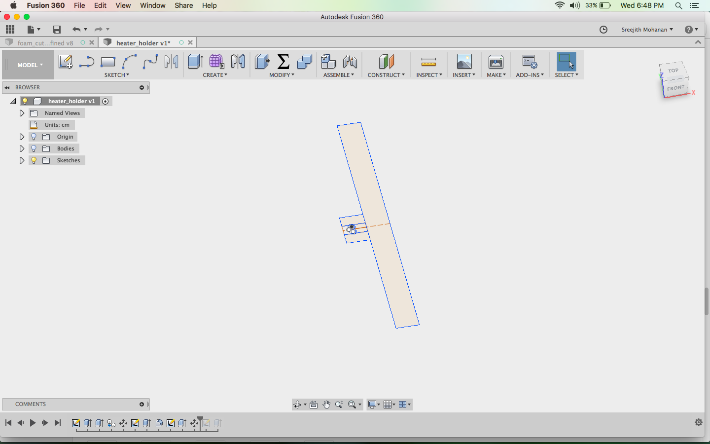
starting with drawings
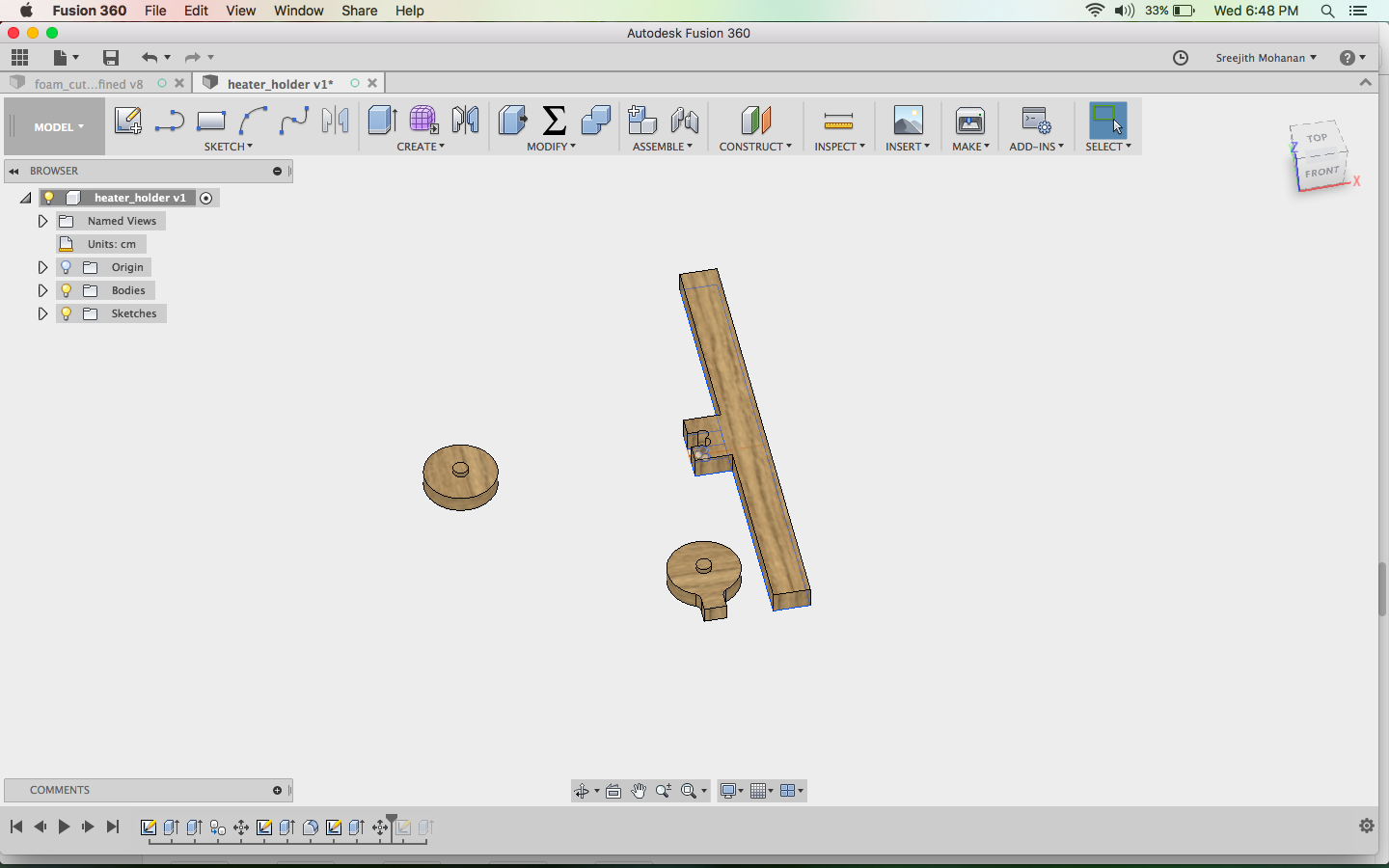
final models
Finally i cut them out and fitted to the machine.
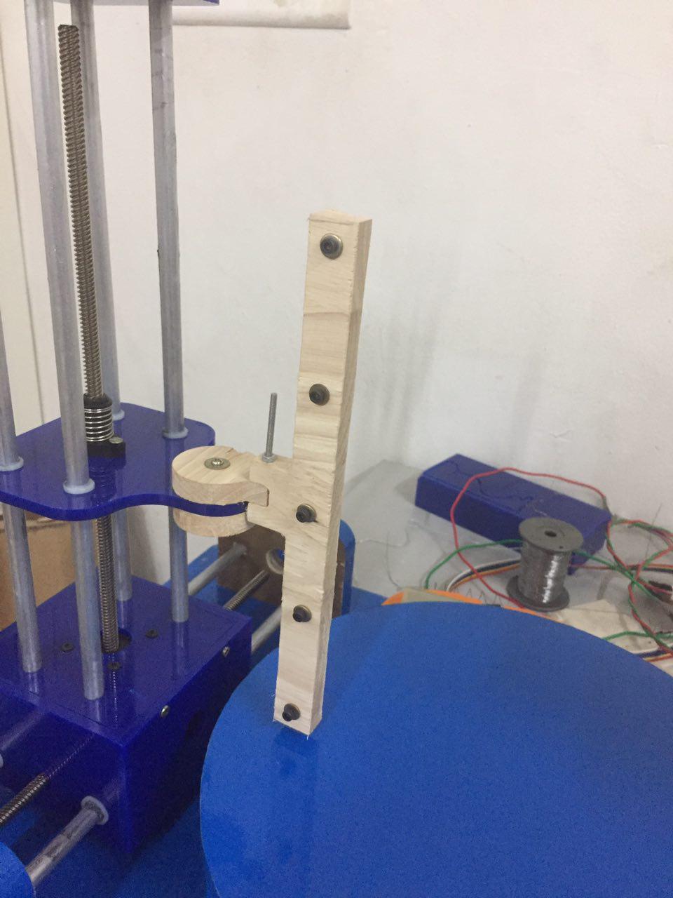
hot wire holder for lathing models
Fussion file
n. coloring the baby
Now i wanted a good looks for my machine and decided to cover it entirely in vinyl. The vinyl shapes i needed where too
bit and they could be easily hand made without using the vinyl cutter so i opted to do it manually.
Covering the rotating platform with vinyl
Covering other parts
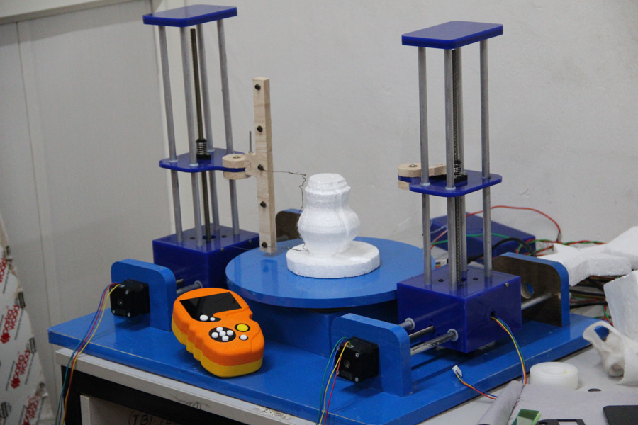
o. Final avatar
After all those hardwork here is my completed machine.
Final machine
p. Making the lathe shapes
I have developed a method to digitally make the shapes for lathe cutting.
- First make the needed shape in a cad modeling software
Making the shape - Generate the cam
Generating CAM - Make the shape in wax using the modella or shopbot. I used shopbot.
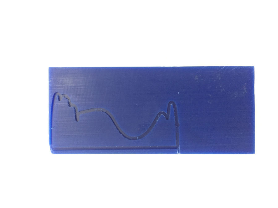
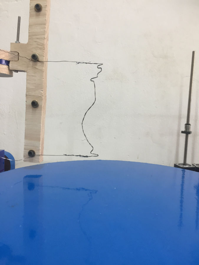
Shape cut in wax - Use this mould in the wax to transfer the lathe shape into the nichrome wire(heating wire).
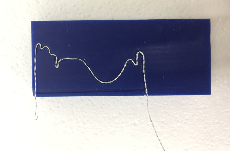
Shaping the wire - Now use this shaped nichrome wire in the machine to make the shape.
Nichrome wire fitted to the holder
q. Working the machine
The following are the videos of my machine in action.
Foam cutting
Lathe
That is version 2 of my machine. Mission accomplished
r Version 3: developing the remote controller
Now this is the third loop in the helix and i plan to make the remote controller for my machine. It is just a day left and i am not sure on how much i will be able to complete
Doing the cad
This is the step be step process of me making the controller body
Step1 : I created a drawing from the handdrawn
image presented above.
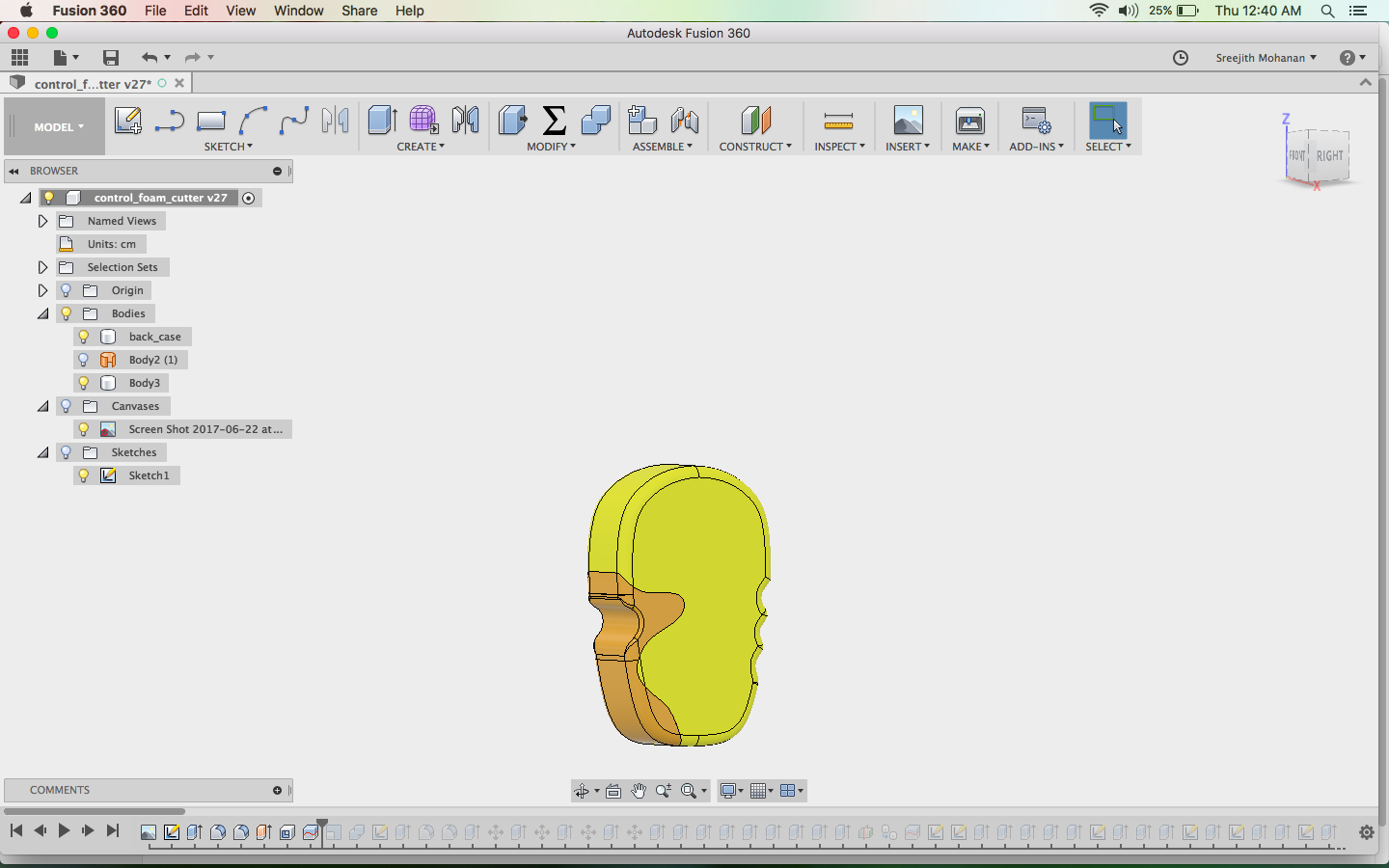
Step2: Extruded the sketches to make necessory shape
Step3: Added fillet fo make smooth edges
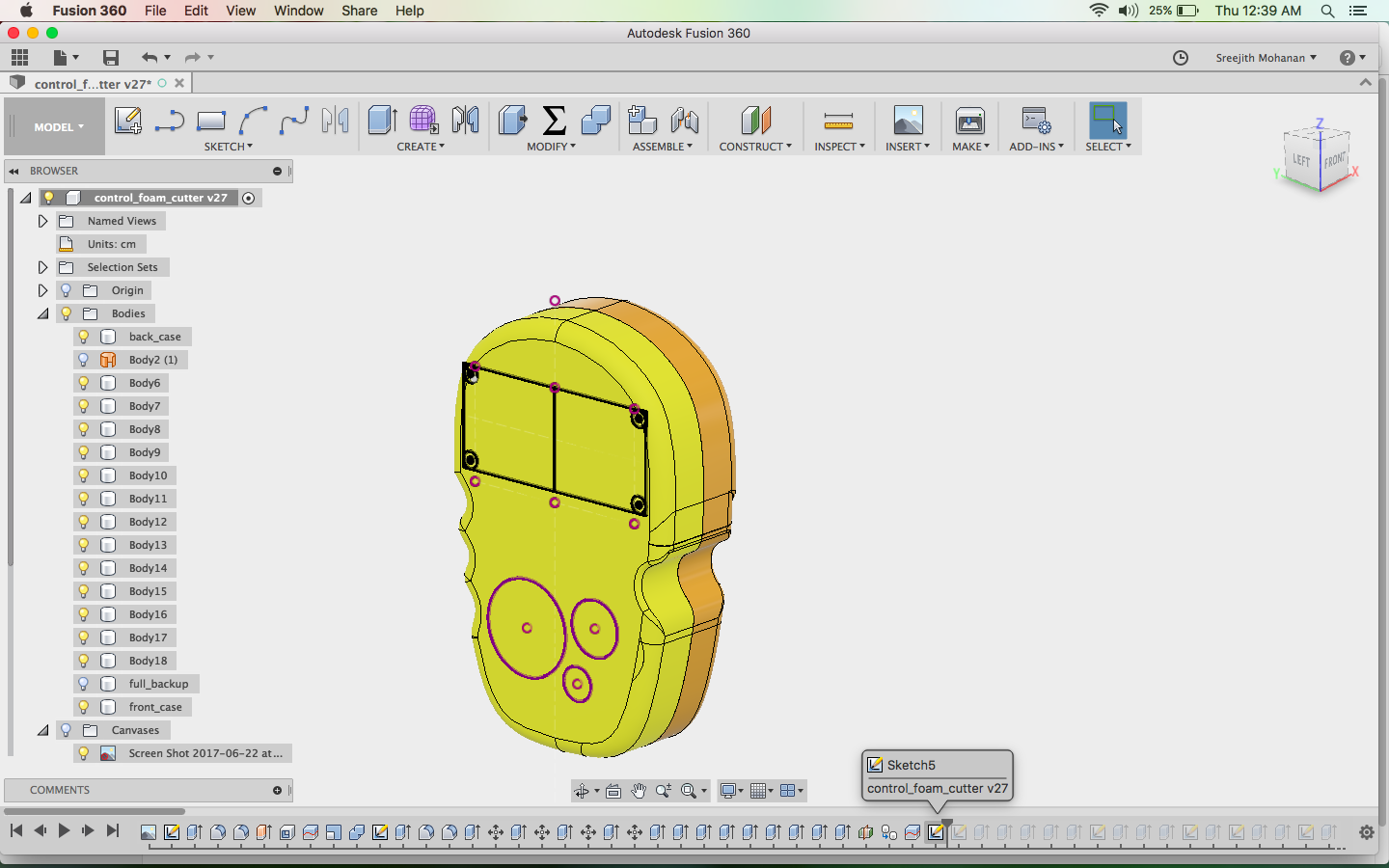
Step4: Created the profiles for the lcd and button regions
Step5: Done many iterations of push and pulls to get
the proper shape
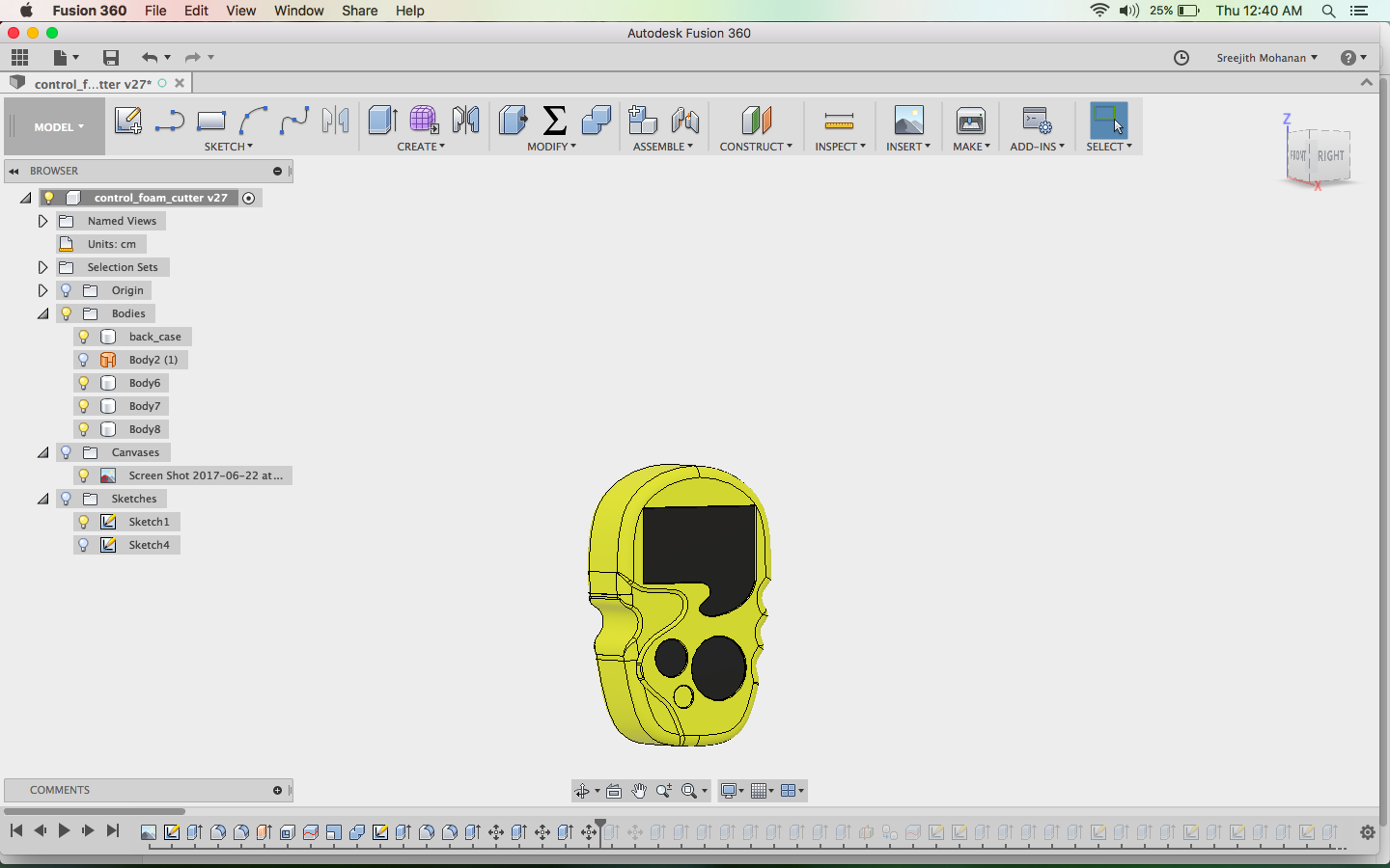
Step 6: Make the slot for acrylic parts by cutting inwards
Step 7: make the screw holders and button support structures
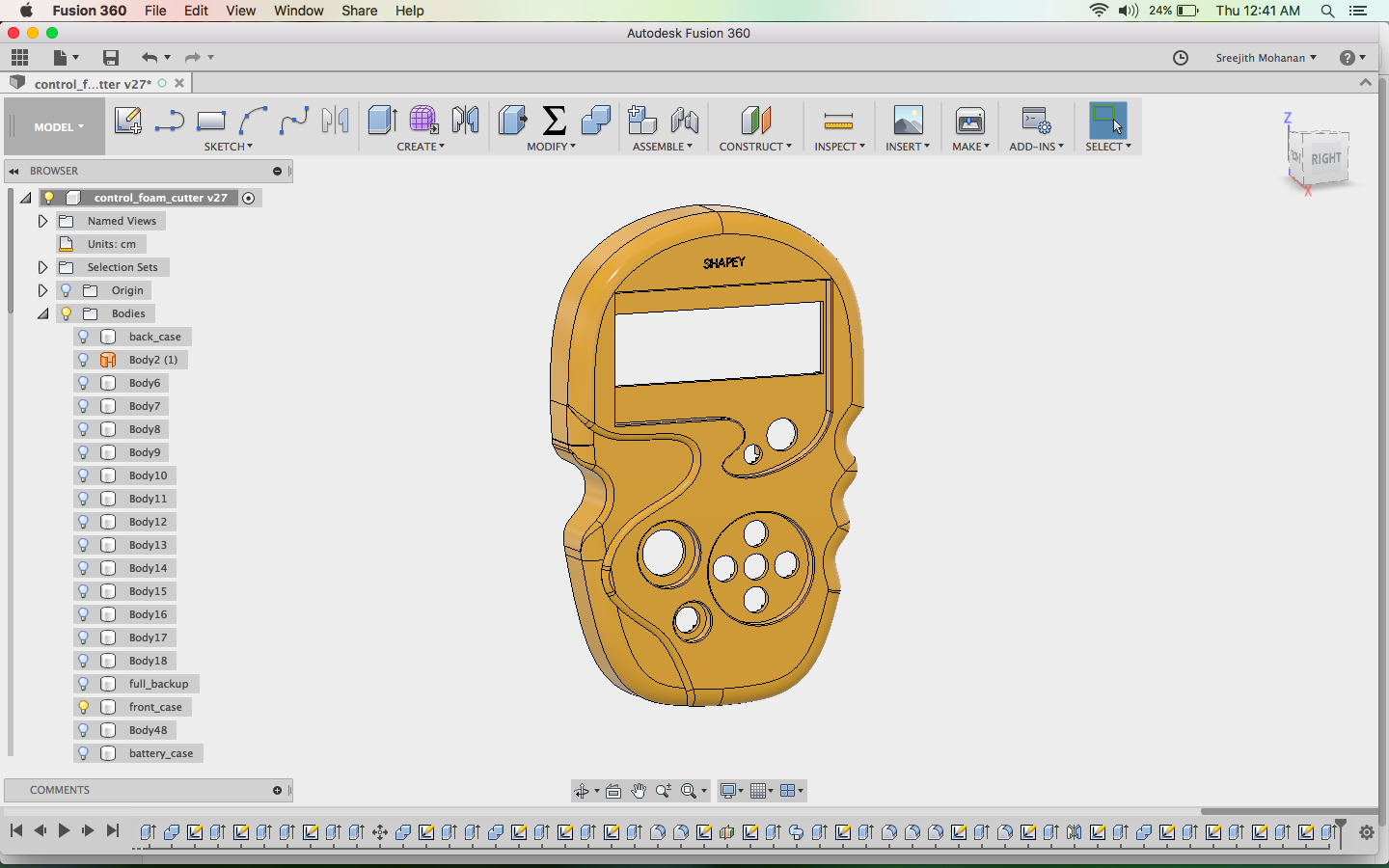
Step 8: Finally added the logo engraved
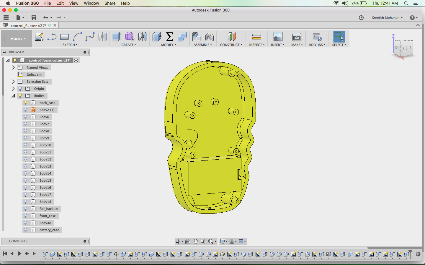
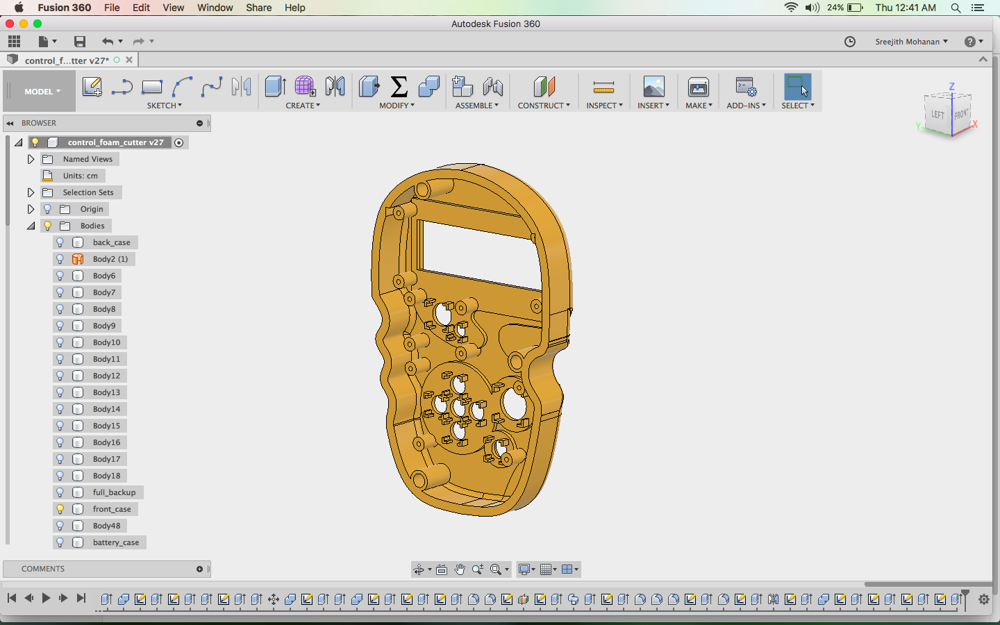
Step 9: Made a battery case in the bask part and added
the make connectors to fit the from part
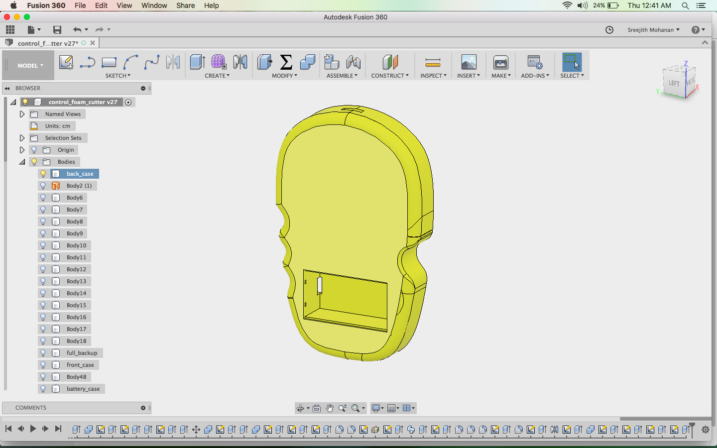
Step 10: make the holes for the battery case cover
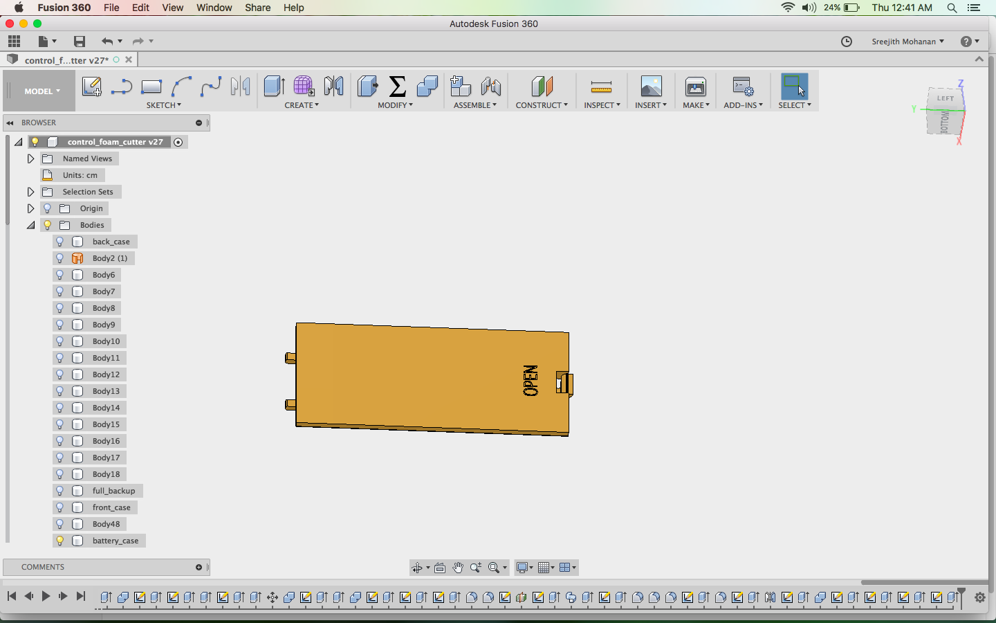
Step 11: Finally made the battery case cover
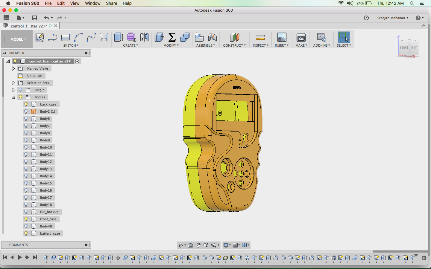
Step 12: Visual inspection for mistakes
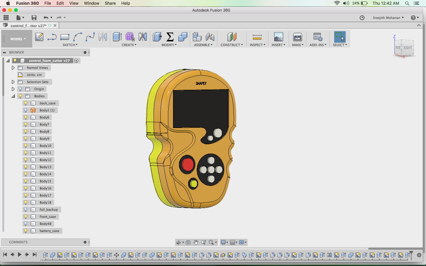
Step 13: added button and acrylic parts to get a better visualization.
Final model of the shapey control casing.
The full fussion and stl file can be downloaded from the links below
Full Fussion file
Top part STL
Bottom part STL
Battery case STL
3d printing, assembly
I generated the gcode for my models using cura and later printed the models.
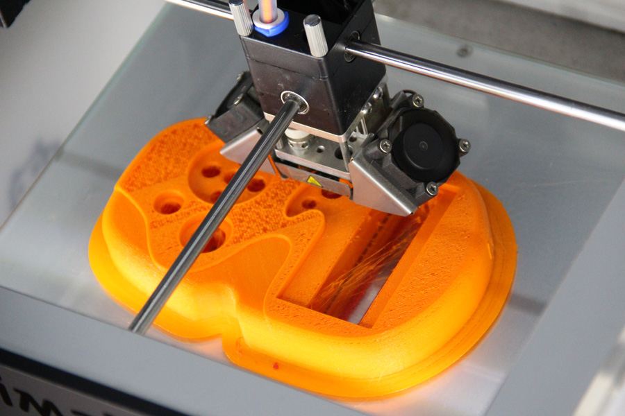
Printing the top half
Parallely i made the acrylic parts for the display part and for the place where the buttons come. Buttons where also cut out
from acrylic. I used the profiles from the fussion file i already shared to make the laser cut parts. The dxf file for the acrylic
cutting is linked below.
Acrylic cut dxf file
Fitting the acrylic cuts parts to the 3d printed parts
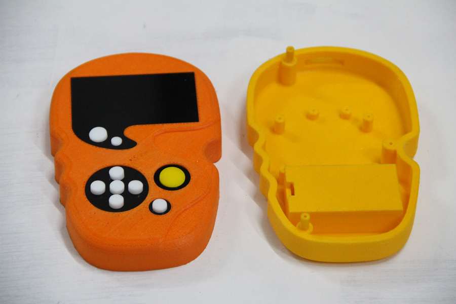
Now you have the assembled front part and the back parts.
Once i have the case ready, i started fitting the lcd display in the slow provided. The following video shows how i
fitted the LCD. Later i used screws to tighten the display in its position.
Fitting the LCD display
Similarly i fitted the SD card reader to the back casing.
Fitting the SD card reader
The other boards which go into the controller where not made due to lack of time. I used the code and board from my output week to display
text on the LCD display placed inside the casing.
Bill of material
| Sl.No | Components | Qty(Nos) |
|---|---|---|
| 1 | Atmega328P-AU | 1 |
| 2 | IC A4953 h-bridge smd | 10 |
| 3 | N channel mosfet AE51AA | 2 |
| 4 | Voltage regulator 5 v | 1 |
| 5 | Diode schottky 1A 100V | 2 |
| 6 | Capacitor- .1uF, 1206SMD | 10 |
| 7 | Capacitor- 10uF, 1206SMD | 2 |
| 8 | Capacitor-100uF, 1206SMD | 2 |
| 9 | Capacitor-100uF, through hole electrolytic | 10 |
| 10 | Crystal-20MHz SMD | 1 |
| 11 | Resistor- 1 Kohm SMD1206 | 8 |
| 12 | Resistor- 10 Kohm SMD1206 | 8 |
| 13 | Resistor- 0 ohm SMD1206 | 30 |
| 14 | LED SMD1206 | 12 |
| 15 | LED through hole | 3 |
| 16 | Push button switch SMD | 1 |
| 17 | ISP Header | 1 |
| 18 | Male -Female Header 1X20 | 3 |
| 19 | Push button switch 6mm | 1 |
| 20 | 9V Battery snap | 1 |
| 21 | 16x2 LCD Display | 1 |
| 22 | 9V Battery | 1 |
| 23 | 12v bipolar Stepper with threaded rod | 4 |
| 24 | 12V bipolar Stepper 1 | 1 |
| 25 | Anodized smoothe aluminium rods | 12 |
| 26 | Spacers | 12 |
| 27 | Nichrome wire 32 AWG | 5 m |
| 28 | Chloroform solvent for sticking acrylic | 5 m |
| 29 | Bus wires 10 wire | 5 m |
| 30 | m8 screws | 20 |
Final comments
I have made a working foam cutter and lathe machine in a stage by stage process. In the third stage i was planning to make a remote controller for my machine which will have a sd-card reader and an LCD display. The controller would be able to remotely monitor and give instructions to my machine. Due to constrain in time i was only able to make the casing of the controller and fit the LCD display to it. I am continuing the project beyond the academy to make a complete product.
Its show time
Testing the battery case; working perfectly :)
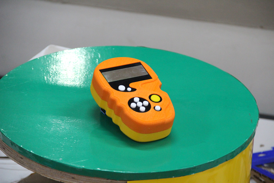
Poser
Presentation Video
s. Problems and solutions
- As i cutter my machine body in acrylic and when i was trying to make the boxes out of it, i found that laser cutting gives a small angle on the cuts. That means the side which is cut is not perpendicular. Thus its hard to stick all the parts togather to form the box. I heated a metal plate and pressed the non-perpendicular side their to make it perpendicular. Be careful no to burn the acrylic. This is not a best method but it can give you some results.
- My stepper control board had a serious error in it.The IC: A495 has a metalic base used to dissipate the heat. That plate is
also connected to the ground. In my circuit design i have traces going under the chip. This initially caused a short circuiit.
Finally i had to put some insulating material on the back of the chip to make it working.
This is not the proper way, but as i was short on time i didnt want to redesign my board and this fix worked for me.
t. Conclusion
Within the limited time i have made till the second version of my cnc machine and i am currently on the third version. It was great learning experiance so far. I was a great experiance making a machine from scrach. I like to continue developing on the machine and also make other cnc with the knowledge i have gained out of this project.

This work is licensed under a Creative Commons Attribution-NonCommercial-ShareAlike 4.0 International License.