10. OUTPUT DEVICES
Index
- Assignment
- Introduction
- Understanding How LCD works
- LCD pins
- Designing the Board
- How datasheet helped me
- Making the PCB
- Making the Connections
- Time to Code
- Final Results
- Making a board with connectors
- Results
- Problems and Solutions
- Summary
A. Assignment
- Add an output device to a microcontroller board you've designed and program it to do something.
B. Introduction
In this week we are working with output devices. I am very much interested in the LCD Display and is planning to use it for future projects, therefore i am taking this week to master the usage of LCD.
c. Understanding how LCD displays work
Understanding how the LCD works is very much essential in using and in debugging
potential
issues.
These are some of the tutorials which helped me with understanding the working of LCD, Pin
connections and
how
to program it. The following are good tutorials and i would recommend them to anyone who wants to do
LCD
programming in AVR C.
In these tutorials microcontrollers like ATmega 32/16 with 40
pins are used and as per the datasheet the registers are different for Atmega328p au which is the
one which
i have picked up for my assignment from the Fab inventory.
So the plan is to learn how to do from these tutorials, study the code and write my own for
Atmega328p also
create
a library which can be used further in other projects.
- LCD programming tutorials from Newbiehack.com
- LCD tutorial by /www.avr-tutorials.com
- Tutorial from maxembedded.com
c1. LCD pins
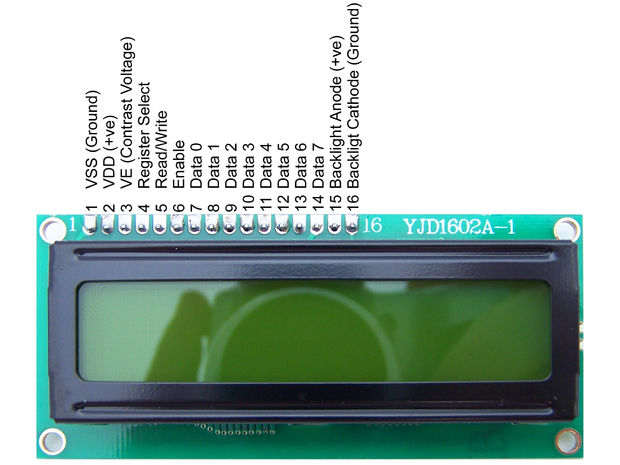
Image from instructables.com
The Lcd had 16 pins as you can see in the image above.The details of the pins are as follows.
- VSS - This is the ground pin
- VDD - This is the +5 V pin to be connected to the mains
- VE - The third pin is for contrast adjustments(VE). We connect a variable resistances output lead to this pin so that we can adjust the contrast of the LCD easily.
- Register Select - This pin is used to control the LCD such that we can provide some data to be displayed or we can send command to the LCD
- Read/Write - This pin helps us select between read and write modes of the LCD. In read mode we can read the state of the LCD if it is busy or it is ready to accept data to be displayed. In write mode we can send data to the lcd which will get displayed
- Enable - LCD is quite slow this pin needs to be toggled before every operation
- Data 0- 7 these are data bits. We can send data into the LCD through these pins.There are 8 of them for every bit togather forming a byte. The lcd works on full byte and half byte mode. In full byte mode all thse 8 pins are used to send data into the LCD in the half byte mode only the first 4 pins are used. If you are using an AVR with less pins or if you want to use minimum pins for LCD you can go with the half byte mode otherwise 8 bit mode is fine
- The last 2 pins are for backlight. The datasheet instructs a 560 ohm resister on this but something like 1K works perfectly.
d. Designing the Board
After going through the tutorials and reading the the datasheet of Atmega328p which is
the MC i
am
planning
to use for the project i realized that it will be good to have an entire port(8pins ) for the data
bits.
I found that the only port in this MC which can be used for the LCD(in 8 bit mode) is port B.
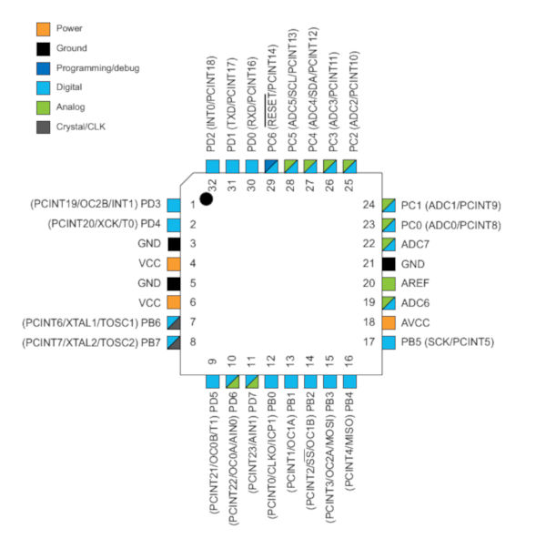
Pin diagram of Atmega328p.
Port C has only 7 pins, In port D is the RX and TX pins which i want for serial communication later
as i am
making this
pcb little bit generic so that this can be used for further experimentation and maybe for upcomming
weeks
also.
Port B also has a problem, ie,PB6 and PB7 are the pins for the external clock. So the question was
either
speed
or LCD.
Obviously i had to go for the LCD. So Port B was fixed for the data bits and i intent to put a
serial port,
a
power indicating
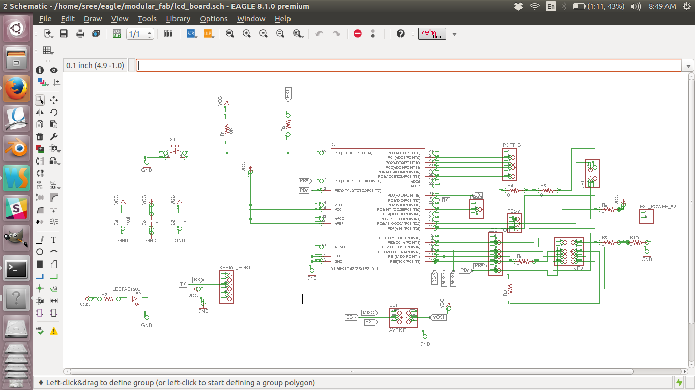
LED and a reset button in the board. I would take all the other pins through headers.The following
are the
schematic and
board images i made for my circuit in eagle.
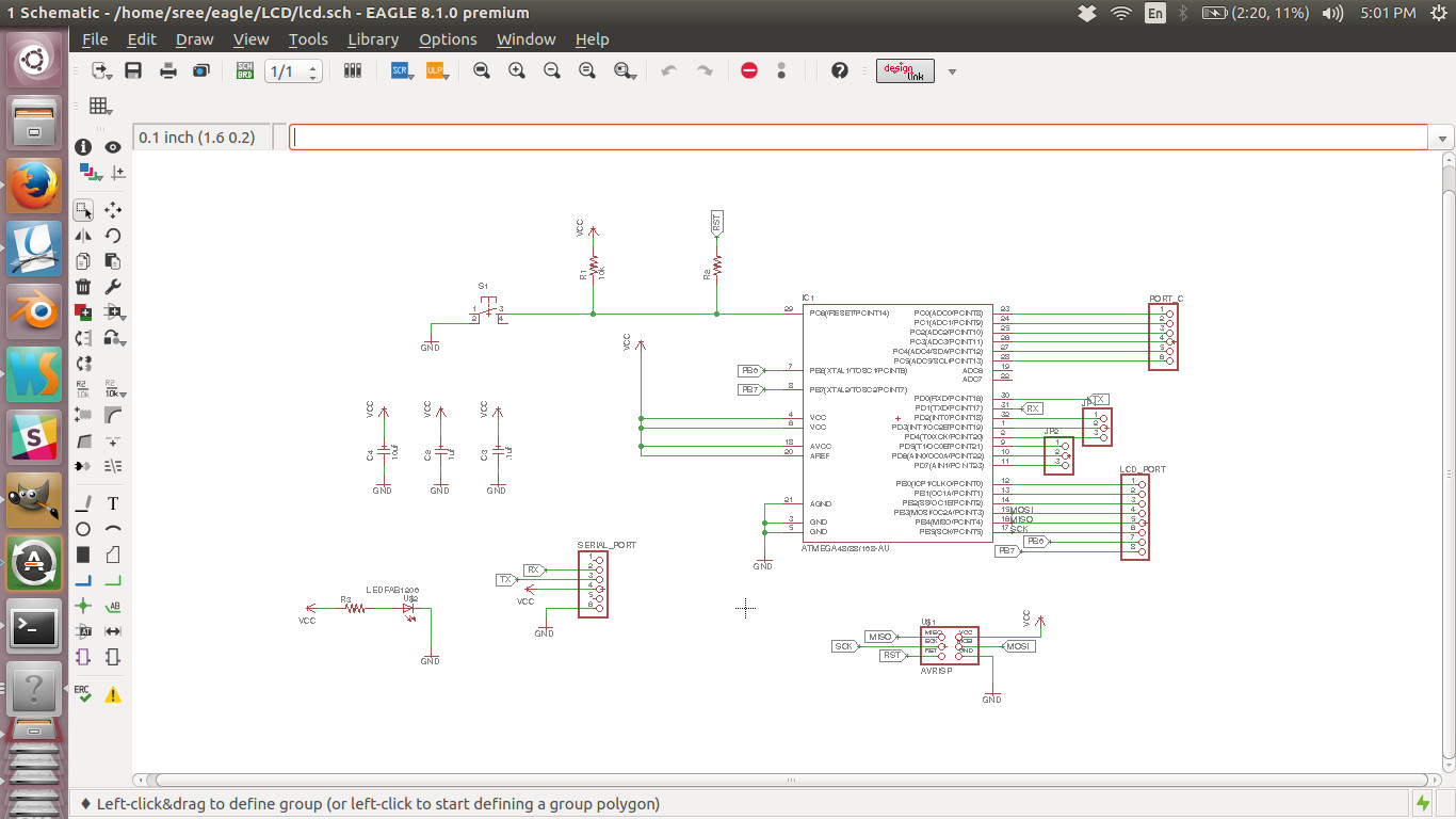
Schematic diagram
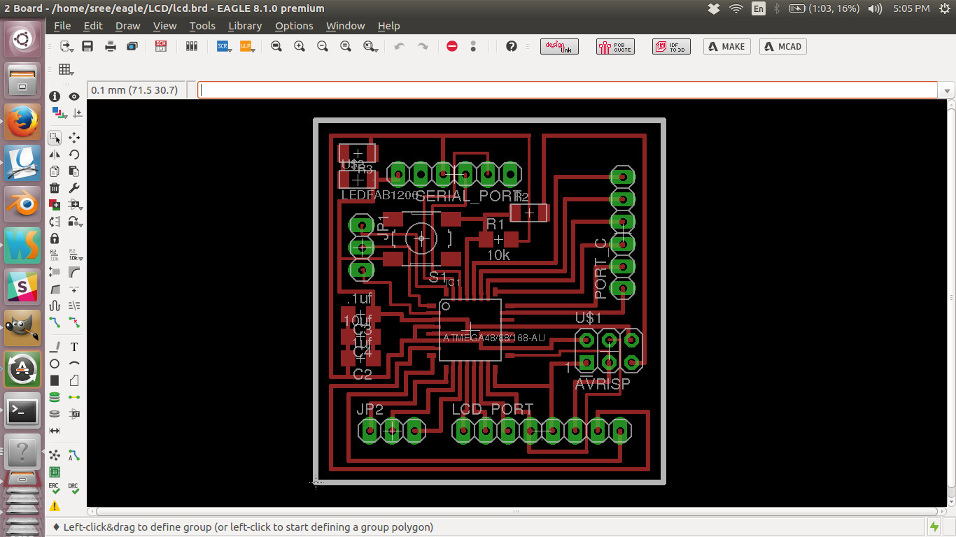
Board layout
Schematic design file
Board design file
d1. how datasheet helped me
The pin diagram in the datasheet came handy while designing the pcb. It showed me where all the pins where. I typically needed 8 pins for using the LCD in the 8 bit mode. Refering to the datasheet i could find that port b is ideal for my purpose.
e. Making the PCB
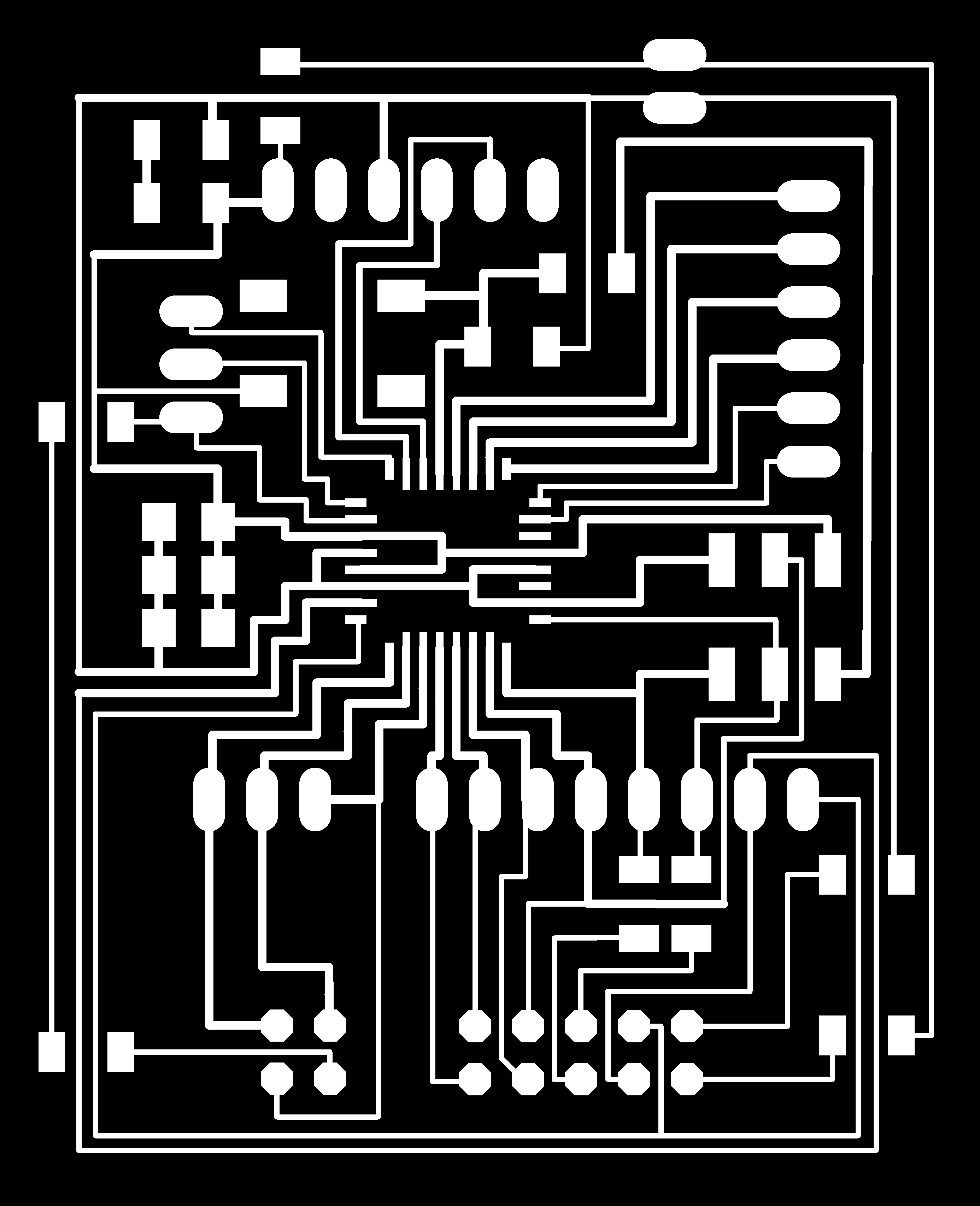
Then i created the monochrome png images for milling and cutting. Those images in full resolution
are given
below.
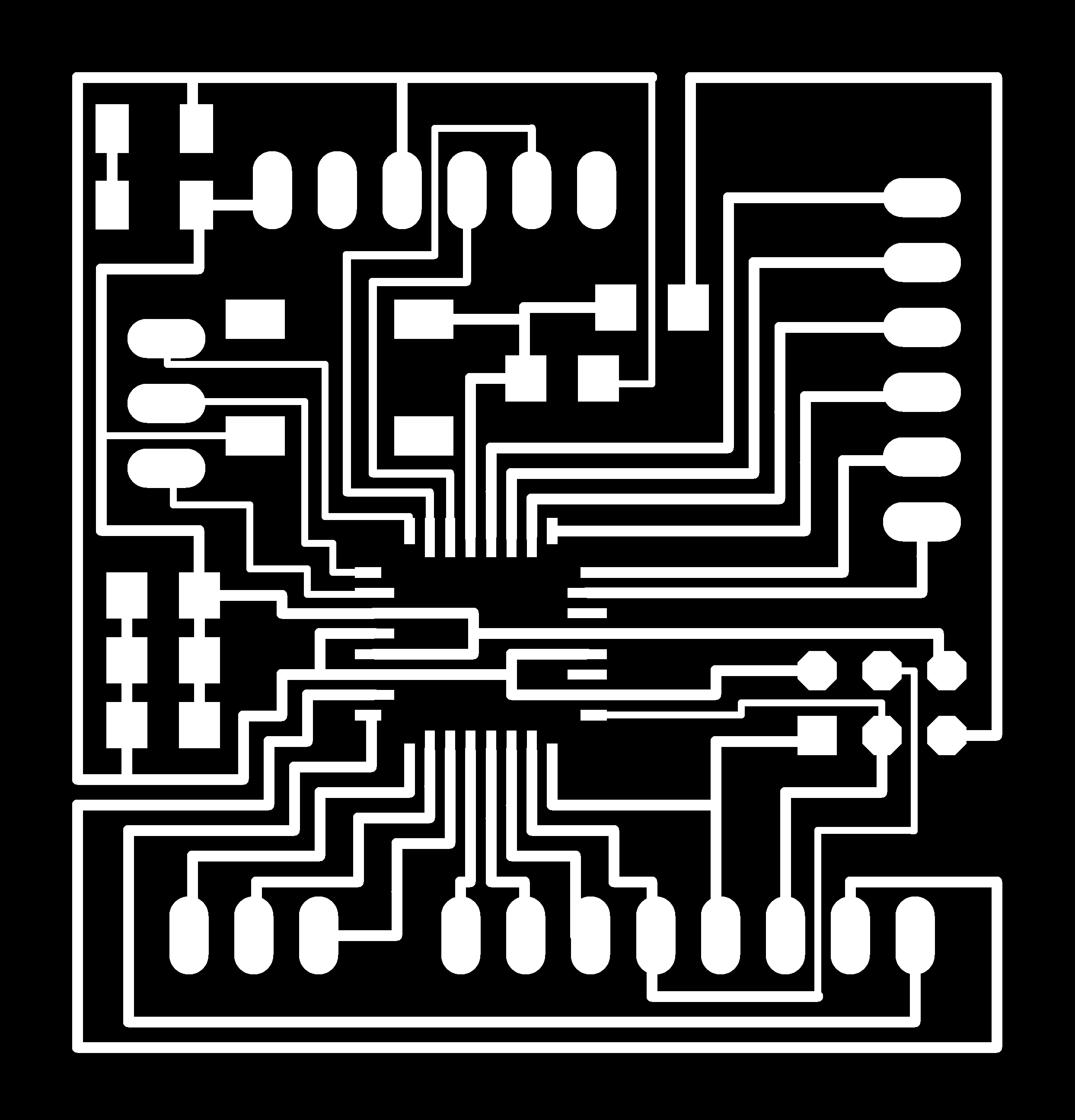
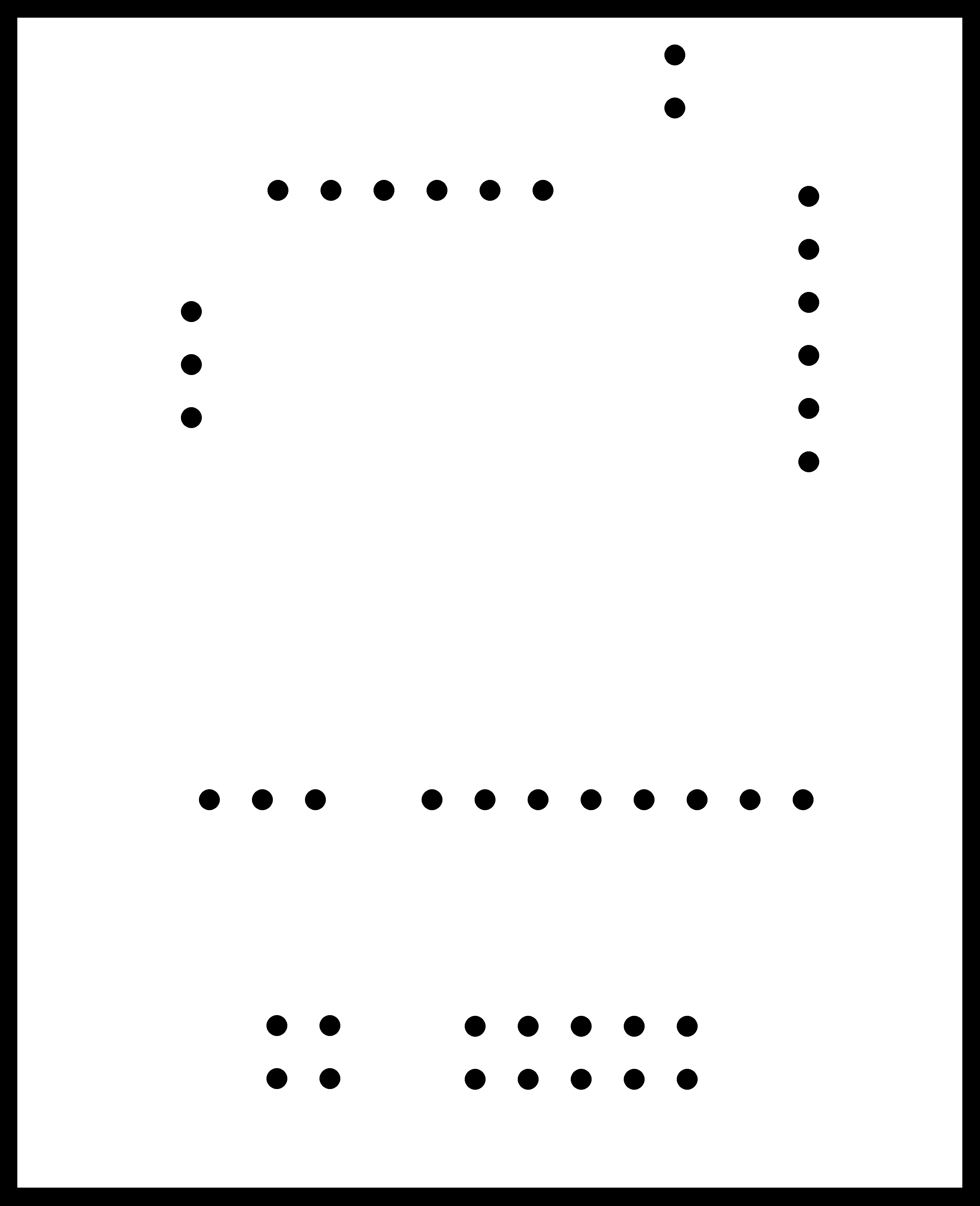
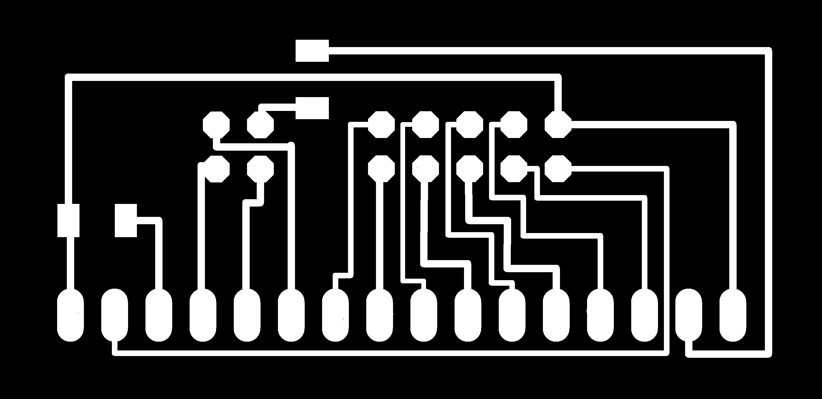
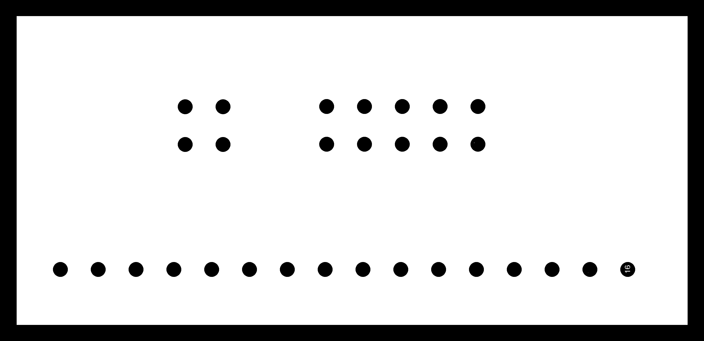
traces image
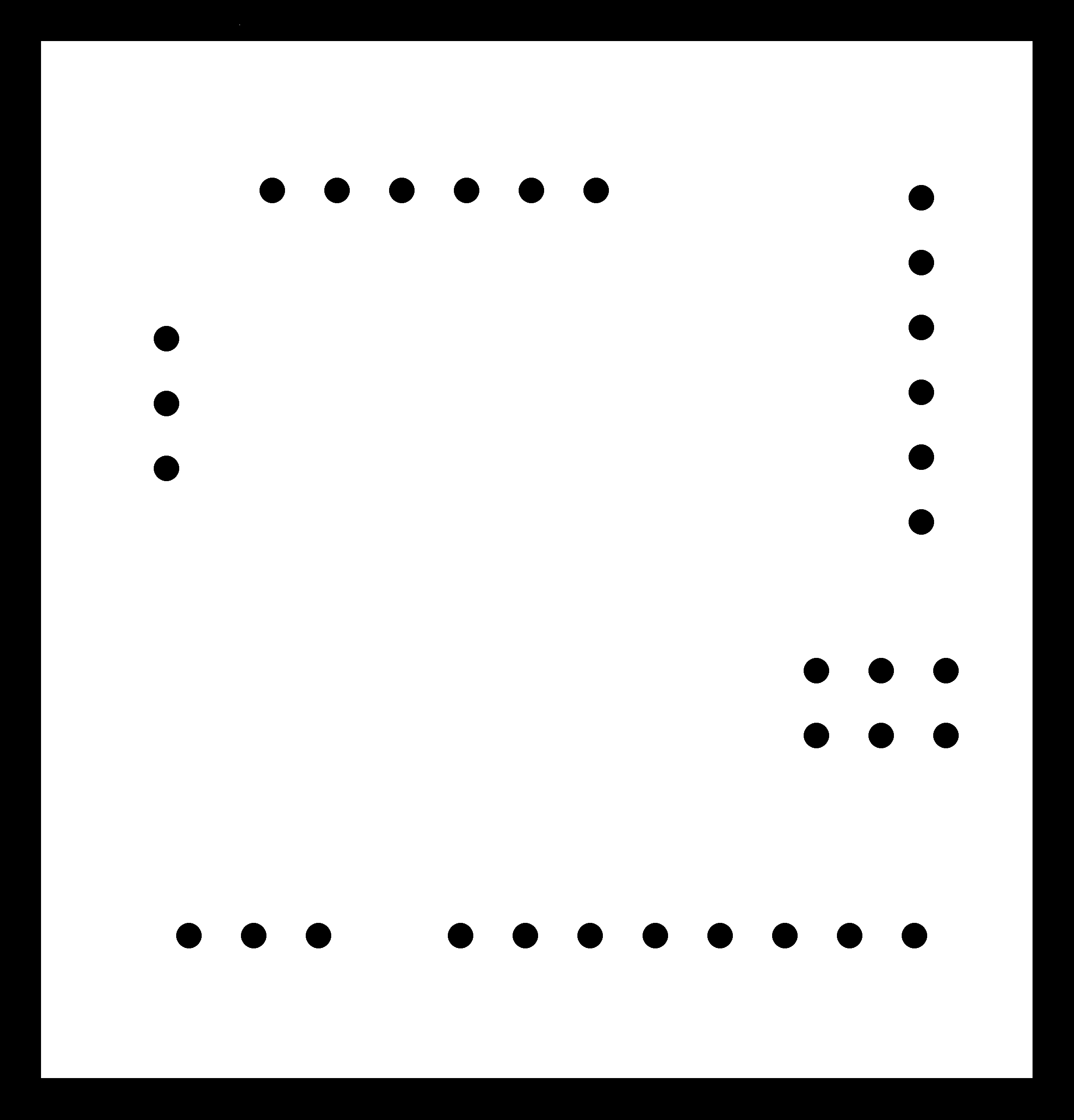
cutout image
Later i used modella and fab modules to mill and cut the board. Then i collected necessary
components for
the board and sticked them side by side to the printout of the
pcb which i designed. This is something i suggest while soldering. Make sure that you have a
printout of
the pcb with components and also have the components sticked corresponding to their name and value.
This
will save a lot of time. Finally i started soldering. Unfortunately in between, the ISP header which
i
soldered
was slanting to a side and to fix that i tried pulling up the the plastic support to remove the
soldering
and brock my pads. The MISO, SCK and RESET pads where broken. The only way to fix the board now was
to use
jumpers, but still i cant use it on a long run as i planned. But i was almost done with the
soldering aand
all.
The
only problem was this. I finally decided to make a new one but before hand i want to test if
everything i
have
designed
is working fine. So i connected some jumpers to the board as you can see below.
fixing, broken pads
I tested the board to be working fine.
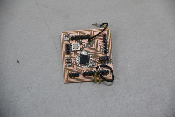
Later i milled the board again and succesfully soldered all the components. This is the
finished board.
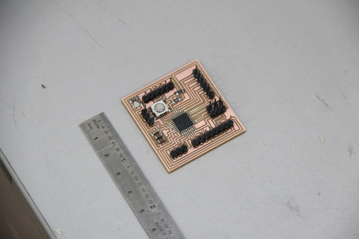
Final Board
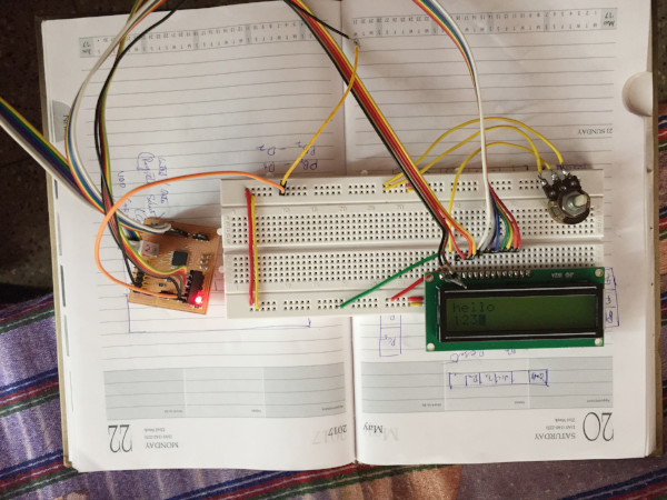
e. Make the connections
Now i have the board and the LCD, its time to make the connections. I connected the PB0-PB7 pins to D0-D7 pins of the LCD respectively. The Gnd and VCC also were connected, put a 10k potentiometer in the VE pin and connected RS, RW, Enable pins to PB5-7. You can see this in the photo below
f. Time to Code
Now i have everything setup. Its time to write the program which can display something on the LCD.There are basically three files namely a header source pair for the LCD related functionalities (called library) and a main file. The library has all the functions and helpers to easily use LCD with a few lines of code.
LCD_lib.c
- #include "LCD_lib.h"
- #include <util/delay.h>
- #include <stdlib.h>
- void InitializeLCD(void){
- //read mode initialization
- LCD_CONTROL_DDR |= 1<<ENABLE | 1<<READ_WRITE | 1<<REGISTER_SELECT | 1<<BACKLIGHT;
- _delay_ms(15);
- //Clear Screen 0x01 = 00000001
- SendCommand(0x01);
- _delay_ms(2);
- //setting to 8 bit mode
- SendCommand(0x38);
- _delay_us(50);
- //4th pos:
- //3rd: display on or off
- //2nd: curson will be on or off
- //1st: cursor blinking or not
- SendCommand(0b00001101);
- _delay_us(50);
- }
- void CheckBusy()
- {
- //turning to input mode
- LCD_DDR = 0;
- //read mode
- LCD_CONTROL_PORT |= 1<<READ_WRITE;
- //command mode
- LCD_CONTROL_PORT &= ~1<<REGISTER_SELECT;
- //run untill the LCD in busy
- while (LCD_PORT >= 0x80)
- {
- ToggleEnable();
- }
- //turning back to output mode
- LCD_DDR = 0xFF; //0xFF means 0b11111111
- }
- // turn enable on and then off
- void ToggleEnable()
- {
- LCD_CONTROL_PORT |= 1<<ENABLE;
- //wait a little bit as the LDC is slow
- asm volatile ("nop");
- asm volatile ("nop");
- LCD_CONTROL_PORT &= ~(1<<ENABLE);
- }
- void SendCommand(unsigned char command)
- {
- CheckBusy();
- LCD_PORT = command;
- LCD_CONTROL_PORT &= ~ ((1<<READ_WRITE)|(1<<REGISTER_SELECT));
- ToggleEnable();
- LCD_PORT = 0;
- }
- void SendCharacter(unsigned char character)
- {
- CheckBusy();
- LCD_PORT = character;
- LCD_CONTROL_PORT &= ~ (1<<READ_WRITE);
- LCD_CONTROL_PORT |= 1<<REGISTER_SELECT;
- ToggleEnable();
- LCD_PORT = 0;
- }
- void SendString(char* string){
- while(*string > 0){
- SendCharacter(*string++);
- }
- }
- void PutStringAtLocation(uint8_t x, uint8_t y, char *string){
- GotoLocation(x, y);
- SendString(string);
- }
- void PutIntegerAtLocation(uint8_t x, uint8_t y, int integer, char numberOfDigits){
- char stringToDisplay[numberOfDigits];
- itoa(integer, stringToDisplay, 10);
- int i;
- for(i=0; i<numberOfDigits; i++) SendString(" ");
- PutStringAtLocation(x, y, stringToDisplay);
- }
- char firstColumnPositionsForLCD[2] = {0, 64};
- void GotoLocation(uint8_t x, uint8_t y)
- {
- SendCommand(0x80 + firstColumnPositionsForLCD[y-1] + (x-1));
- }
lcd.c
- #include "LCD_lib.h"
- int main(void)
- {
- InitializeLCD();
- PutStringAtLocation(1,1, "SHAPEY");
- PutStringAtLocation(1,2, "Ultimate CNC");
- //PutIntegerAtLocation(1,2, 123, 3);
- LCD_CONTROL_PORT |= 1<<BACKLIGHT;
- while(1)
- {
- }
- }
Code review
Here you can see that simply by including the library in our main file we can use lcd display in our projects.
Its all about just initializing the library and calling the PutStringAtLocation() function with the string we want to display. The internals
of the LCD are abstracted in the library.
Source code
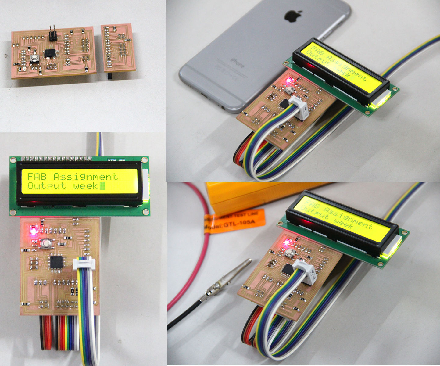
g. Final Result
Now i have programed the LCD to show whatever want. The following is the result. I also made a
library for
controlling LCD display which can used easily used in other projects.
Wired up board
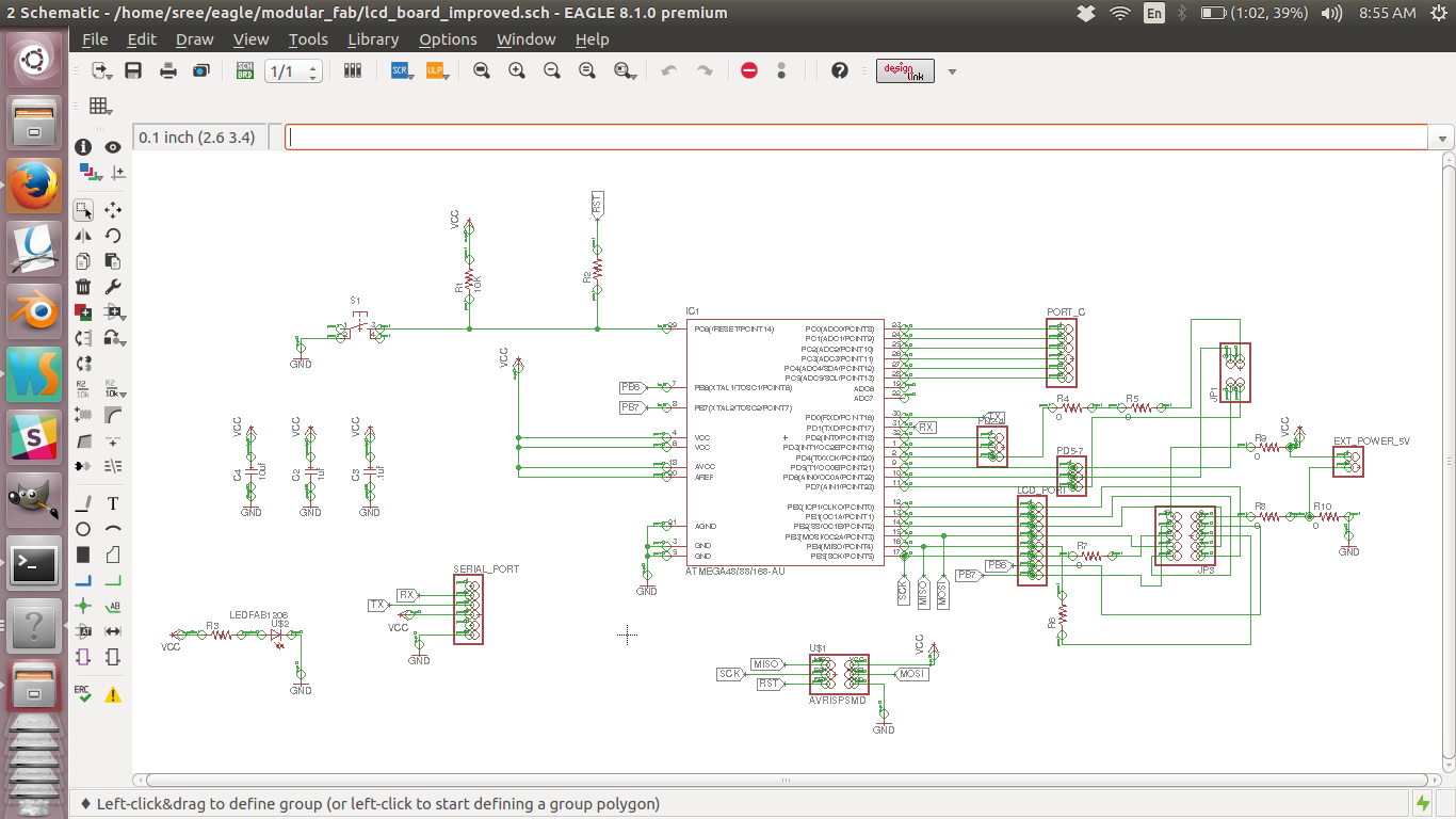
h. Making A Board with connectors
Now i want to make a board, on which i can easily fix and remove the LCD and also which can be
easily
collected to the MC board with connectors. This is made with the intention of final project in mind.
This is expected to give a clean look to my boards and will be easy to assemble.
The following are the trace and cut files.
schematic diagram
board
Trace file of the MC board
Cut file of the MC board
Schematic design
file
Board design file
Trace file of LCD holder board
Cut file of LCD holder board
Schematic design file
Board design file
i. Results
With the new boards i can neatly make connections between the LCD and the MC board.
Final result
j. Problems and solutions
- First time i connected the LCD and programmed, nothing happend. I found that it was getting heated up. On closer inspection i could find that i wrongly connected the VCC and GND. You can see that in the pin diagram it is written VSS and VDD which is quite confusing so make sure you do those connections properly.
- After fixing the VCC and GND issue, i got black rectangles on the display.
This was because i wrongly connected the control pins(RS, RW and enable). Make sure that you have them properly connected. - Initially you might not see anything, dont get frustrated. It might be because of the potentiometer. Try turning it and see if the display comes up.
- I tried to run the same code with the cpu speed pushed upto 16 mhz. This didnt work properly. I just got some random charectors on the display. I am yes to fix that, but i could conclude that if the clock has some problem you will see either black rectangles of some character's of the text you are trying to show.
l. Summary
- Learned to use LCD with atmega328pu microcontroller.
- Created an LCD library which can be used with any project

This work is licensed under a Creative Commons Attribution-NonCommercial-ShareAlike 4.0 International License.