Measure something: add a sensor to a microcontroller board that you have designed and read it.
Learning outcomes:
*Demonstrate workflows used in circuit board design and fabrication.
*Implement and interpret programming protocols.
Have you:
*Described your design and fabrication process using words/images/screenshots.
*Explained the programming process/es you used and how the microcontroller datasheet helped you.
*Explained problems and how you fixed them.
*Included original design files and code.
First step
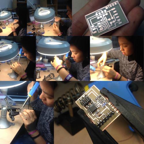
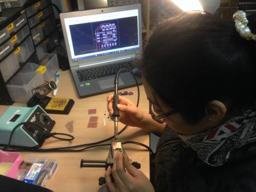
For this assignment I decided to test alternatives that can be useful for my final project so I chose to work with the temperature sensor. Then I started designing with the "Eagle" software, then I performed all the procedure for its construction, first milling the board using the Roland Modela 20X machine and then soldering the components that are needed.
Second step
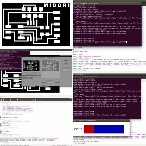
To program the board, I downloaded from the Fab Academy classes, "hello.temp.45.py".
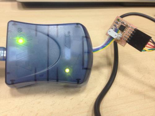
Using Ubuntu, I proceeded to program the microcontroller with the previously downloaded files. First I had to install python and then run it.
The programming was successful, there are the commands: - python hello.temp.45.py /dev/ttyUSB0
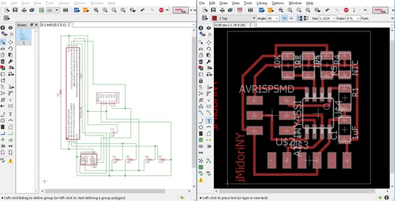
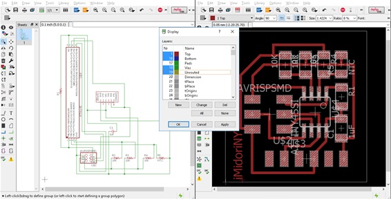
I opened Eagle software and after selected all the components that I needed from the fab library :
Here you have the list:
4 R 10k ohm
1 NTC sensor
1 cap 1 uF
1 Jumper *6
1 Attiny45
1 pin ISP *6
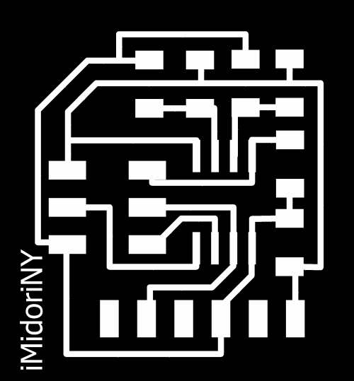
I ordered them and made a board file.
Then exported in .png format
And start milling:
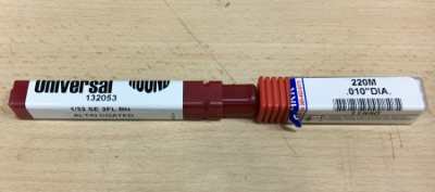
I used 0.010" milling tool to mill and 1/32" milling tool to cut,
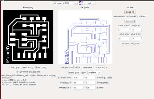
First using the 0.010" milling tool, I change it on the top. Load .png,
Parameters:
diameter (mm): 0.254
overlap: 0.5
offsets (-1 to fill): -1
error: 0.1 pixels
intensity: 0.5
z: -0.1 mm
And make .path
Set xero, moving "x", "y" and "z", click on make .rml and Send it !
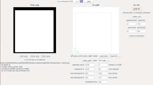
Then, change the 0.010" milling tool for 1/32" milling tool to cut,
Additionally you create a silhouette of the board, you can do it with the same Eagle or with paint, I did it with paint and loaded the image with the same dimensions and set it at the same point of origin.
This is the first time that I did it!, I learned that it is an easier way to get the boards, more accurately, but in Fab Lab Tecsup anyway, they told me to do not do it, because it will damage the base of work.
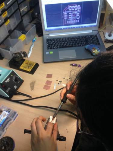
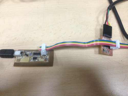
Soldering:
Then I selected the electronic components and started soldering:
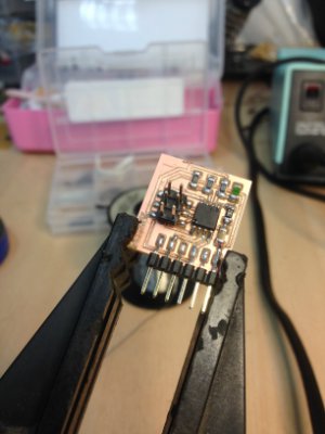
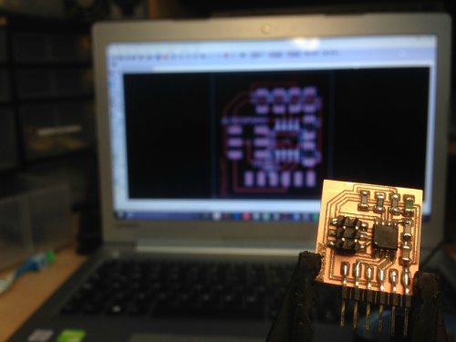
Using this I made the connections correctly in the eagle software.
In case of some correction needed, using datasheet you are able to verify.
In order to program this board is vitally important to use the datasheet that gives you the exact location and name of each pin in a ATtiny 45 microcontroller. Then you are able to make the connections to the input device. In this case a NTC sensor.
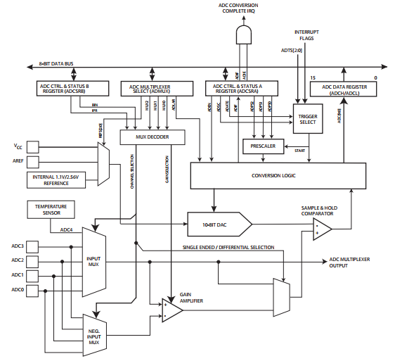
What about ADC?
It convert an analog signal into a digital one. In this case, the analog input gets a sign from 0 to 5 volts and transform it into a digital sign of 8 bits. (From 0 to 255).
The analog-digital converter (ADC) that equips many micro controllers converts an analog external volt in a number, that we can operate with.
Features:
• 10-bit Resolution
• 1 LSB Integral Non-linearity
• ± 2 LSB Absolute Accuracy
• 65 - 260 µs Conversion Time
• Up to 15 kSPS at Maximum Resolution
• Four Multiplexed Single Ended Input Channels
• Two differential input channels with selectable gain
• Temperature sensor input channel
• Optional Left Adjustment for ADC Result Readout
• 0 - VCC ADC Input Voltage Range
• Selectable 1.1V / 2.56V ADC Voltage Reference
• Free Running or Single Conversion Mode
• ADC Start Conversion by Auto Triggering on Interrupt Sources
• Interrupt on ADC Conversion Complete
• Sleep Mode Noise Cancele
• Unipolar / Bibilar Input Mode
• Input Polarity Reversal Mode
The ATtiny25/45/85 features a 10-bit successive approximation Analog to digital Converter (ADC). The ADC is connected to a 4-channel Analog Multiplexer which allows one differential voltage input and four single-ended voltage inputs constructed from the pins of Port B. The differential input (PB3, PB4 or PB2, PB5) is equipped with a programmable gain stage, providing amplification step of 26 dB (20x) on the differential input voltage before the A/D conversion. The single-ended voltage inputs refer to 0V (GND).
The ADC contains a Sample and Hold circuit which ensures that the input voltage to the ADC is held at a constant level during conversion.
Internal reference voltages of nominally 1.1V / 2.56V are provided on-chip. Alternatively, VCC can be used as reference voltage for single ended channels. There is also an option to use an external voltage reference and turn-off the internal voltage reference.
The ADC converts an analog input voltage to a 10-bit digital value through successive approximation. The minimum value represents GND and the maximum value represents the voltage on VCC, the voltage on the AREF pin
or an internal 1.1V / 2.56V voltage reference.
The voltage reference for the ADC may be selected by writing to the REFS[2:0] bits in ADMUX. The VCC supply, the AREF pin or an internal 1.1V / 2.56V voltage reference may be selected as the ADC voltage reference.
Optionallythe internal 2.56V voltage reference may be decoupled by an external capacitor at the AREF pin to improve noise immunity.
The analog input channel and differential gain are selected by writing to the MUX[3:0] bits in ADMUX. Any of the four ADC input pins ADC[3:0] can be selected as single ended inputs to the ADC. ADC2 or ADC0 can be selected
as positive input and ADC0, ADC1, ADC2 or ADC3 can be selected as negative input to the differential gain amplifier.
If differential channels are selected, the differential gain stage amplifies the voltage difference between the selected input pair by the selected gain factor, 1x or 20x, according to the setting of the MUX[3:0] bits in ADMUX.
This amplified value then becomes the analog input to the ADC. If single ended channels are used, the gain amplifier is bypassed altogether.
If ADC0 or ADC2 is selected as both the positive and negative input to the differential gain amplifier (ADC0-ADC0 or ADC2-ADC2), the remaining offset in the gain stage and conversion circuitry can be measured directly as the result of the conversion. This figure can be subtracted from subsequent conversions with the same gain setting to reduce offset error to below 1 LSW.
The on-chip temperature sensor is selected by writing the code “1111” to the MUX[3:0] bits in ADMUX register when the ADC4 channel is used as an ADC input.
The ADC is enabled by setting the ADC Enable bit, ADEN in ADCSRA. Voltage reference and input channel selections will not go into effect until ADEN is set. The ADC does not consume power when ADEN is cleared, so it is recommended to switch off the ADC before entering power saving sleep modes.
The ADC generates a 10-bit result which is presented in the ADC Data Registers, ADCH and ADCL. By default, the result is presented right adjusted, but can optionally be presented left adjusted by setting the ADLAR bit in ADMUX.
If the result is left adjusted and no more than 8-bit precision is required, it is sufficient to read ADCH. Otherwise, ADCL must be read first, then ADCH, to ensure that the content of the data registers belongs to the same conversion.
Once ADCL is read, ADC access to data registers is blocked. This means that if ADCL has been read, and a conversion completes before ADCH is read, neither register is updated and the result from the conversion is lost.
When ADCH is read, ADC access to the ADCH and ADCL Registers is e-enabled.
The ADC has its own interrupt which can be triggered when a conversion completes. When ADC access to the data registers is prohibited between reading of ADCH and ADCL, the interrupt will trigger even if the result is lost.
Starting a Conversion:
A single conversion is started by writing a logical one to the ADC Start Conversion bit, ADSC. This bit stays high as long as the conversion is in progress and will be cleared by hardware when the conversion is completed. If a different data channel is selected while a conversion is in progress, the ADC will finish the current conversion before performing the channel change.
Alternatively, a conversion can be triggered automatically by various sources. Auto Triggering is enabled by setting the ADC Auto Trigger Enable bit, ADATE in ADCSRA. The trigger source is selected by setting the ADC Trigger Select bits, ADTS in ADCSRB (see description of the ADTS bits for a list of the trigger sources). When a positive edge occurs on the selected trigger signal, the ADC prescaler is reset and a conversion is started. This provides a method of starting conversions at fixed intervals. If the trigger signal still is set when the conversion completes, a new conversion will not be started. If another positive edge occurs on the trigger signal during conversion, the edge will be ignored. Note that an Interrupt Flag will be set even if the specific interrupt is disabled or the Global Interrupt
Enable bit in SREG is cleared. A conversion can thus be triggered without causing an interrupt. However, the Interrupt Flag must be cleared in order to trigger a new conversion at the next interrupt event.
Using the ADC Interrupt Flag as a trigger source makes the ADC start a new conversion as soon as the ongoing conversion has finished. The ADC then operates in Free Running mode, constantly sampling and updating the ADC Data Register. The first conversion must be started by writing a logical one to the ADSC bit in ADCSRA. In this mode the ADC will perform successive conversions independently of whether the ADC Interrupt Flag, ADIF is
cleared or not.
By this code I can understand that here is the formula that measures the temperature and how the logic is done to be able to register as increase and reduce. But I have not risked changing anything. In this code .py is the interface that interacts with us to visualize this data, in this part if I made a change, look here and then try it.
.py code:
#
# hello.temp.45.py
#
# receive and display temperature
# hello.temp.45.py serial_port
#
# Neil Gershenfeld
# CBA MIT 3/27/12
#
# (c) Massachusetts Institute of Technology 2012
# Permission granted for experimental and personal use;
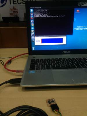
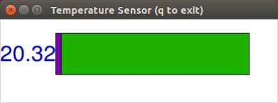
Here is the code that I change, I'm not a specialist of this topic, but I tried my best, this part is about how the interface of temperature sensor looks, I change it with differente name, color and dimension