Exercise 09 - Mechanical Design.
Requirement
- Make a machine, including the end effector, build the passive parts and operate it manually.
- Document the group project and your individual contribution
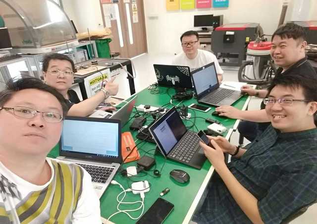
Forming of group
This week assignment is to assemble a configurable modular machine based on the “CardBoard machine” from James Coleman and Nadya Peek. Two weeks later we are to automate it using the Python Programming during Machine Design week.
Group Discussion
After much brain-storming and research through past projects, we decided to build a 3-axis plotter Machine.
Workload Distribution
As this is a group project that spread over 2 weeks (22 Mar 2017 - 5 Apr 2017), we have decided to split up the workload as follows for the mechanical design:
- Study the suitability of using the Cardboard or Plywood for housing - (Ngiap Peng/Jeff/Louis/Hong Guan/Tiang Seih)
- Design and Lasercut the Paper/Cardboard/Plywood housing - (Jeff/Louis)
- Design and Lasercut the module frame body - (Jeff/Hong Guan)
- Make and Mill the Electronic Parts - (Jeff/Tiang Seih)
- Luggage design - (Jeff)
- Explore the Gestalt Framework - (Ngiap Peng/Tiang Seih)
- 3D design & Print the Pen Holder - (Ngiap Peng) Connecting and Testing the Stepper Motor - (Hong Guan/Louis)
- Assemble the housing and test with the Stepper Motor - (Ngiap Peng/Jeff/Louis/Hong Guan/Tiang Seih)
Documentation
- Creating/Updating the Group and Mechanical Design Page - (Tiang Seih)
- Photographer - (Hong Guan)
- Videographer - (Louis)
My contribution for Mechanical Design
- Study the suitability of using the Cardboard or Plywood for housing
- Design and Lasercut the Paper/Cardboard/Plywood housing
- Design and Lasercut the module frame body
- Make and Mill the Electronic Parts
- Luggage design
- Assemble the housing and test with the Stepper Motor
Make and Mill the Electronic Parts (FABNET)
The FabNet is a multi-drop network, meaning that multiple modules (a.k.a. nodes) share a single set of communication wires. Signaling is differential based on the RS-485 specification.
The FABNET is necessary as it will supply voltage to the other boards (Gestalt node), allow communication between the FABNET and the computer. Our first design for FABNET is base on Iian Moyer, which was later inform by our local instructor to use BAS's design instead cos his design provide more direct connection straight through ribbon cable to the Gestalt node. Bas's design can be found here.
To stuff the board we need the following components:
- 1 - 2x5 pin connector
- 1 - 1x4 pin connector
- 2 - 600 Ohm resistors
- 1 - 6 pin connector
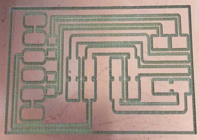
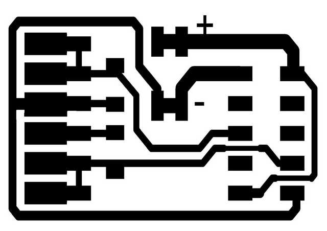
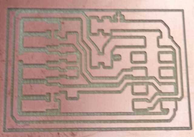
We made some modification to the original image template for Bas's FABNET board by removing the all the unwanted text and reducing some of the track width. Upon milling the board, proceed to stuff the components onto the bridge board.
While soldering the 6 pins connector, realize that the PADS on the board are way too wide apart and the some of the connector pins were causing short-circuit. Have to re-work, re-solder and some minor isolation to the connectors before getting it working.
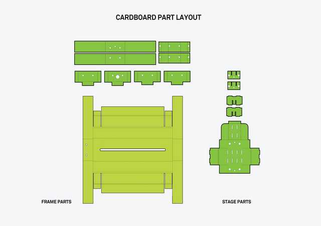
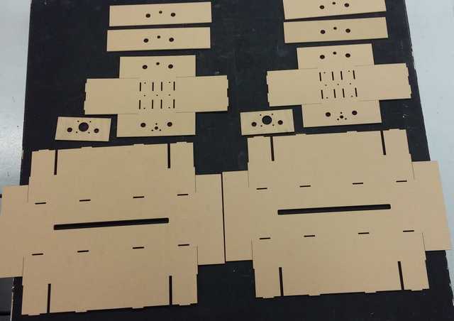
Design and Lasercut the Paper/Cardboard/Plywood housing (MTM Housing Design)
With limited time-frame and knowledge at hand, we browse through other past year project for possible housing design to hold the MTM kit. Using the original design template from Nadya Peek, we decide to modify it suit our project idea.
Cardboard is the first material which come to our mind and we decide to use it for the housing, cos cupboard provide more flexibility and is environmental friendly.
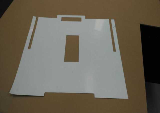
Study the suitability of using the Cardboard or Plywood for housing
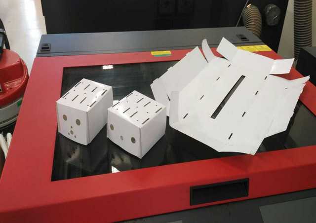
Before we jump directly to use cardboard, we use paper to cut the outline of the frame and stage to see if the design works.
Attempt No 1 : using 2 ply-cardboard
With some ex-stock of 2 ply-cardboard left in our school, we tested the design with it.
As a result, we found that the 2 ply is too thick, and the cupboard tears while bending the joint.
Attempt No 2 : using 1 ply-cardboard
This time round, we got some 1 ply-cardboard. The cardboard used was thinner which give better result while bending. Because of design purpose, there are engraving line for marking but this causes tearing on the cardboard
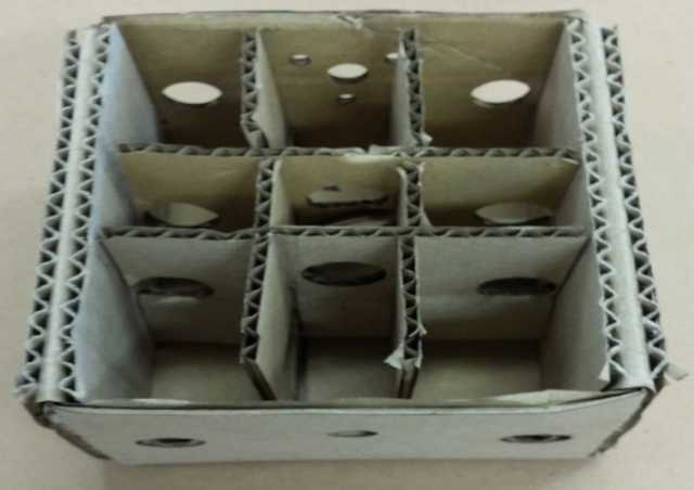
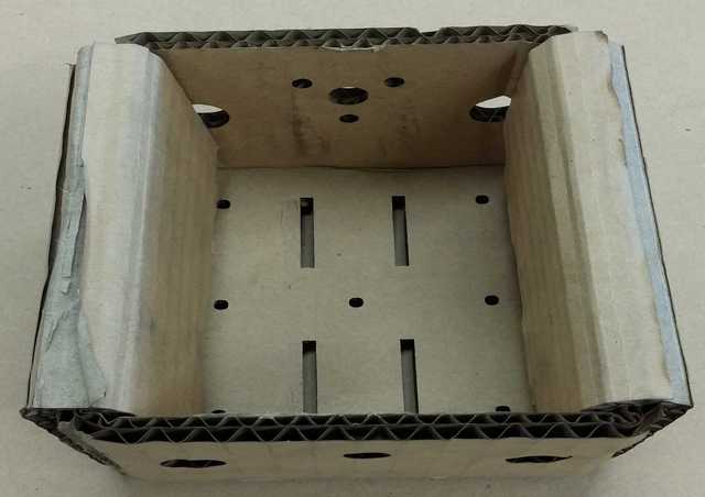
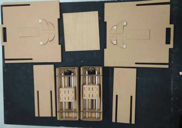
Attempt No 3 : using 1 ply-cardboard without engraving line
With similar design, all engraving lines are remove and make some modification to the size of the stage and frame to suit our design
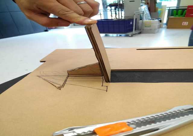
Luggage design - Make it Portable
With all parts of MTM modular and portable, we therefore want to make it mobile. So we decided to incorporate the idea of a suitcase into the machine frame.
Similar to frame and stage, a test cut for the propose suitcase done using paper first before jumping into cardboard.
The design for our MTM is a 3 axis plotter, so basically one of the module will be slotted into the hole in the middle of the luggage, supported by a tongue and a butterfly design wedge to provide additional support to hold the module.
The images below is to show how we prototype the design.
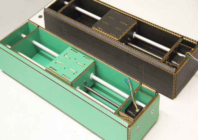
Hero Shot of our suitcase MTM
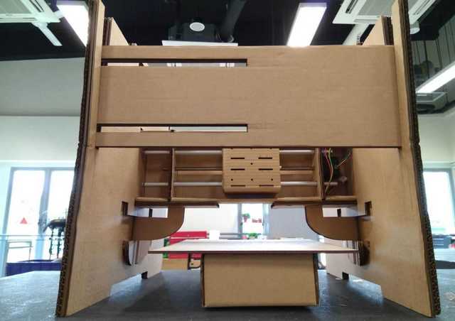
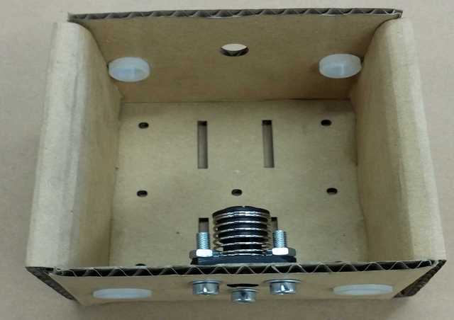
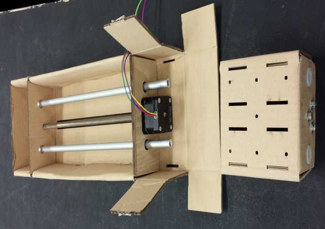
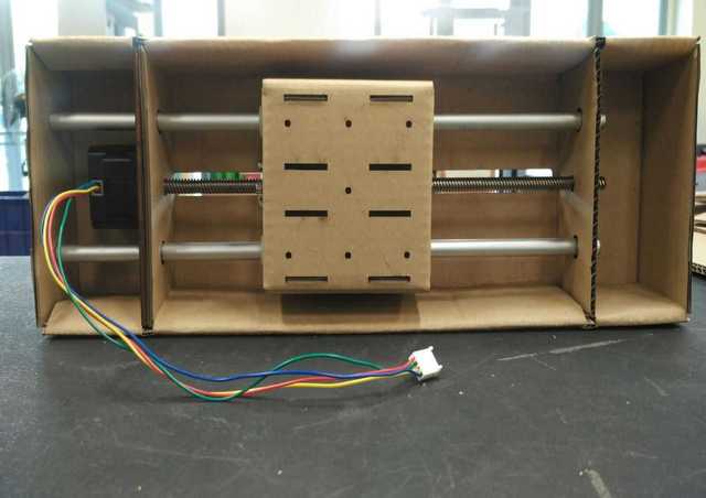
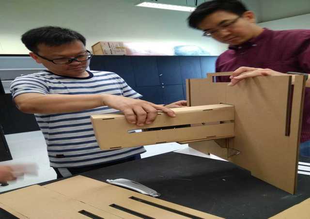
Assemble the Cardboard design housing with the Stepper Motor
After assembly, we need to be able to using our hands to automate the MTM by turn the gear thread rod to see if the stage is moving up and down according. If that works, it shows that our assembly is ok and ready to proceed on to machine design week.
More information can be found on our other group member's site
Downloads
Casing - here
Housing - here
Return to top