Exercise 4 - Electronics Production
Requirement
- Describe the process of milling, stuffing, debugging and programming an in-circuit programmer (FABISP).
This week's project was the most challenging as compared to the past few weeks. We got to explore Surface-mount Technology (SMT) is a method for producing electronic circuits in which the surface-mount components (SMD) are mounted or placed directly onto the surface of printed circuit boards (PCBs), and milling out the PCB board with a CNC machine.
FabISP
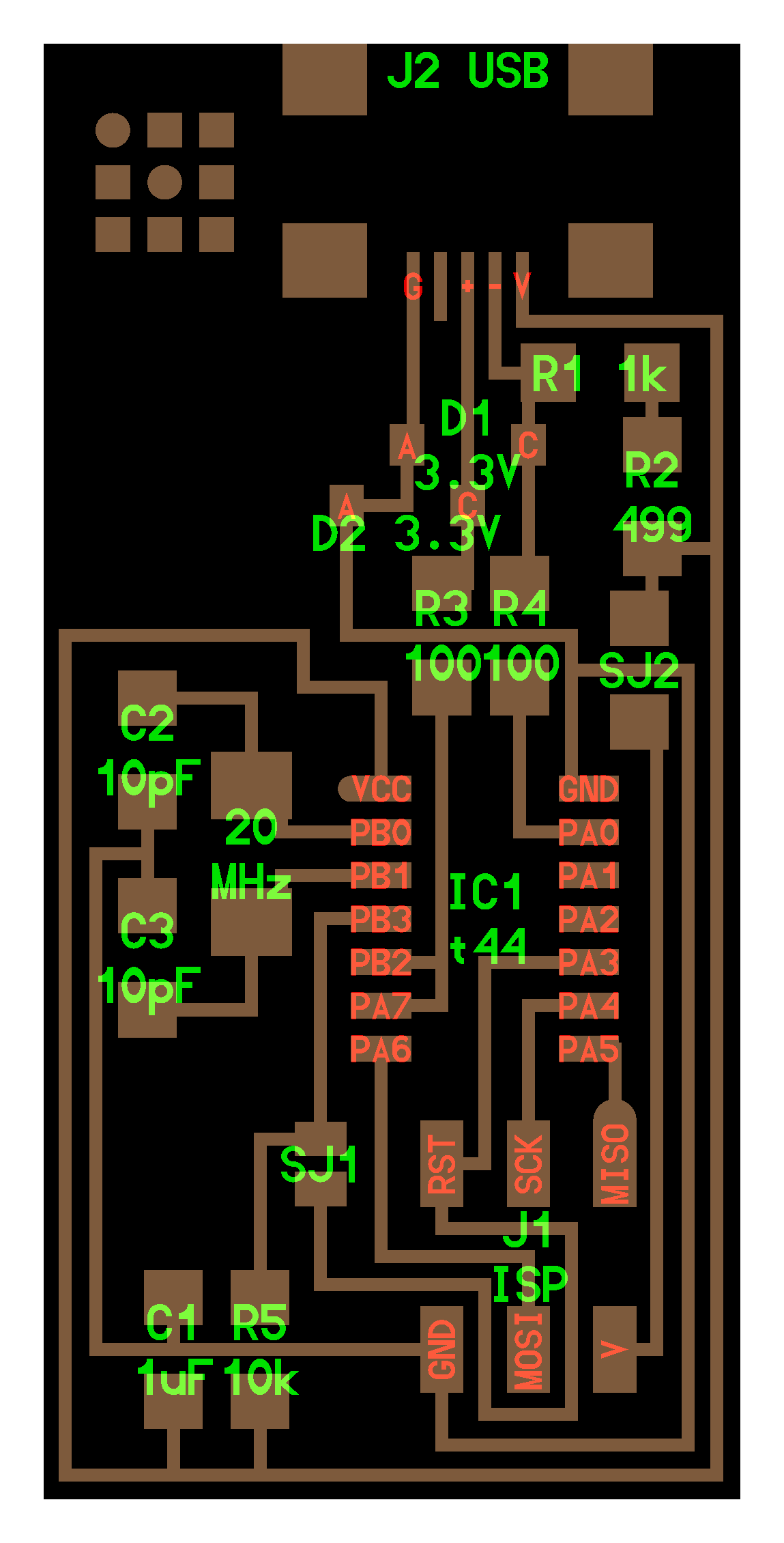
David Mellis designed this simple-to-construct FabISP, a fab-able in-system programmer, designed to be easy to replicate, it uses a one-sided PCB and a single micro-controller.
To get started, download the image for the FabISP, or download a copy of Neil's FabISP here hello.ISP.44 board, traces, and interior circuit board file
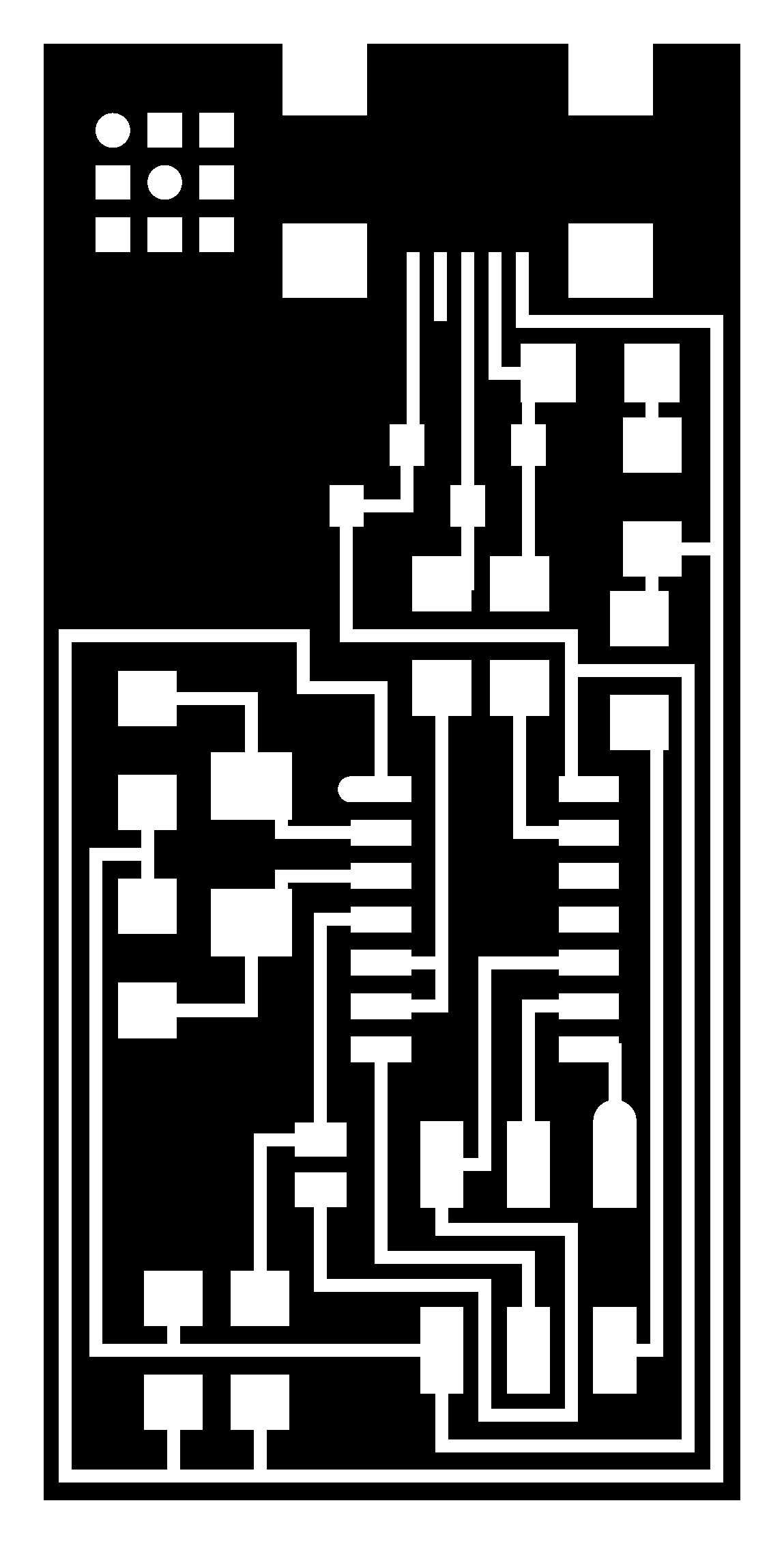

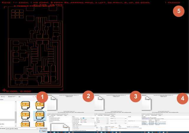
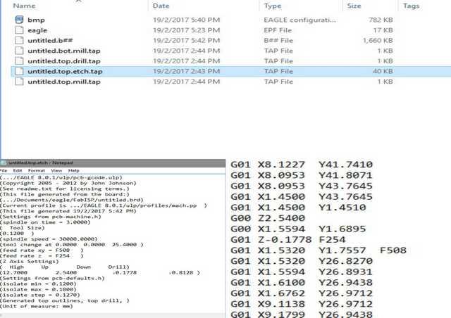
G-code from Autodesk Eagle
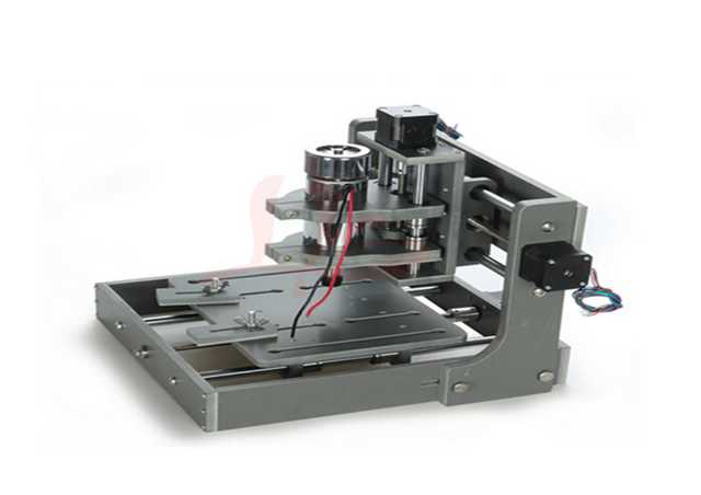
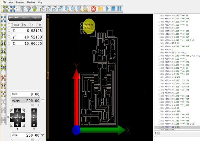
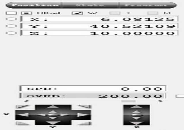
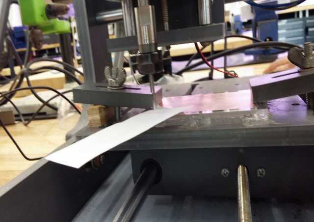
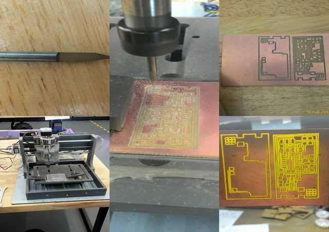
For this assignment, a CNC B2020 Generic which is compatible with Mach 3 software is used to mill the PCB, and this machine operates on G-code. Luckily, our local instructor was prepared and have the CNC ready with some tested preset setting. After his demo, we proceed to fabricate our individual FABISP PCB and we spend a good whole day working on the mini CNC getting ISP board out.
G-code (also RS-274), which has many variants, is the common name for the most widely used numerical control (NC) programming language. It is used mainly in computer-aided manufacturing to control automated machine tools. I will be using Eagle to design the PCB.
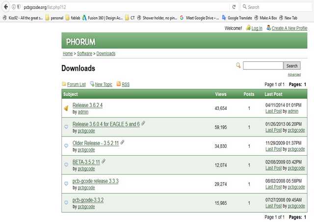
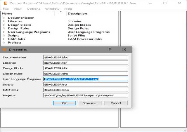
First, download the extension pcbgcode for Eagle, then extract and copy all files into Eagle folder -> ULP folder.
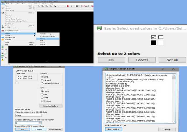
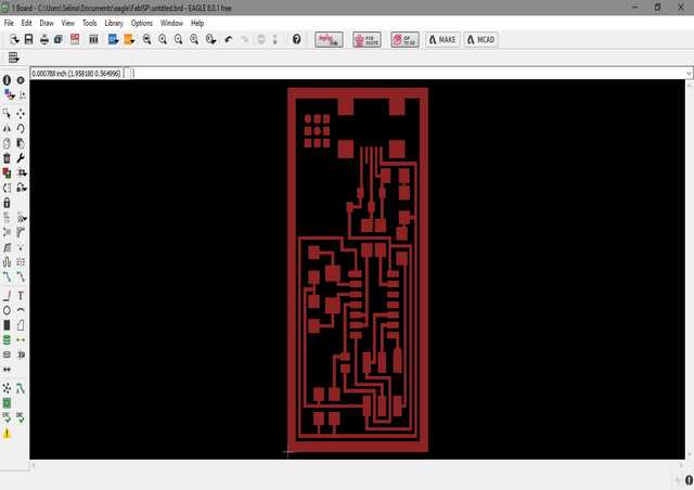
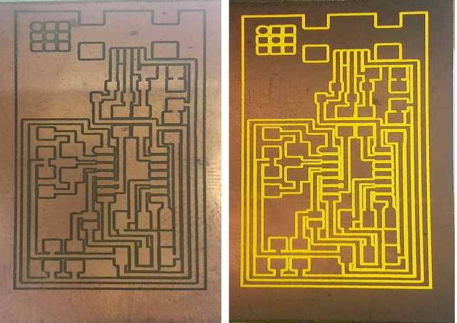
Instead of milling out the traces and pads for the SMD, our approach are to isolate the traces and pads. In order to that, we need to invert the colour for traces. Using PicPick to invert the colour for "hello.ISP.44.traces" and save in BMP format (Eagle can only import BMP).
Stuff the board
Based on the schematic, the components needed are:
- 1x ATtiny44 micro controller
- 1x 1uF capacitor
- 2x 10pF capacitor
- 2x 100 ohm resistor
- 1x 499 ohm resistor
- 1x 1K ohm resistor
- 1x 10K ohm resistor
- 1x 6 pin header
- 1x USB connector
- 2x 0 ohm resistors as jumpers
- 1x 20 mHz Crystal
- 2x 3.3V Zener diode
- 1x usb mini cable
- 1x ribbon cable
- two 6 pin connectors
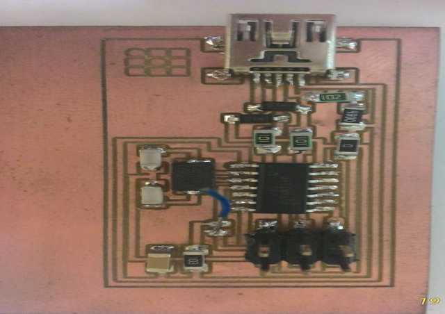
Soldering the Components
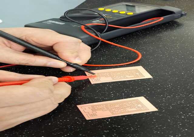
Soldering itself was a big challenge and additional to that the size of SMD makes it even more difficult. Before soldering, we will advice to wash the board to remove any residue left over by the mill. Then a test of connectivity of the board to ensure that there is no short or open circuit.
Most of us were lucky enough to collect our SMD components the day after, and get started working on it. But due to work commitment, I can stuff the board during weekends. And thanks to our colleague from the library Maker's Space, for loaning out a set of SMD rework station.
Soldering was something new and furthermore, SMD components. I felt that the most difficult components to were the USB connector and the 6 pin header, cos they are either too fine too solder or it come off easily after solder.
Before soldering on the actual ISP board, I did some trial practices on some left over copper board to get the feel of soldering. With some confident, I started working on the FABISP. After 3 solid hours, I am finally done with FABISP.
|
|
Things to look out for while soldering:
- Advisable to use a temperature controlled soldering iron with fine tip
- Temperature must be hot enough so that solder lead melt when come in contact with the hot iron.
- Soldering wick is very useful to soak up excess, unwanted solder from the board.
- Be careful not to create unintentional solder short circuits with adjacent joints and not too little solder that components did not form proper connection with the copper pads (which was the main problem for most of us).
Testing the Stuff PCB board
Do the "Smoke Test". Plug the FabISP into your computer via the mini USB cable. If you get an error message from your computer that the board is drawing too much power and that the computer is shutting down the USB port, you have a short somewhere on your board. Else the computer should detect a unknown or malfunction device. Proceed to "Install the necessary software for micro-controllers programming."
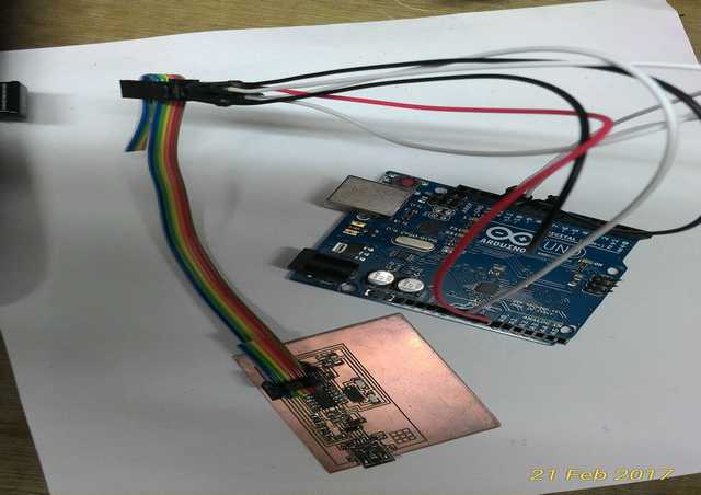
Using an ISP to program the FABISP
We cannot program an ISP without a working ISP. Arduino can be reprogram as an ISP but I encounter some errors while using ArduinoISP (may be the problem is due to my poor soldering and not the Arduino), so instead I am able to get an working FABISP from last year student.
For reference only * Connect the Arduino Uno to computer. Under File -> Examples -> ArduinoISP, upload the program to the Uno board. *
Take note of the following connections while using Arduino as ISP.
| Uno | FABISP |
|---|---|
| 10 | Reset |
| 11 | MOSI |
| 12 | MISO |
| 13 | SCK |
| 5V | VCC |
| GND | GND |
Programming the FABISP using WinAVR
Read through this useful documentation. before jumping in to program the ISP. I am a windows user, so will be using the WinAVR instead of Mac OS or Ubuntu.
There are 2 parts to get the FABISP board to work as an ISP.
- Install the software needed to program ISP, in this case: WinAVR.
- Downloading the require firmware. for the ISP
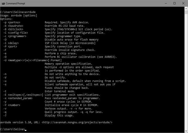
WinAVR (pronounced "whenever") is a suite of executable, open source software development tools for the Atmel AVR series of RISC microprocessors hosted on the Windows platform. After installation, we are able to "avrdude" command in Windows Command Prompt to load the firmware to make our FABSIP. I found this site informative and helpful in understanding the use of avrdude.
The firmware.zip contain the hex file needed for the FABISP. On Windows Command Prompt, type: avrdude (usage of avrdude).
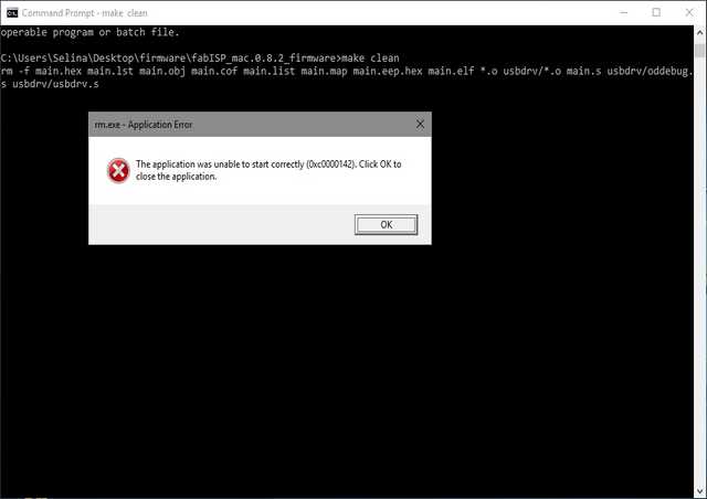
From the firmware on Windows Command Prompt, there are a few "make" command where can use to program the ISP (looking at make command, it is actually a compile of avrdude command make easy). Execute the following in order.
- make clean : delete some predefine files
- make hex: create the hex file needed for ISP
- make fuse: to program the fuse of target ISP
- make program: to load in the hex file to target ISP
While using the make clean, I encounter error where I can't solve and in the end I use the avrdude command instead.
Looking through avrdude, the command for programming for my FabISP is via the following:
avrdude -c usbtiny -p t44 -U lfuse:w:0xff:m -U hfuse:w:0xdf:m -U flash:w:main.hex
- avrdude: command line
- -c -> specify the programmer use (to find out the list of programmer use: avrdude -c ?), in this case is "usbtiny"
- -p -> specify the target board type (to find out the list of board use: avrdude -p ?), this is case is "t44" (ATtiny44)
- -U -> does the programming.
- lfuse:w:0xff:m -> Burning low fuse memory:FUSE_L:write:0xFF
- hfuse:w:0xdf:m -> Burning high fuse memory:FUSE_H:write:0xDF
- -U flash:w:main.hex -> program, flashing by writing the main.hex to target
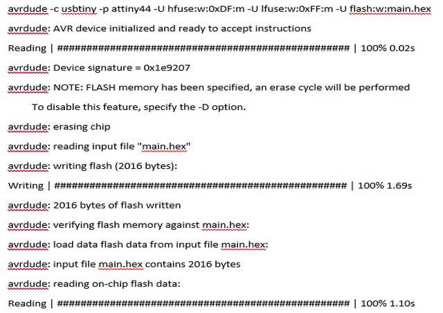
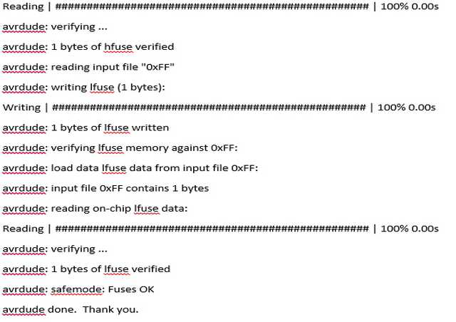
If everything is smooth sailing, you should get the following:
|
|
Testing the FabISP
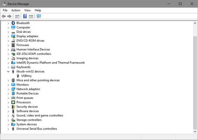
- Make sure that FabISP is detected when you plug into the computer. Else try installing the driver for USBtiny here
- USBtiny can be found inside Device Manager
- Connect another target to FABISP via the 6Pins connector
- Program the new FABISP. using: avrdude -c usbtiny -p attiny44 -U lfuse:w:0xff:m -U hfuse:w:0xdf:m -U flash:w:main.hex
After successful programing, you can either left it or remove the solder bridge to prevent any further programming or accidentally reprogramming the ISP micro-controller.
During the course of programming the FABISP, I have encounter some error while flashing the main.hex file to the target T44. Those error can be either due to cold/ loose connection of components or programmer can't communication with target board
|
|
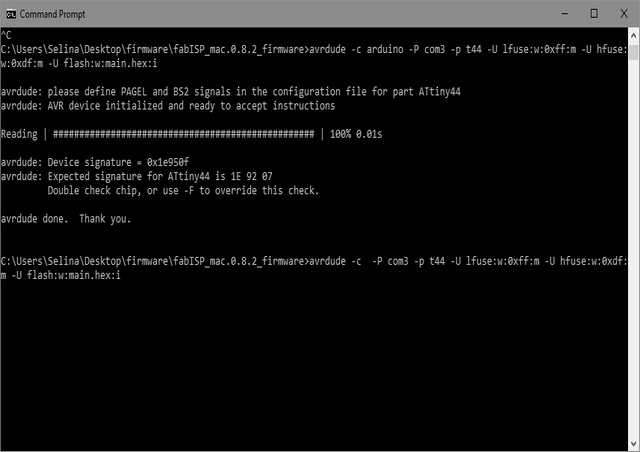
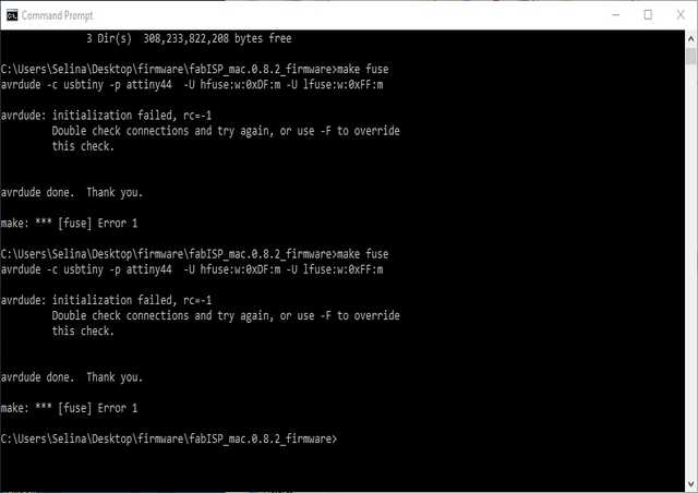
Troubleshooting of FABISP
- Check for visually for possible cold solder (not shiny and smooth), and short or open circuit with a multi-meter
- Search the web for possible solution for the errors
- Vcc and Grd are not shorted, else it draw too much power and will shut down the computer USB which require restarting
- After successfully programming, sometime the computer is unable to detect the USBtiny, try step 1 again.
My thoughts
Stress, stress. stress. This week experience was really an unforgettable, cos we spent almost 6 whole days from starting from Eagle to milling to stuffing the PCB to programming and last but not least testing and troubleshooting, just to finish and get 1 board to work. And such board (ISP) is commercially available at very low cost, I did learnt a lot from this but is the effort worth? hmmm, will I still remember few weeks down the road? I wonder???
Lastly, thanks to the support given by our fellow colleague and past year FabAcademy students. My FABISP is done.
Return to top