Exercise 09 - Mechanical Design.
Requirement
- Make a machine, including the end effector, build the passive parts and operate it manually.
Planning
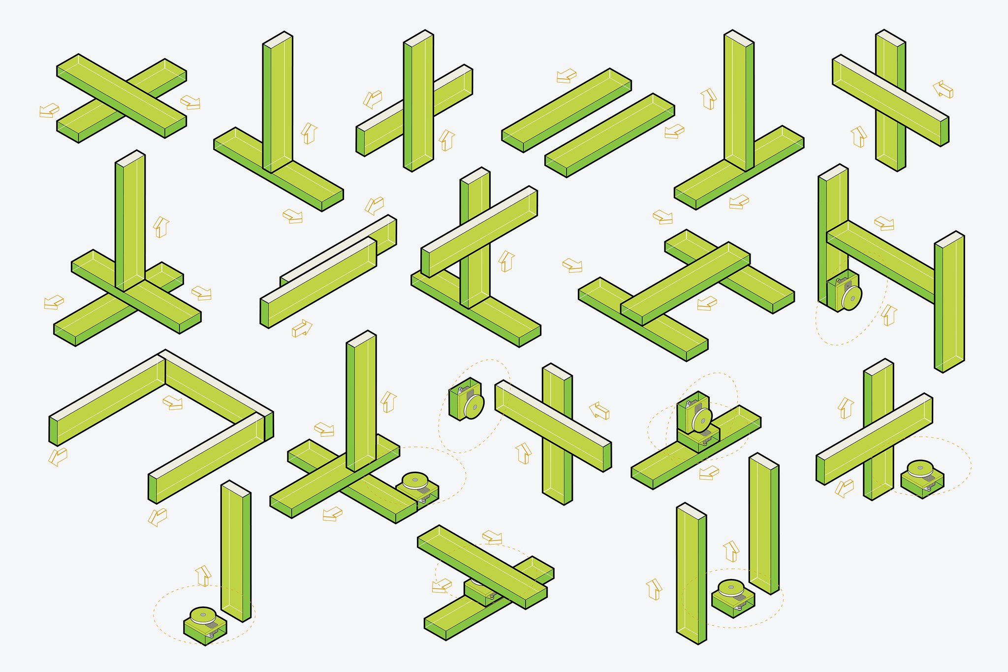
This week assignment is to assemble a configurable modular machine based on the "CardBoard machine" from James Coleman and Nadya Peek. Two weeks later we are to automate it using the Python Programming.
This is a group project but given the fact that none of us has mechanical or programming background let alone being a builders or thinkers. Therefore we have decided that whatever decisions made it has to be group decision and each one of us will still contribute, participate and collaborate as an individual.
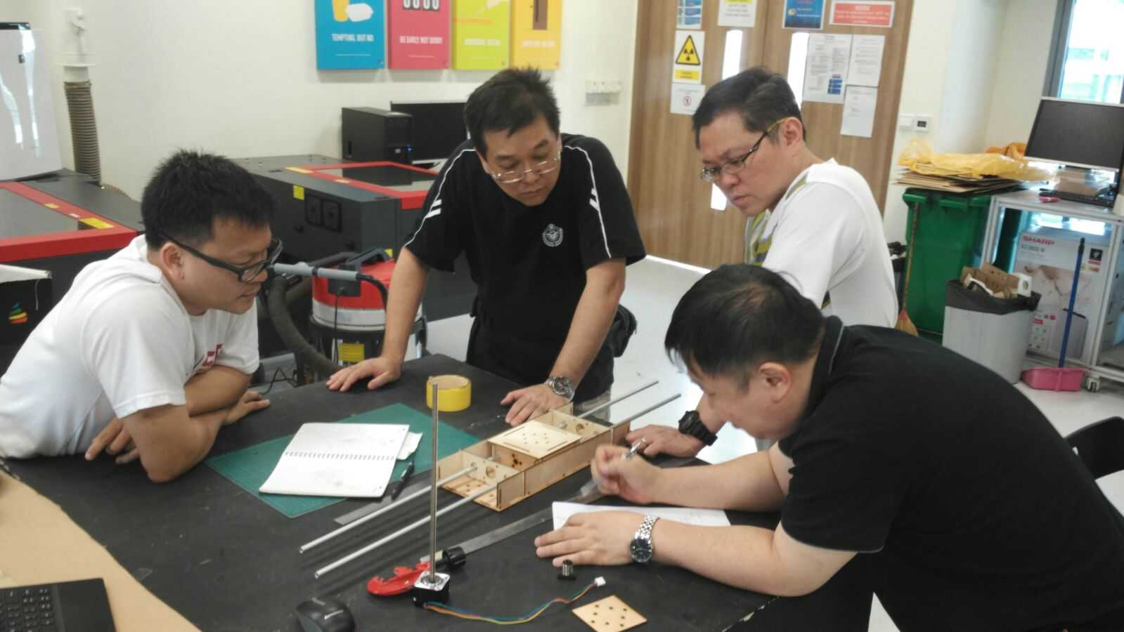
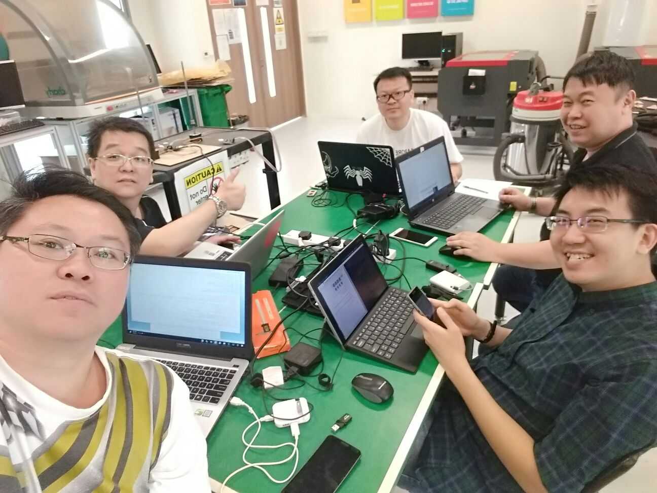
Upon receiving the MTM Kit, we met and look through past year projects, discuss the possible project we intend to do or built.
|
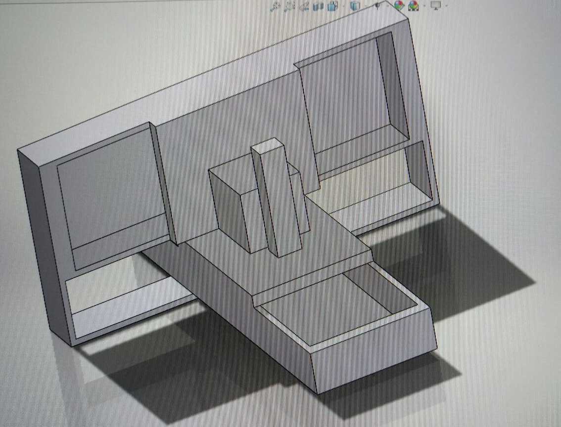
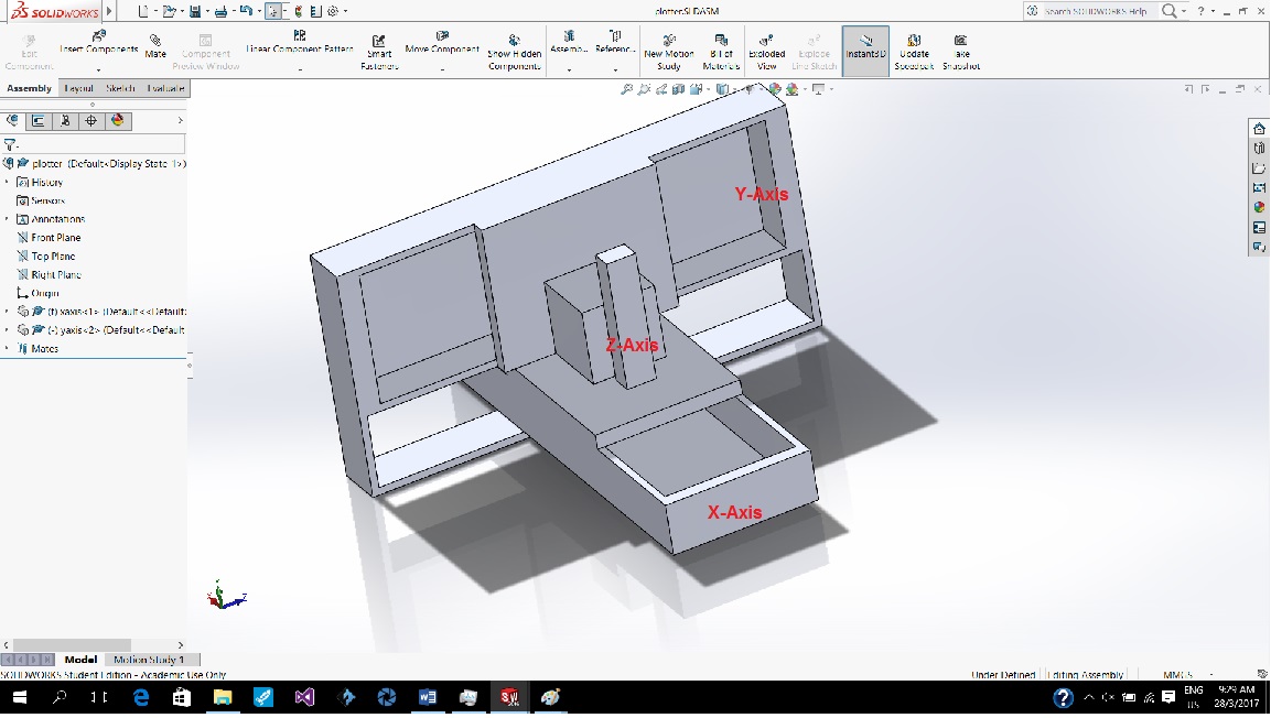
After much discussion, we decided to build a 3-axis plotter Machine.
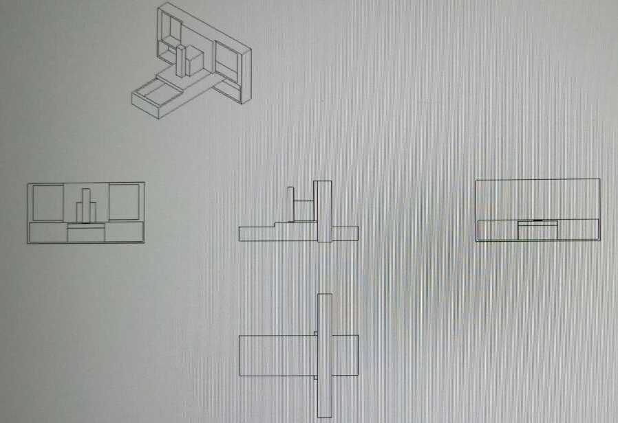
We do a quick search for some similar past year projects to have a rough idea on the structure require and materials for the housing. A conceptual design for our plotter Machine has been drafted by Ngiap Peng.
Workload Distribution
As this is a group project that spread over 2 weeks (22 Mar 2017 - 5 Apr 2017), we have decided to split up the workload as follows for the mechanical design:
- Study the suitability of using the Cardboard or Plywood for housing - (Ngiap Peng/Jeff/Louis/Hong Guan/Tiang Seih)
- Design and Lasercut the Paper/Cardboard/Plywood housing - (Jeff/Louis)
- Design and Lasercut the module frame body - (Jeff/Hong Guan)
- Make and Mill the Electronic Parts - (Jeff/Tiang Seih)
- Luggage design - (Jeff)
- Explore the Gestalt Framework - (Ngiap Peng/Tiang Seih)
- 3D design & Print the Pen Holder - (Ngiap Peng)
- Connecting and Testing the Stepper Motor - (Hong Guan/Louis)
- Assemble the housing and test with the Stepper Motor - (Ngiap Peng/Jeff/Louis/Hong Guan/Tiang Seih)
- Documentation
- Creating/Updating the Group and Mechanical Design Page - (Tiang Seih)
- Photographer - (Hong Guan)
- Videographer - (Louis)
Housing Design for the Project
With the limited timeframe, we browse the website for possible housing to hold our stepper motor and rod as we intend to shorten the frame from the original design from Nadya Peek. As Nadya parametric settings was based on Rhino but none of us knew how to use Rhino software. Later we find out that Grasshopper the plug-in for Rhino is the one that does the trick.
Meaning we got to familiaise ourselves with 2 software in such a short time frame is not ideal so we quickly search for possible housing and derive at the possibility of using past year archive project from the MTM Group 1 and Group 2. We have chosen to use the housing for MTM Group 2 as its housing is more of a modular based and is more suitable for our proposed project.
The materials used for the housing becomes a debate as we are tossed between cardboard and plywood. For firm control, we decided to go for plywood using the housing by the past year project from MTM Group 2.
Lasercut the Cardboard Design Housing
Lasercut is done for the housing using plywood. We realise the fitting of the housing is a bit loose despite considering the kerf. So back to the drawing board and switch back to use Nadya's housing. Managed to find the Nadya's housing in dxf format. Scale up the design in AI and made some modification to the frame and stage to suit our design.
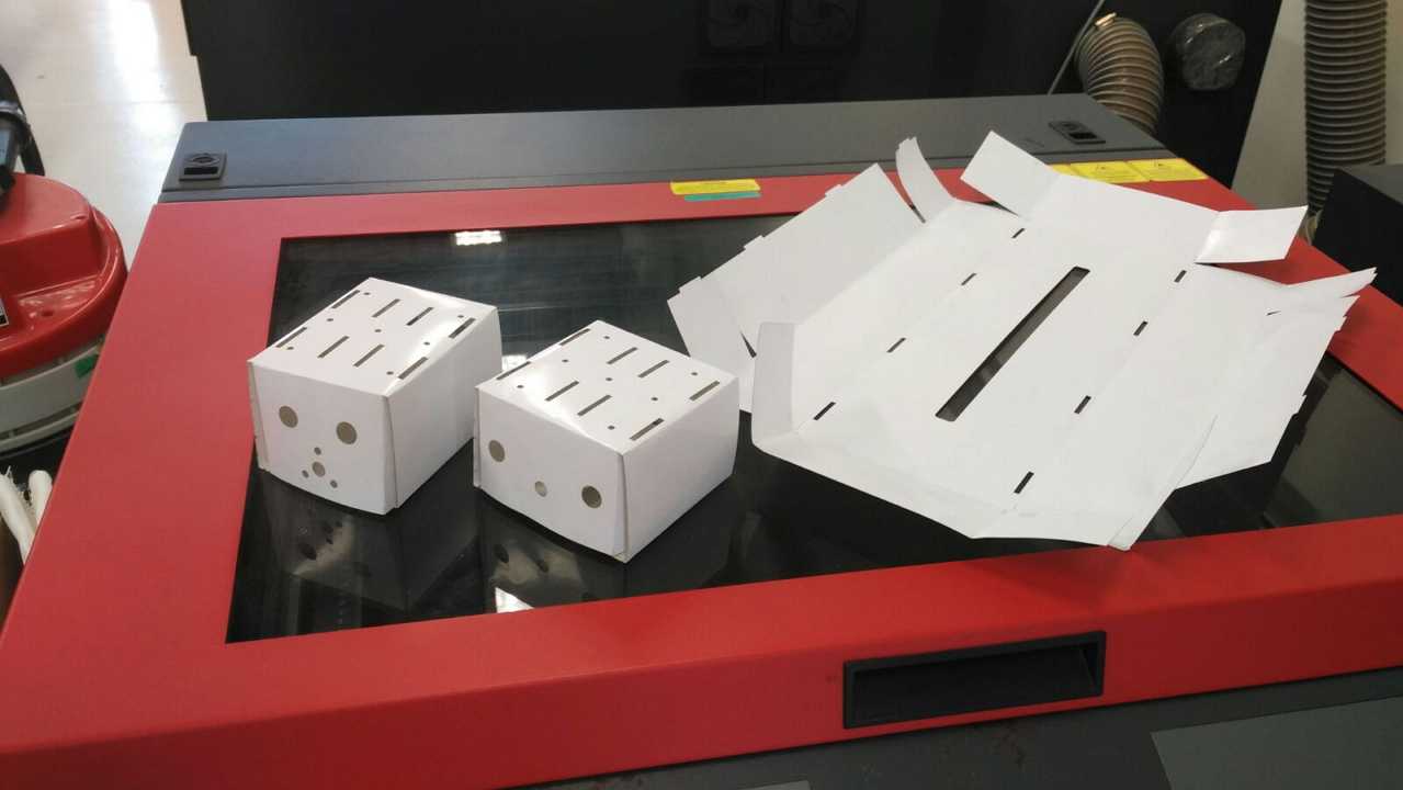
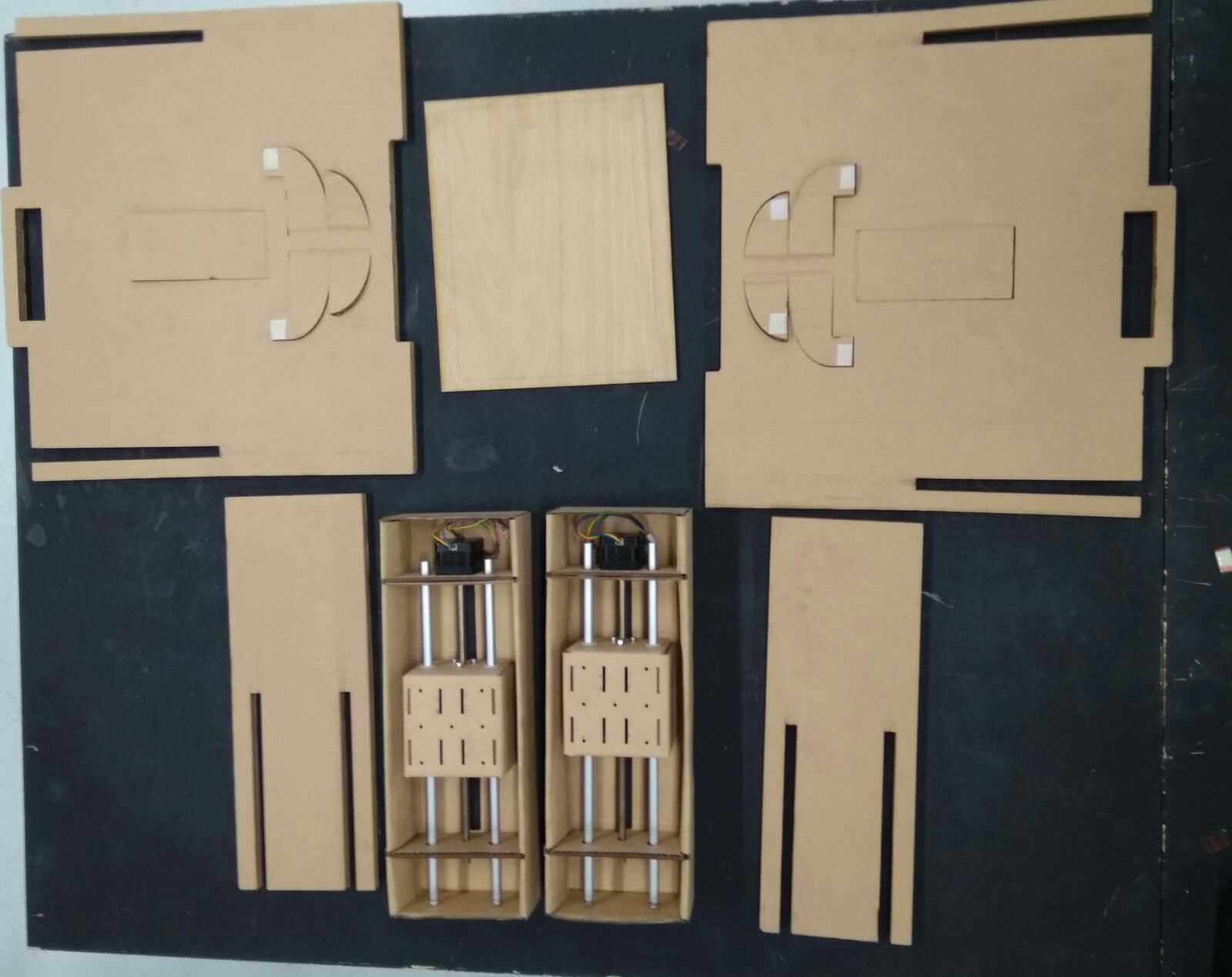
Papercut design
Before we cut the cardboard, we use paper to cut the outline of the frame and stage to see if everything works.
Attempt No 1 using cardboard
The cardboard used was too thick
Attempt No 2 using cardboard
The cardboard used was thinner but the engraving cause tearing on the cardboard
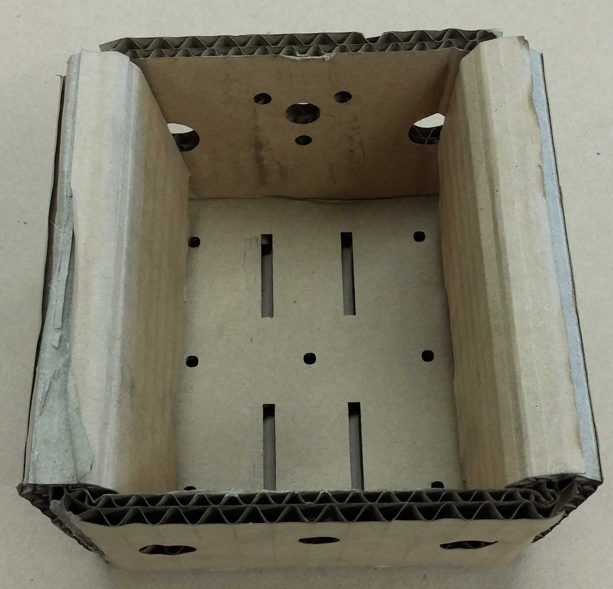
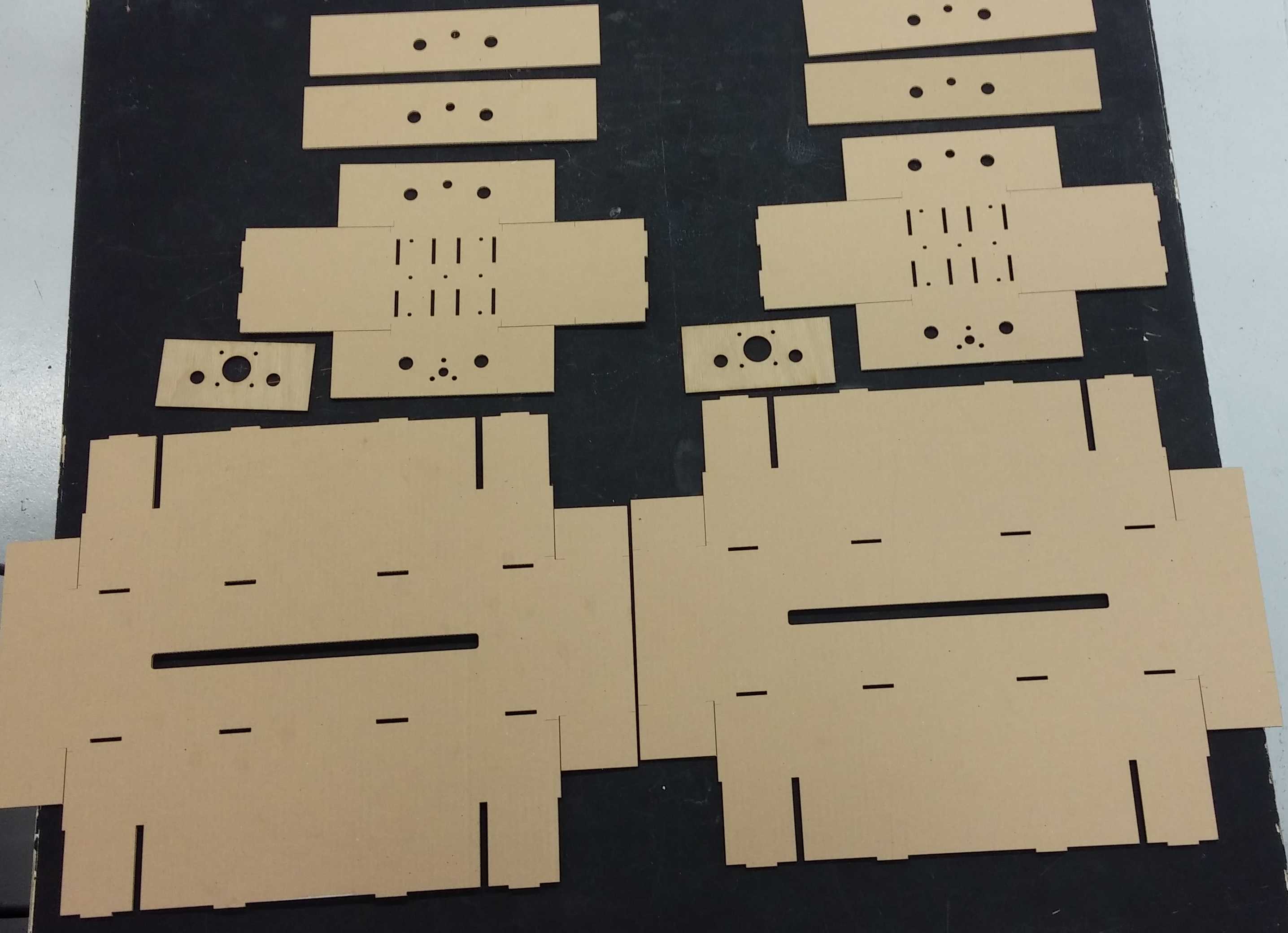
Attempt No 3 using cardboard
Made some modification to the size of the stage/frame to suit our design and also removing the engraving. The result as shown
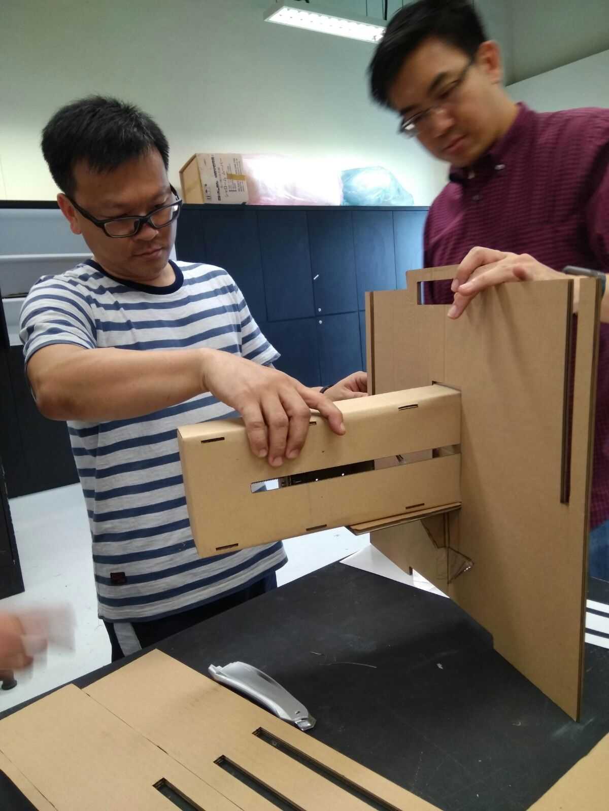
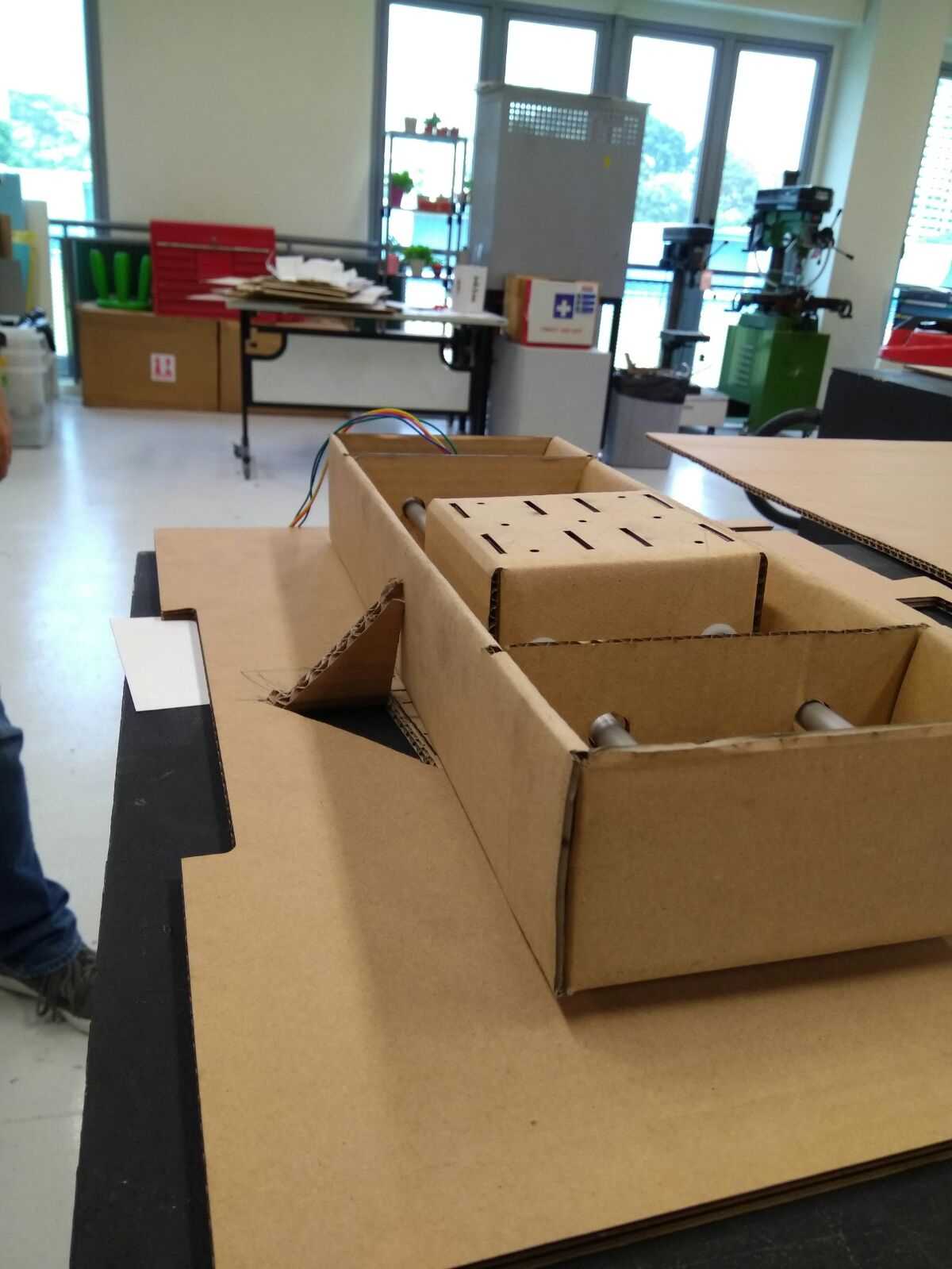
Cardboard Luggage Housing
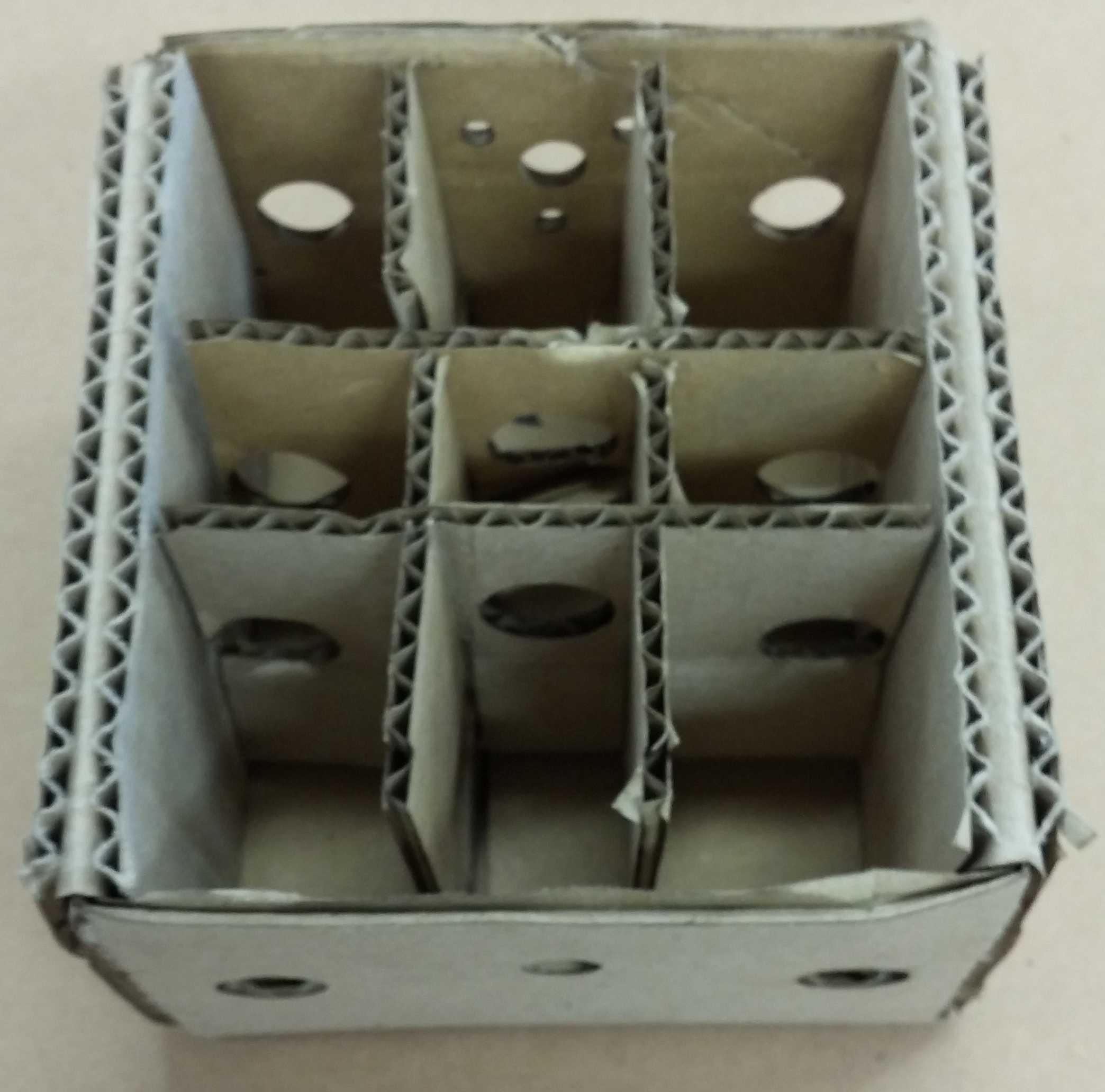
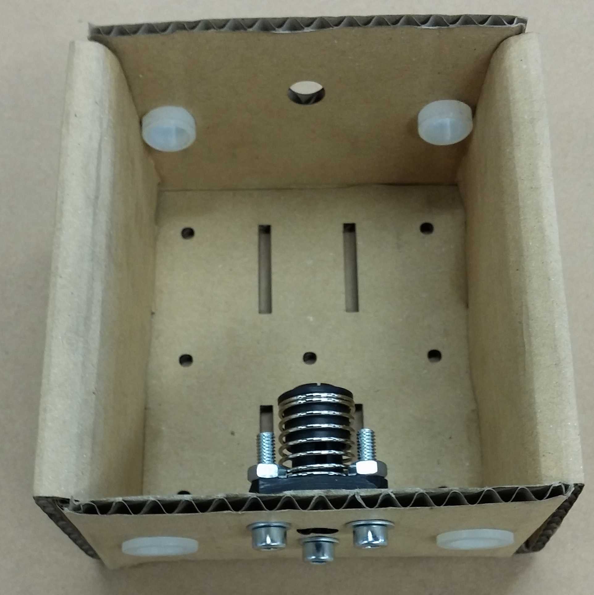
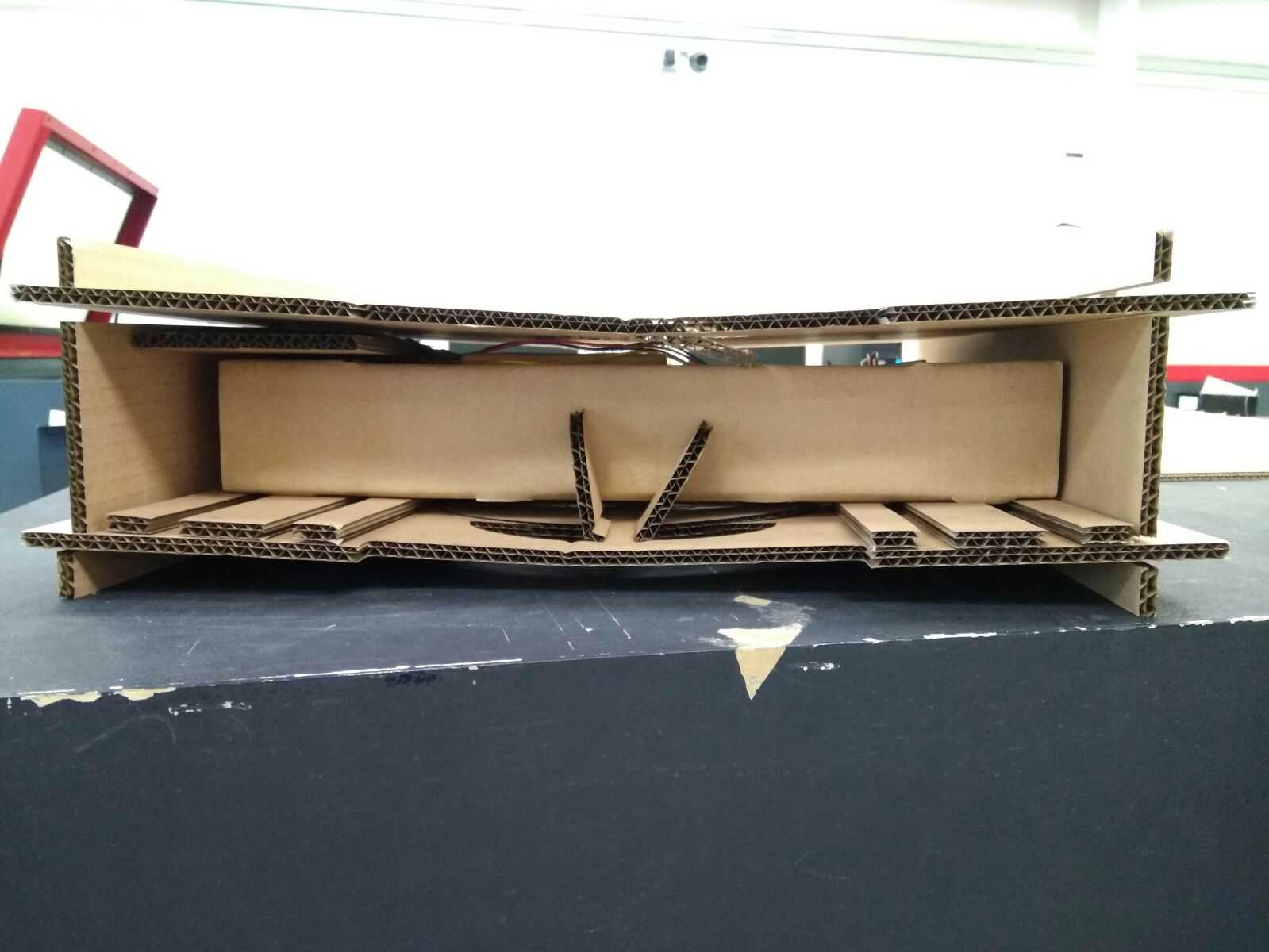
We make our project modular, therefore we also want to improve our design on making it portable too.
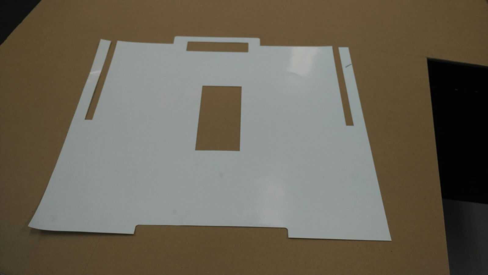
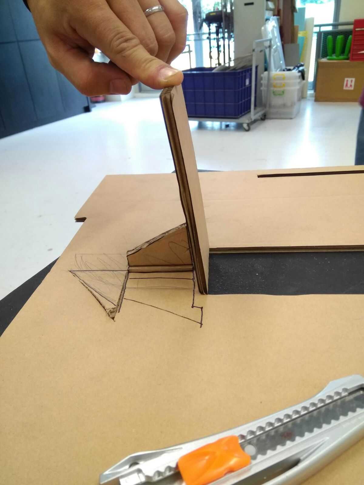
Basically, one of the module will be slotted into the hole in the middle of the luggage, supported by a tongue and a butterfly design wedge to support the weight of the frame & stage.
The images below is to show how we prototype the design.
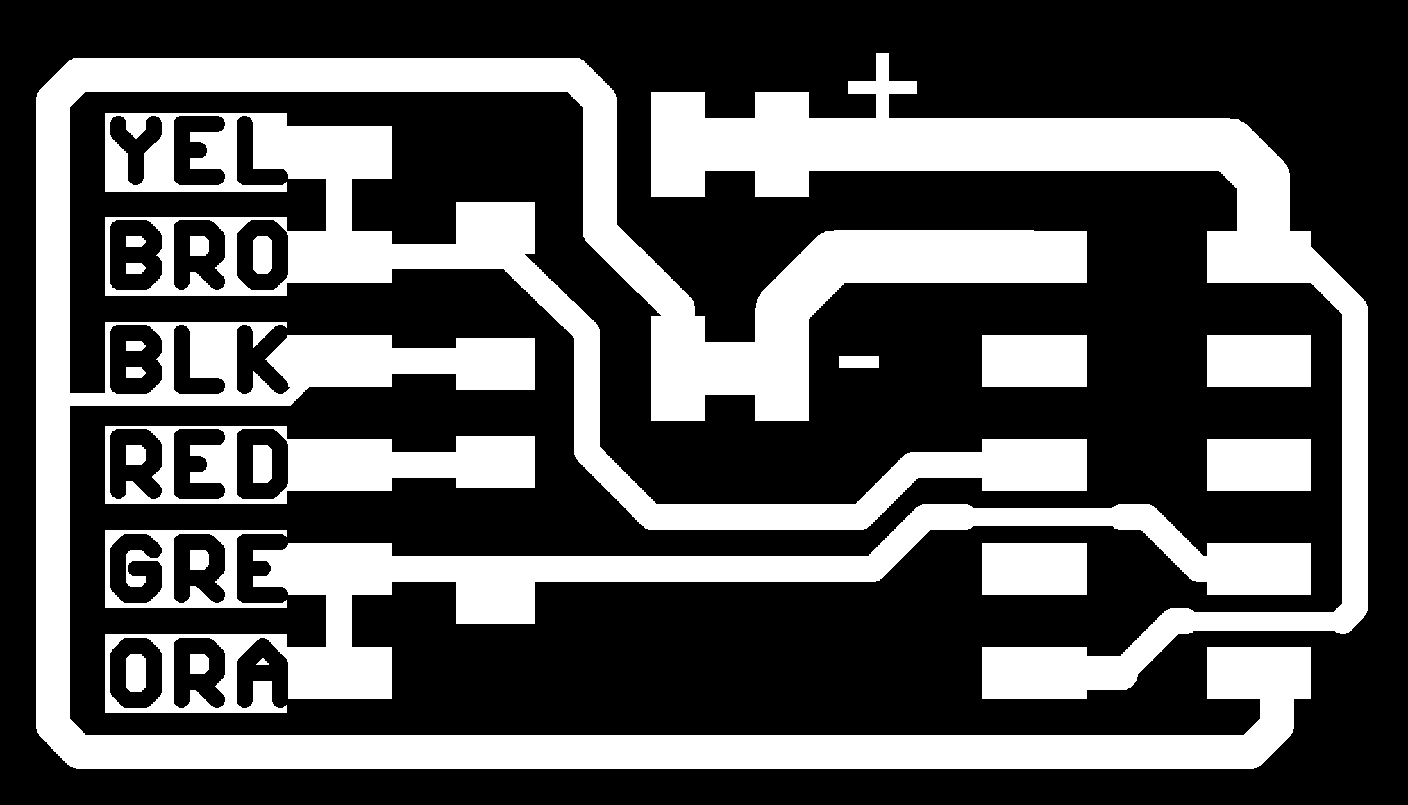
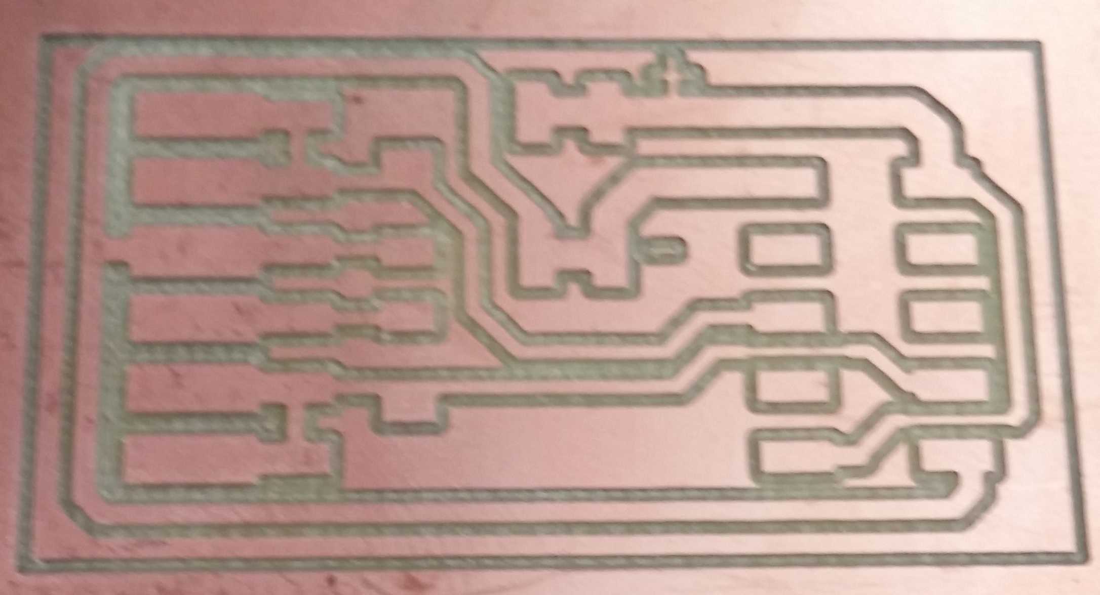
Make and Mill the Bridge Board
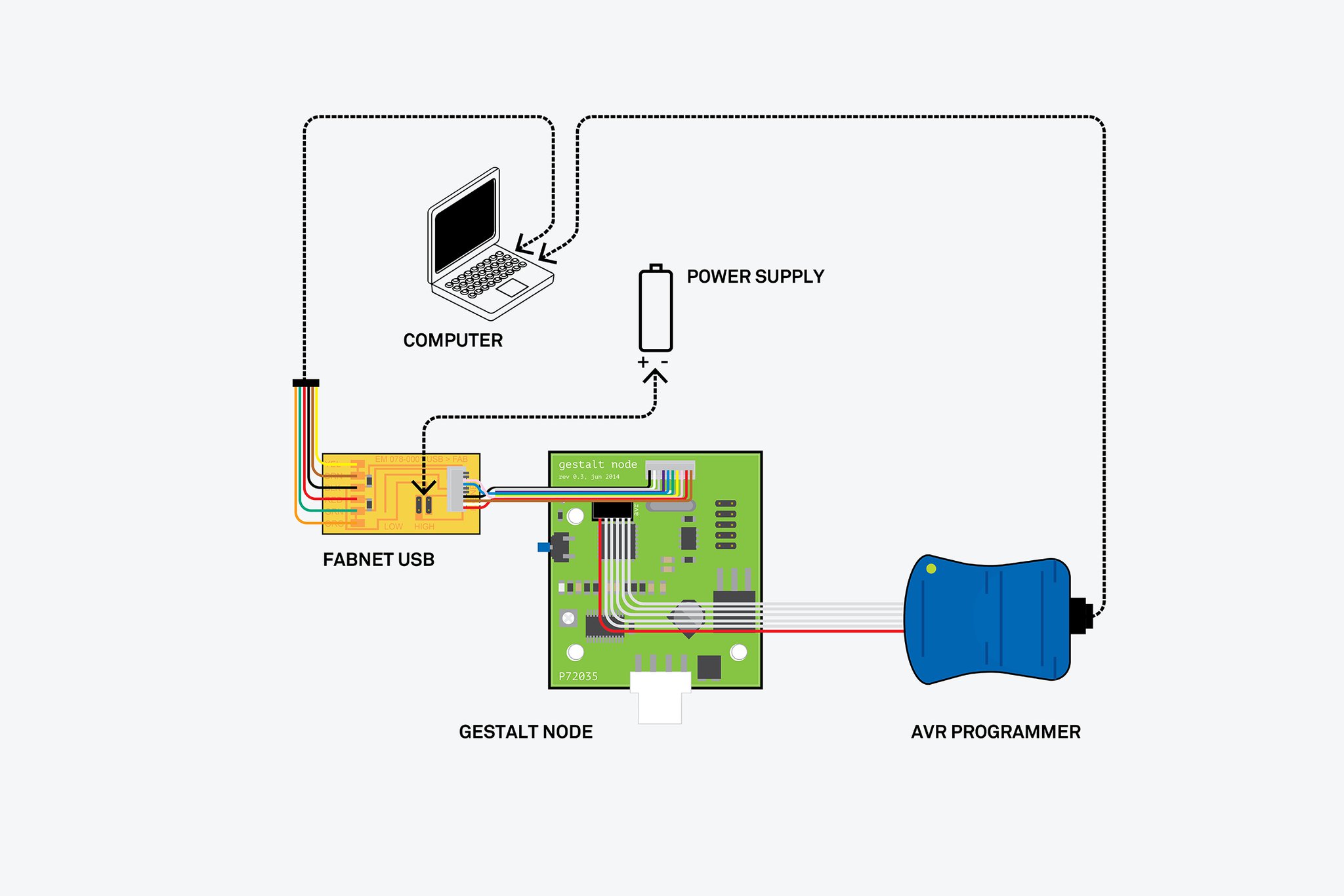
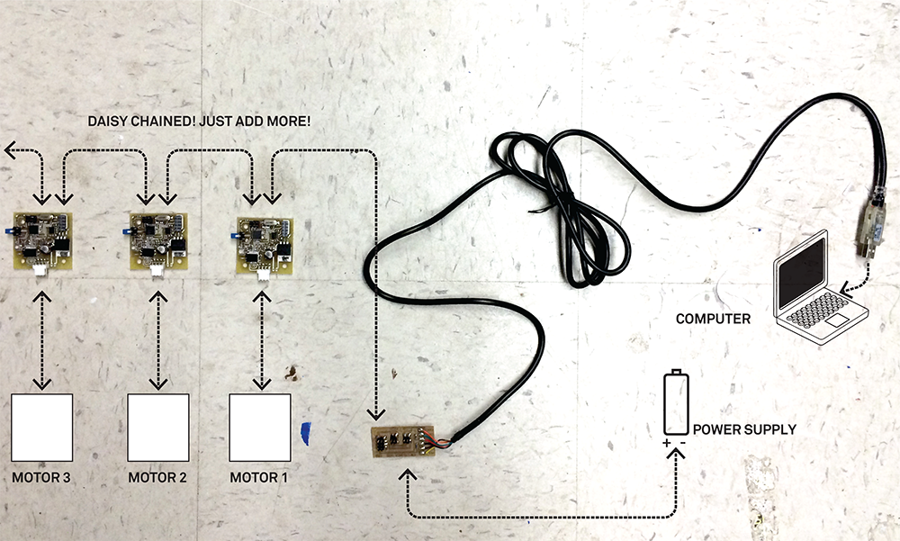
We need to mill and make the brige board that connect to the FABNET. The FabNet is a multi-drop network, meaning that multiple modules (a.k.a. nodes) share a single set of communication wires. Signaling is differential based on the RS-485 specification. Each node is assigned a four-byte IP address which uniquely identifies it over the network.
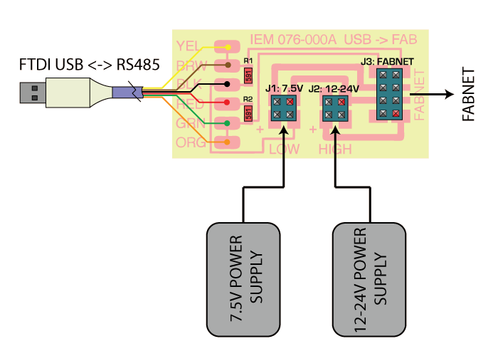
The bridge board is necessary as it will supply voltage to the cards, allow communication between the Fabnet and the computer. It's schematic and layout can be downloaded at this site.
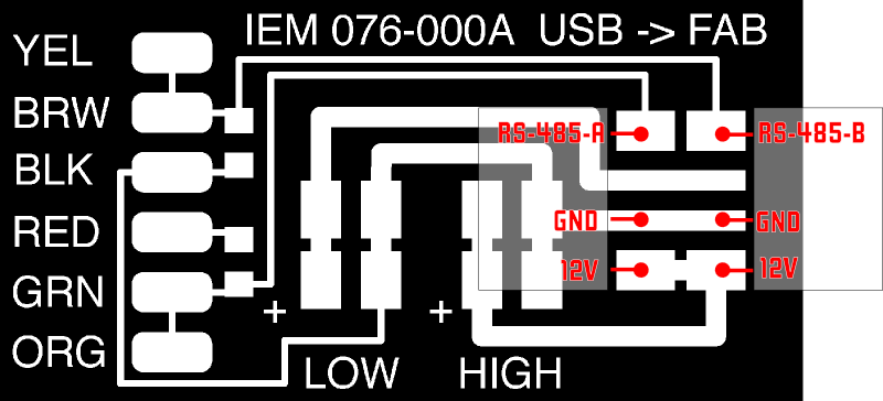
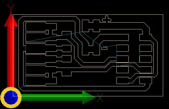
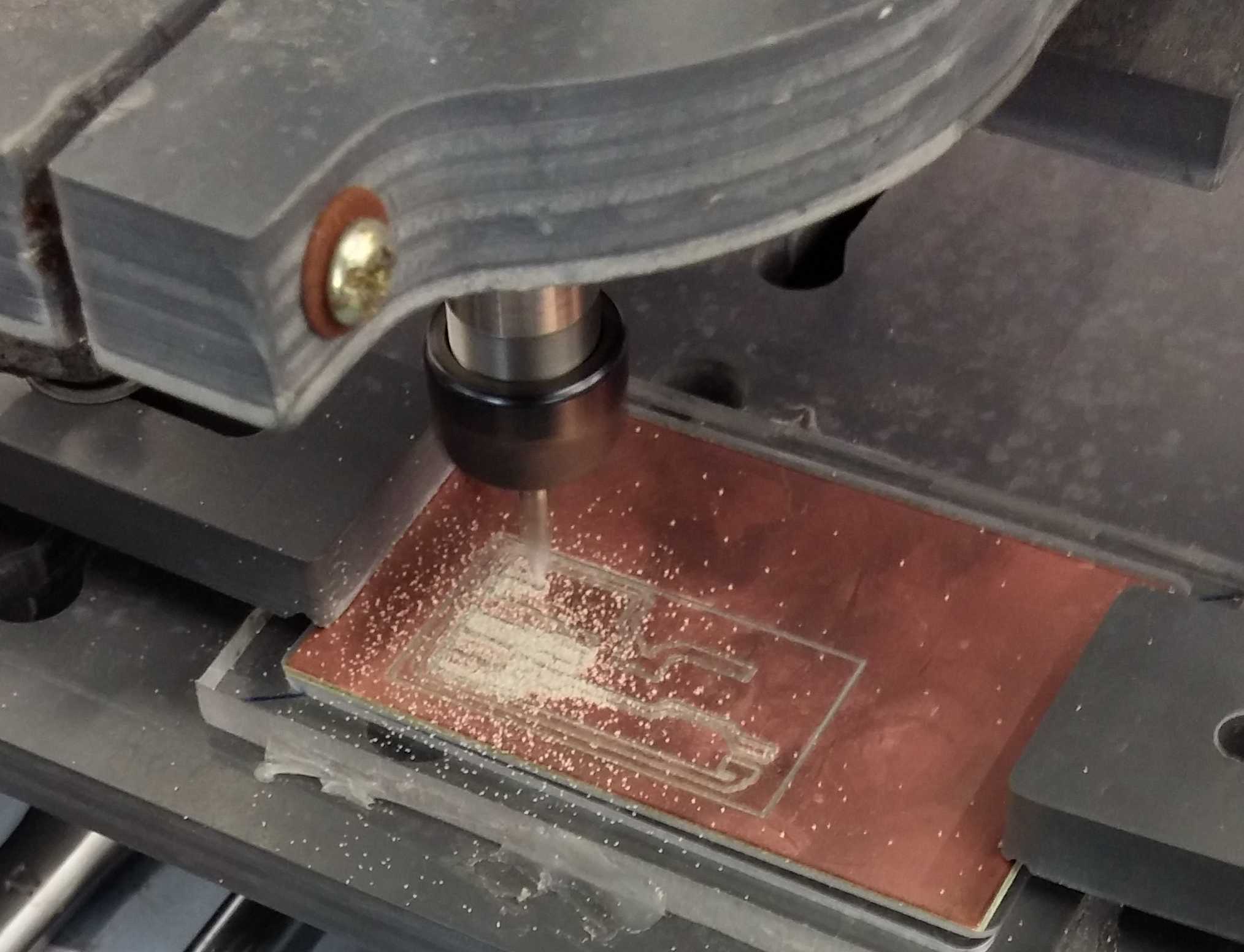
With the board layout, go to Eagle > Run ulp > Create *.etch file to be mill using the CNC USB Controller software comes with the milling machine PCB2020B.
After milling out the board, was told by local instructor to use the design by Bas instead as it allows you to use a straight through ribbon cable.
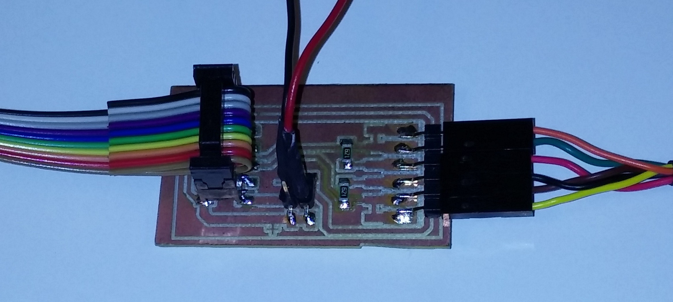
To make the board we need the following components
- One 2x5 pin connector
- 1 x 4 pin connector
- 2 x 600 Ohm resistors
- 1 x 6 pin connector
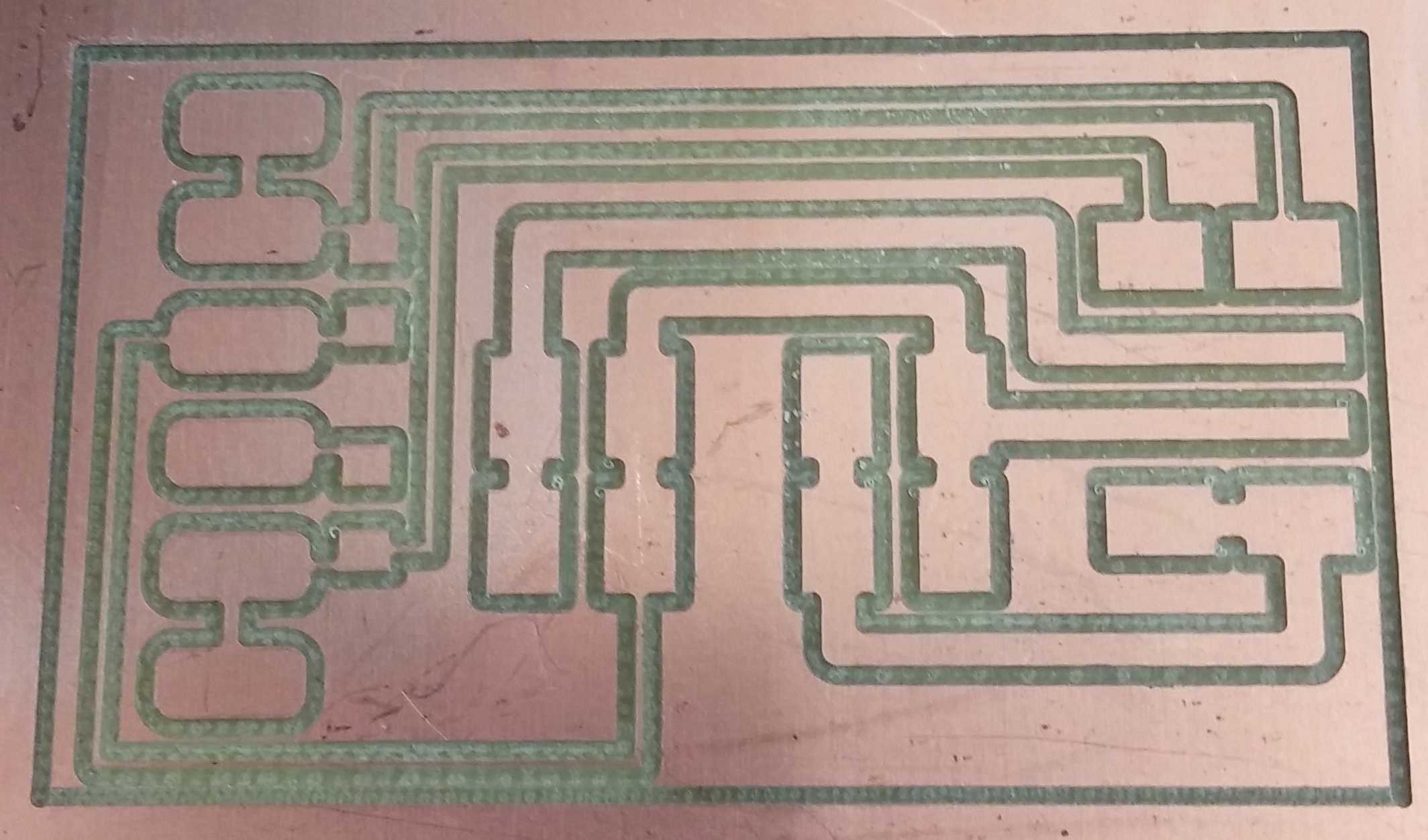
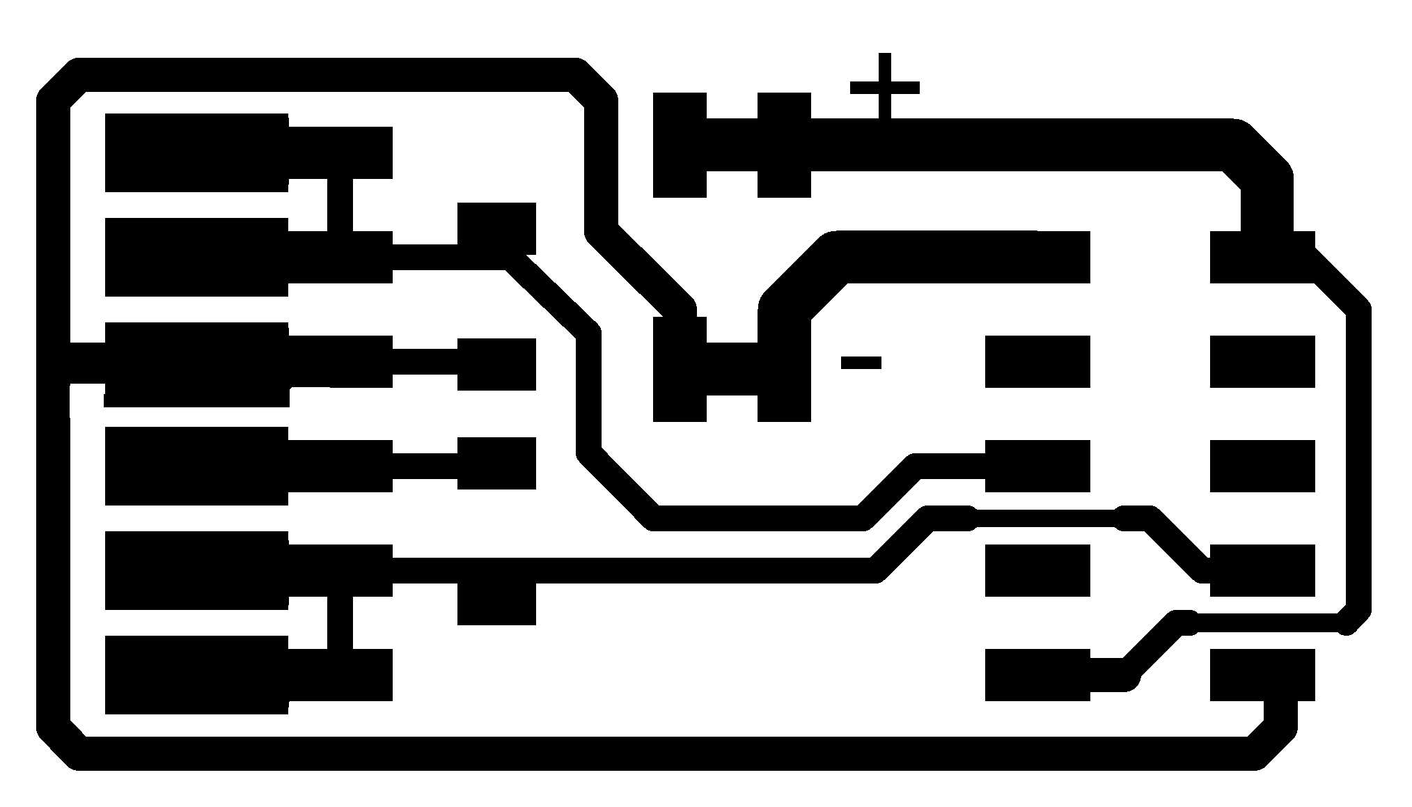
We made some modification by removing the text and reduce the track. Upon milling the board, proceed to solder the components onto the bridge board. Realise that the PADS on the board is too big and the components legs were too thin. This is especially so for the 2x5 Pin connectors. The connectors have to be placed in a such position whereby it doesnt create a short circuit between the GND and VCC. Have to re-work and resolder on the connectors a few times before getting it done.
With the mill board ready, proceed to stuff the board and connect up the FTDI cable, we are ready for the next step.
Explore the Gestalt Framework
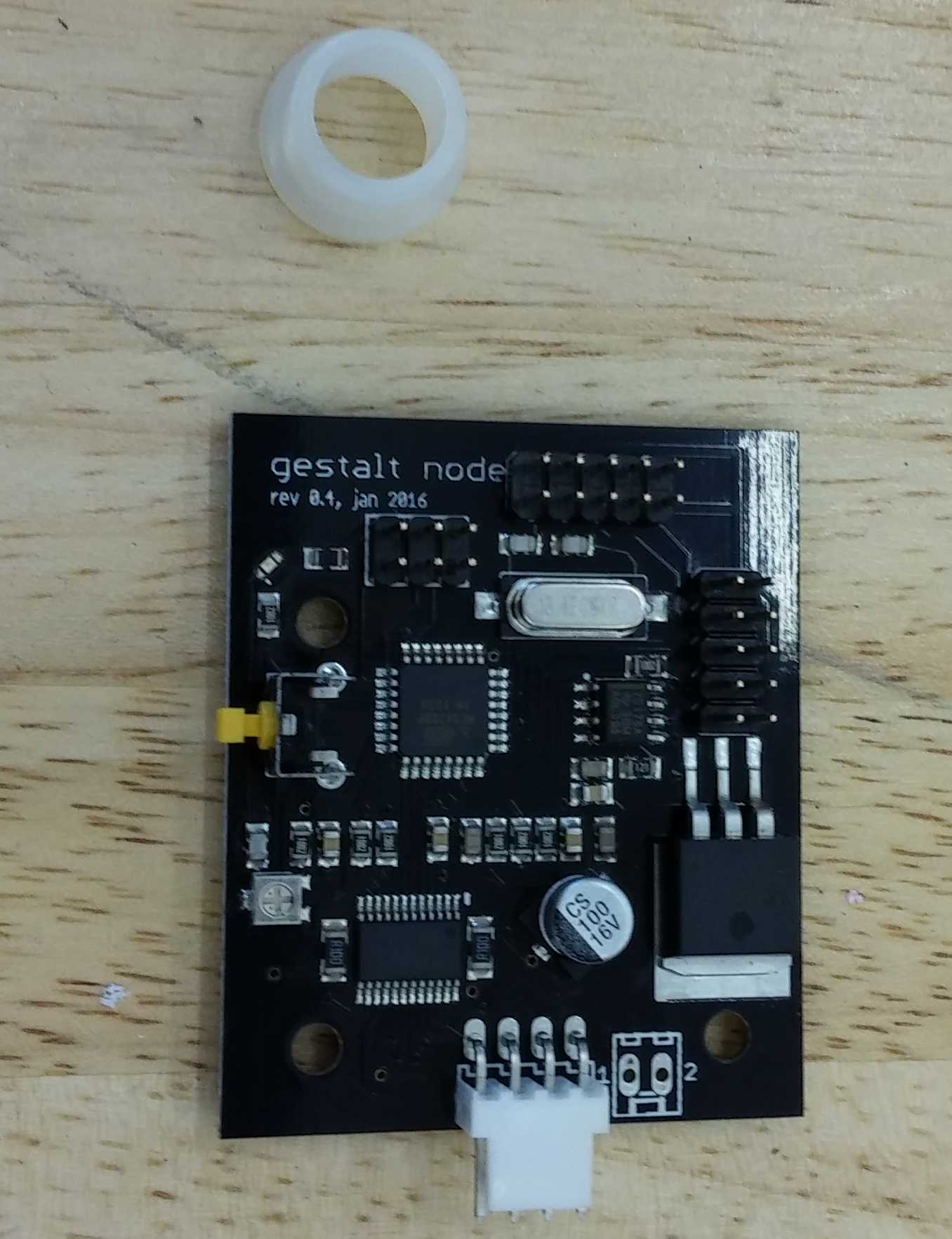
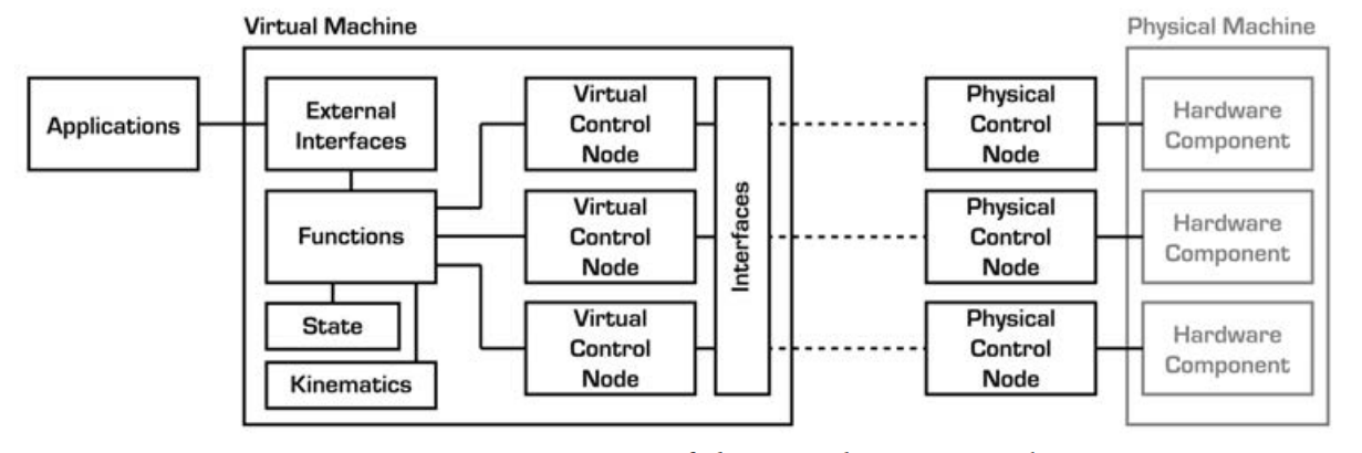
Gestalt is a framework for building controllers for automated tools. It comprised of an extensible collection of software modules that can be combined in many ways to quickly realize machine controllers. A physical machine comprises a number of electronic and electromechanical hardware components.
A series of physical control nodes provide low-level control of the machine components, and connect to the Gestalt virtual machine via either a direct connection or a network bus. Each physical control node is matched by a virtual node that exposes to the virtual machine the functions needed to control its specific hardware. The virtual machine additionally might contain kinematic definitions, memory of state (i.e. position), machine-level functions (e.g. to move the machine) and external interfaces through which user applications can control the machine. It enables you to import your machines as Python modules, and makes it easy to connect machines to browser-based user interfaces.
The following tutorial gives an idea for programming for Gestalt nodes.
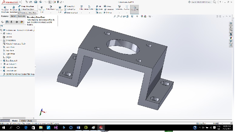
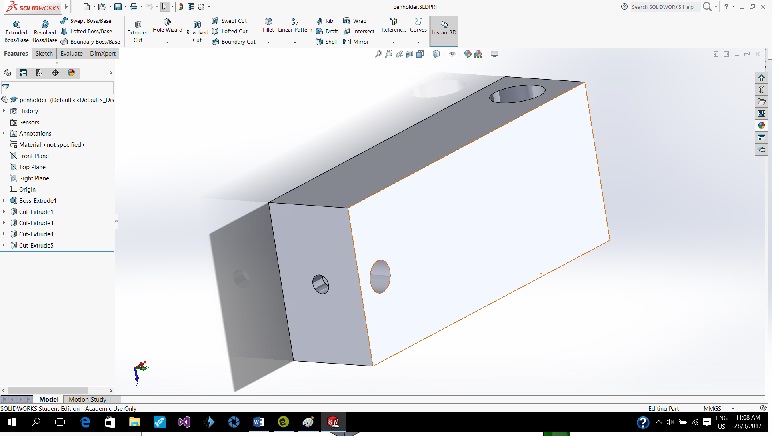
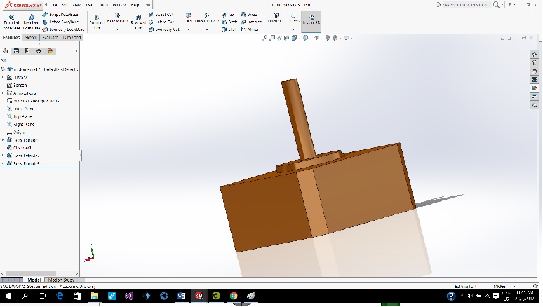
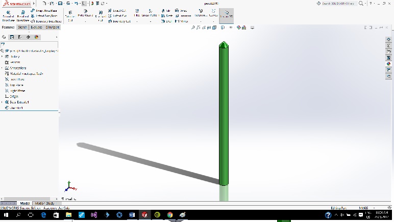
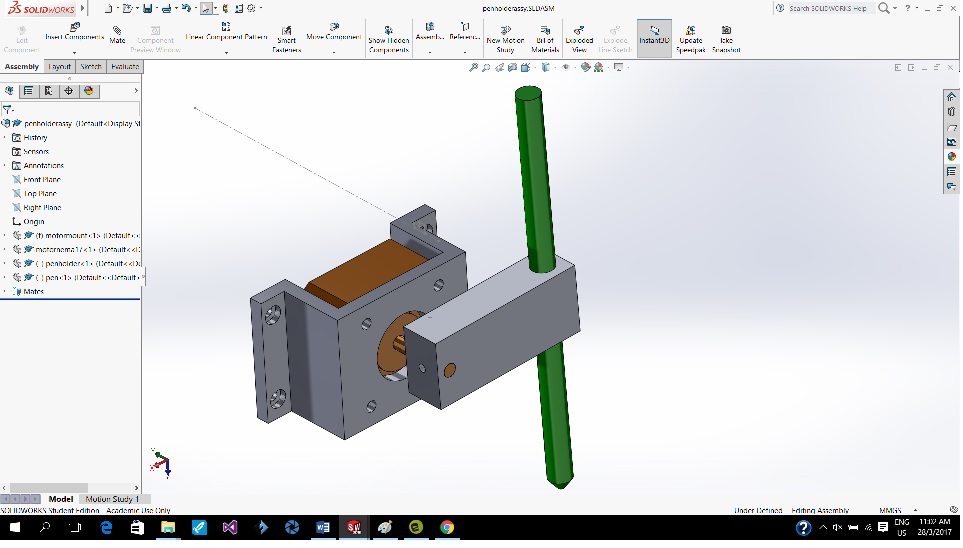
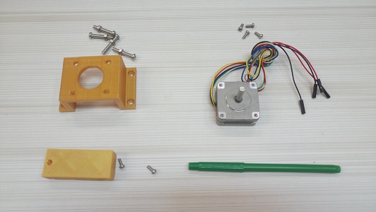
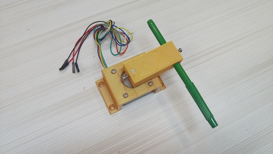
3D Design and Print the Pen Holder
The Z axis for our project would be the pen-holder. The design would be consist of the following parts:
- Stepper Motor Holder
- Pen Holder
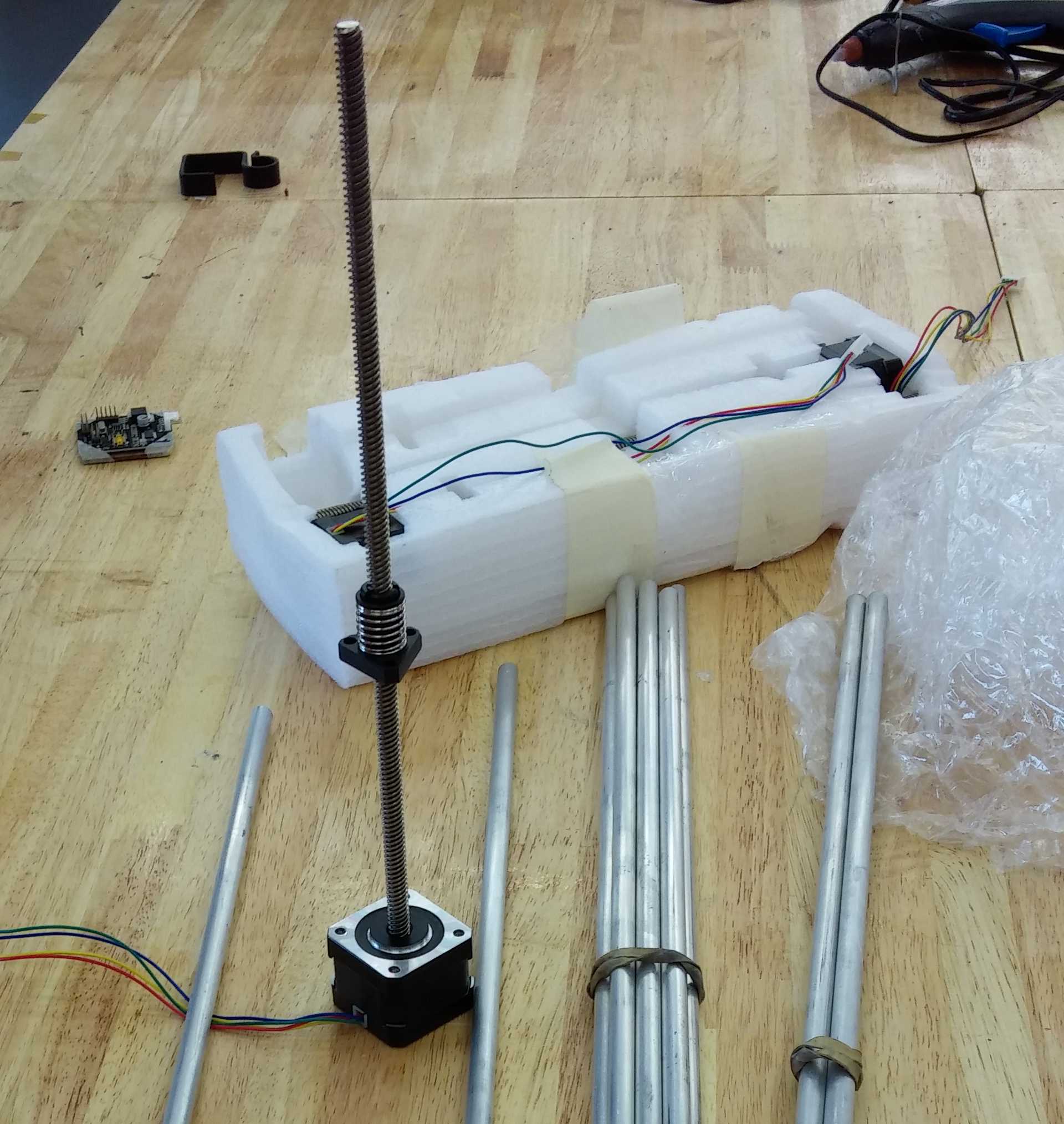
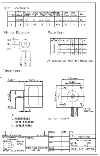
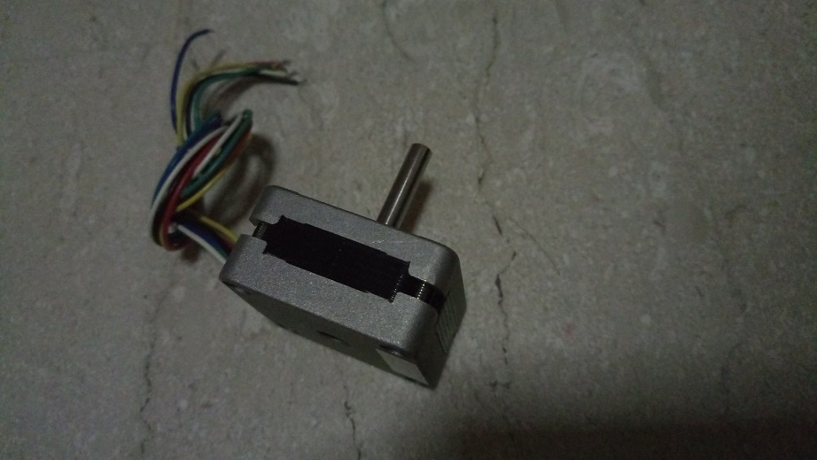
The design was done in Solidworks and parts was 3D printed. The MTM slide module's stepper will not be used because the lead screw cannot be removed. Instead, a normal NEMA stepper model FL39ST20 2 phase stepper will be used without the lead screw. The datasheet of FL39ST20 is shown below.
Connecting and Testing the Stepper Motor
With reference to class site and with the Fabnet board ready, a test on the stepper motor using single_node.py has been carried out.
Next, we try out hotbotplusz.py from pygestalt to figure out how the python code works with the Gestalt node and the FDTI and this is how it looks like initiating.
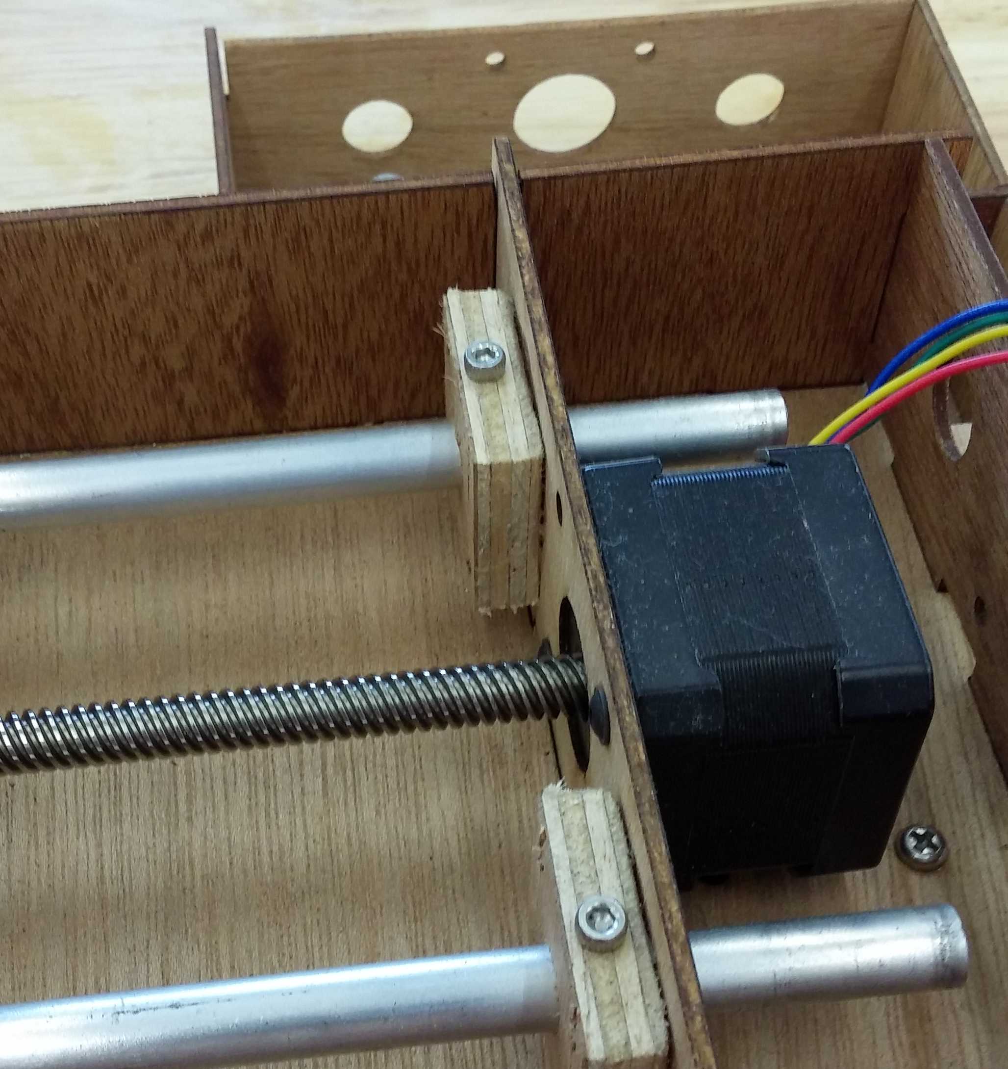
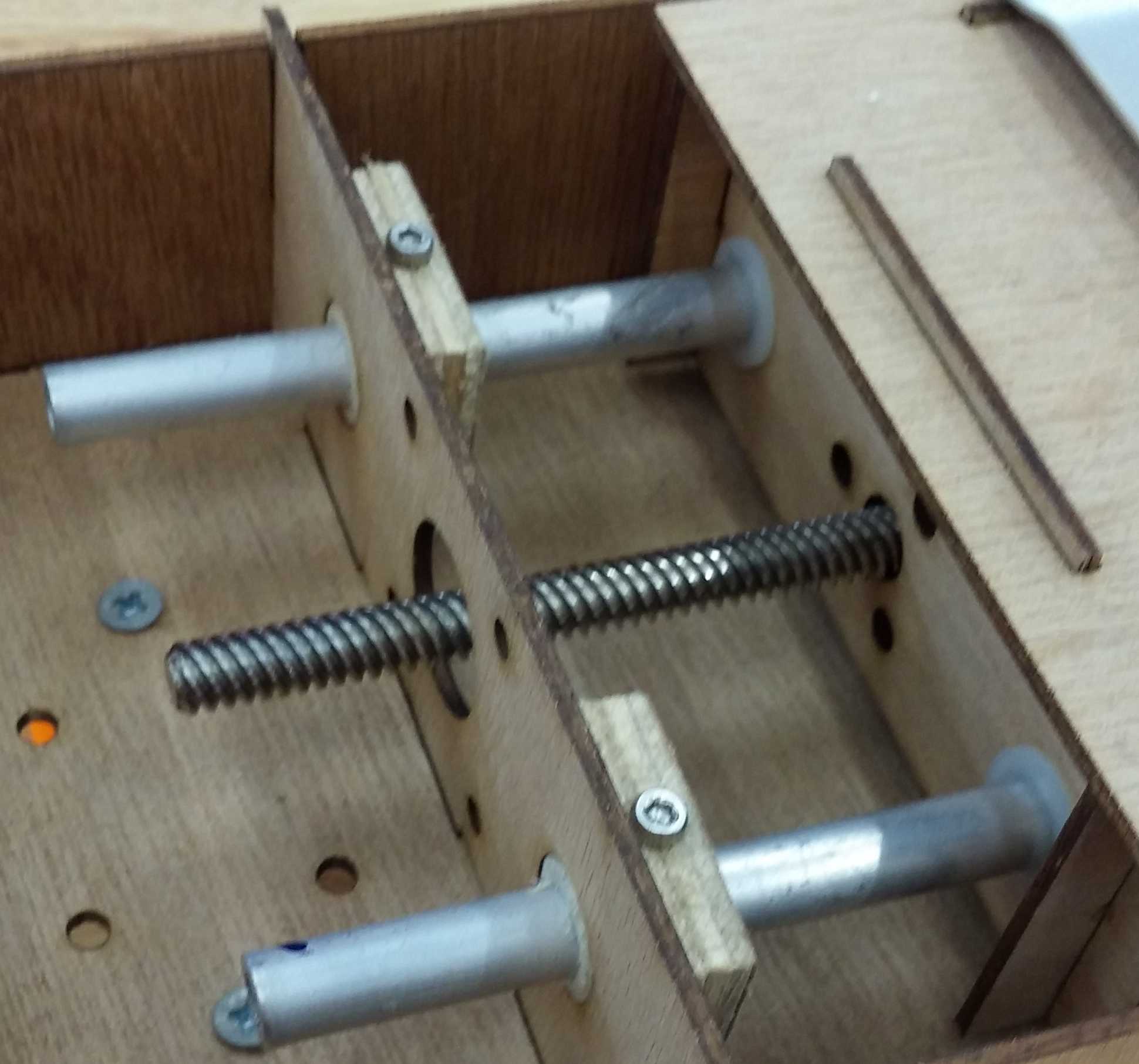
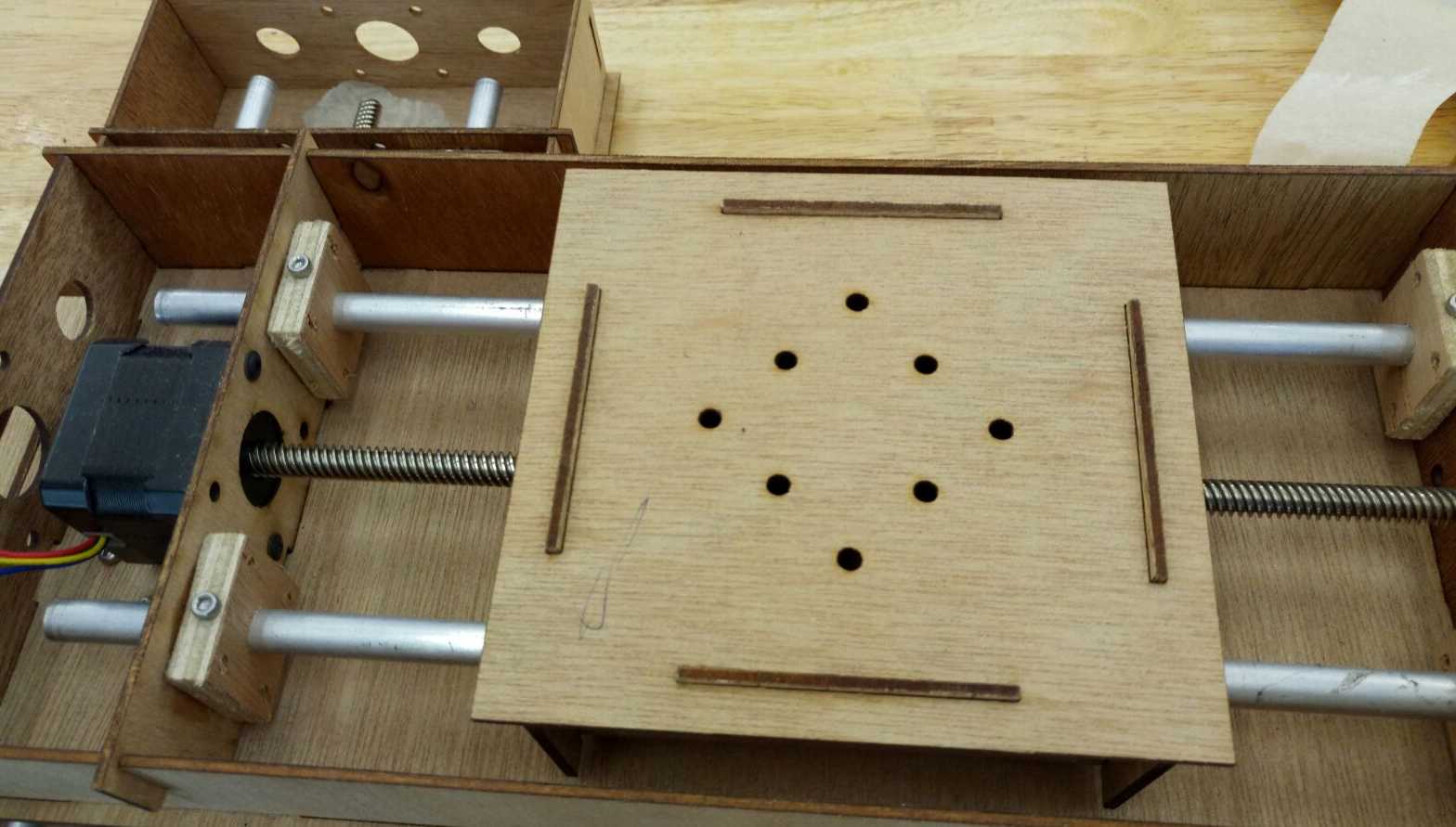
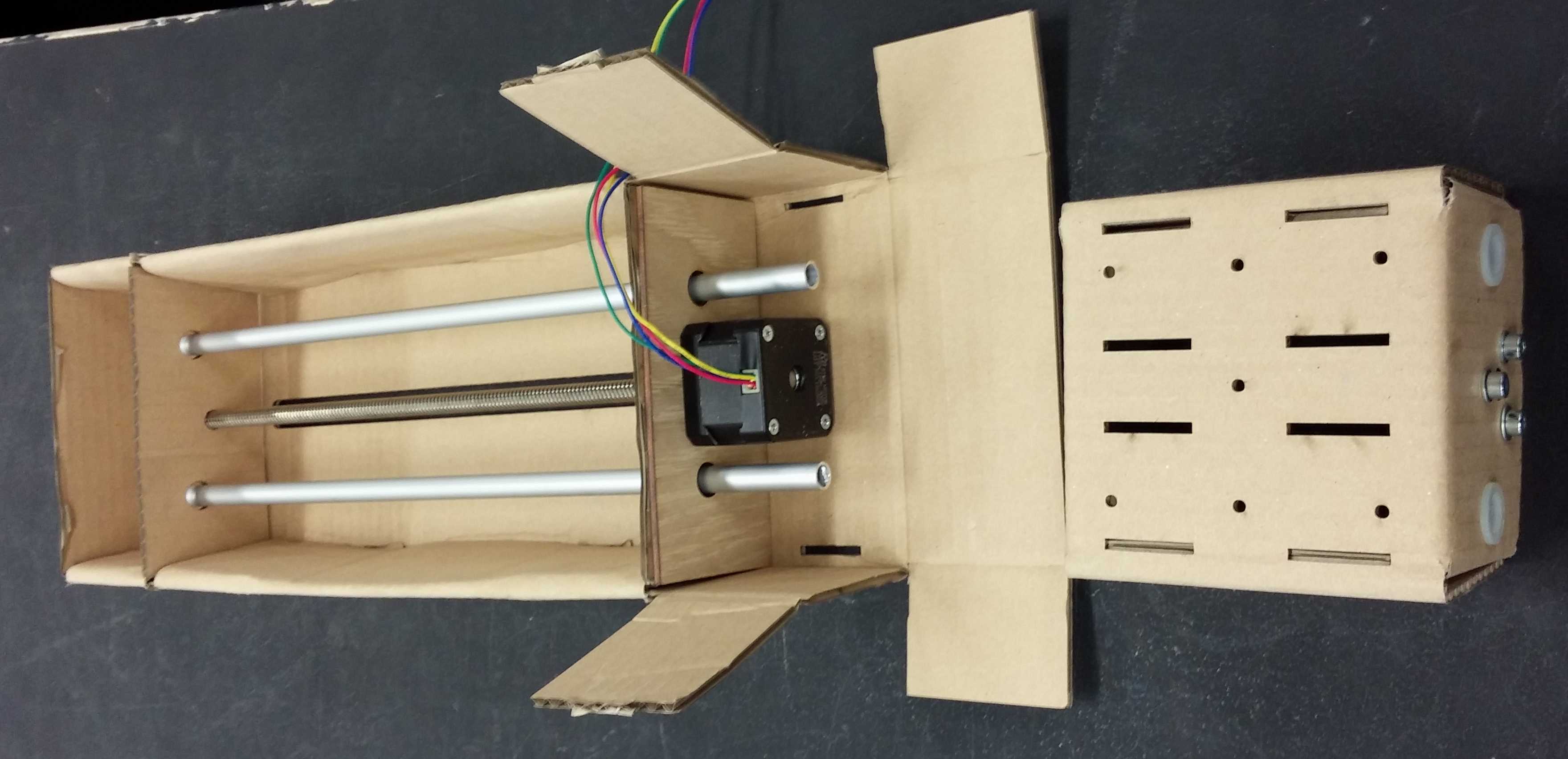
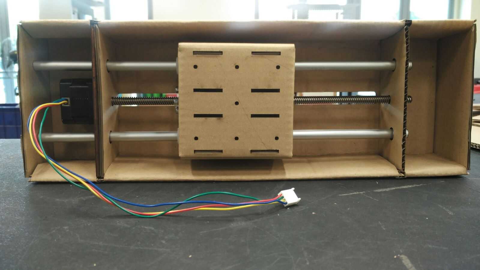
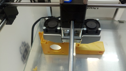
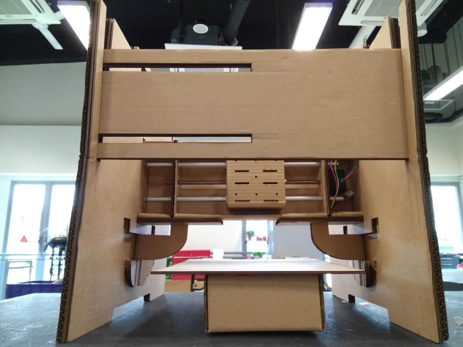
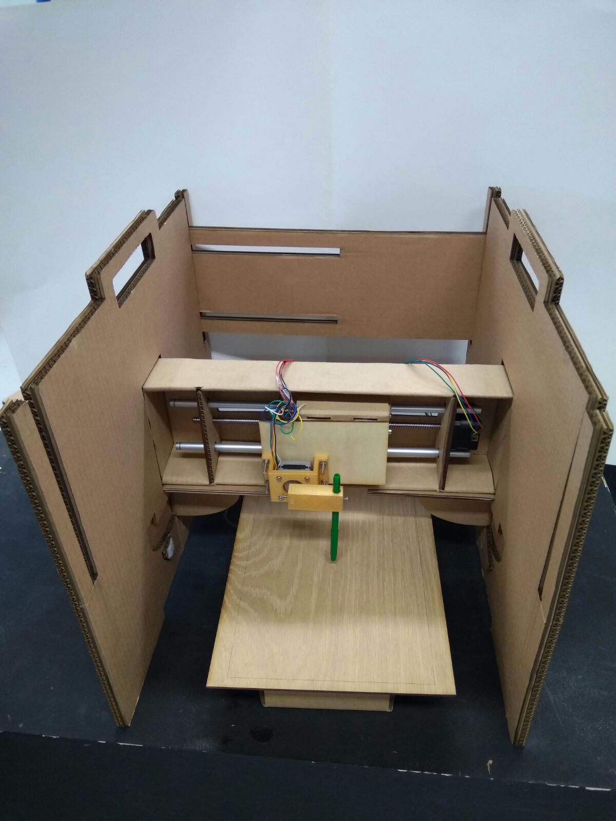
Assemble the Cardboard design housing with the Stepper Motor
With the testing on stepper motor done, proceed to do the full assembly and test out the mechanical assembly. After assembly, we need to use our hands to turn the gear thread rod to see if the the stage is moving up and down according.
If that works, it shows that our assembly is ok and ready to proceed on to make our project.
Our Thoughts
Instead of doing individually, we worked together as a group and discuss on how to tackle the design for our machine & making it modular even though it has to be documented separately as individual contribution. With that said, we also looked into figuring out how Python works and "talks" to the Gestalt node.
We also tried using plywood and realised that plywood is sturdy, but the slot is loose and not flexible enough for use to manipulate to make the stage and frame, therefore we were inspired by Nadya Peek's design.
Our decision to work together really pays off as we were helping each other discussing ideas and plan on the action to make our machine.
Hero Shot of our design
Downloads
Members
Teo Cher Kok
Soh Hong Guan
Foo Tiang Seih
Phay Ngiap Peng
Goh Chong Hao Louis
Return to top