Final Project: Design Journey
A summary of the planning steps for the final project can be found in week 17 assigment page. Here, I add the details of specific learnings in the design journey
Desgin Requirements
The design requirements of the filharmonic is sketched below. This is a first approximation based on the general outlines for the apparatus specified in ASTM standard 1876, the 'Standard Test Method for Dynamic Young's Modulus, Shear Modulus, and Poisson's Ratio by Impulse Excitation of Vibration'. There are numerous variations possible in the design. The following are the main design requirements (see ASTM 1876 for details):
1. An impulser (e.g. flexible polymer rod with metal ball to excite the sample)
2. Signal detector (e.g. contact transducer such as an accelerometer or non-contact transducer such as an acoustic microphone)
3. Electronic system (including a signal conditioner/amplifier, signal analyzer, and frequency readout device)
4. Support system that isolates the specimen from ambient vibrations while also being able to be adapted to control for sample modes of vibration (e.g. wire suspension)

This was the first illustration of the system to build, based on the description in the ASTM standard.
I now go into each of these components in detail, noting the design decisions.
1. Apparatus
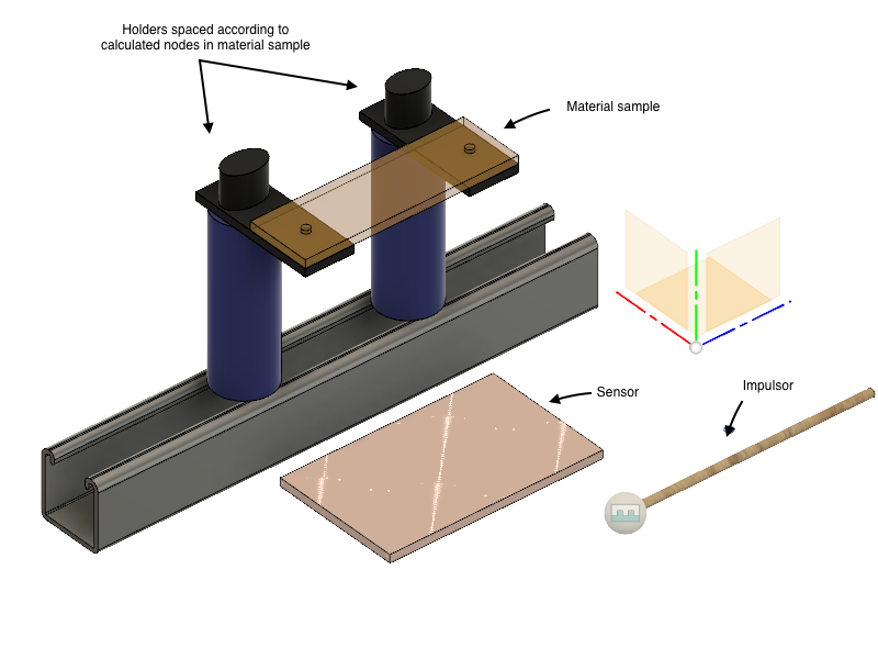
This is a prototype done in Fusion 360, with inspiration from a Xylophone. The impulsor is used to strike the sample, and the sensor picks up the vibration of the material In the current design, the signal is then send to a computer to be analyzed, and the elastic properties of the sample computed. The holders are designed so that you can vary the distance between them, to allow for samples of different sizes, as well as the holding of the sample at specific frequency nodes
However, I began researching existing apparatus examples, and I found that professional devices were much simpler. This is for good reason. The key thing you want to avoid is any interferring frequencies generated by the materials of the apparatus set up. Therefore, controlling unwanted movement in any of the apparatus is of utmost importance. I decided to go for the simplest option, similar to Buzz-omatic.
2. Electronics
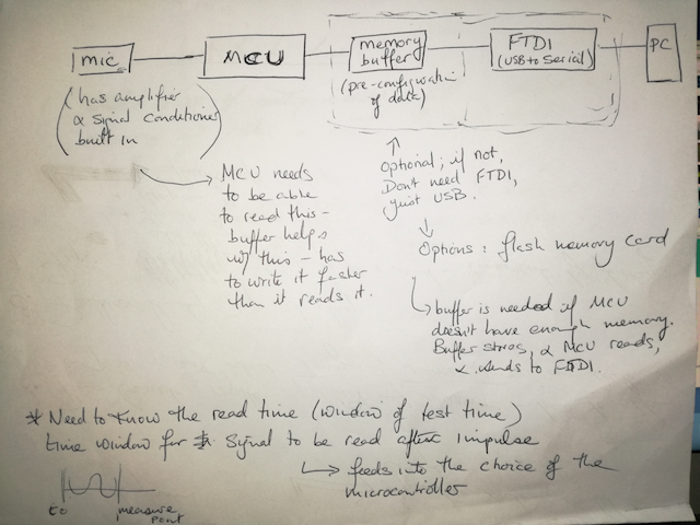
To review, the parts of the electronics specified in the ASTM standard are (1) signal detector, (2) signal conditioner/amplifier, (3) signal analyzer, and (4) frequency readout device. A general design of the electronics system is mapped as follows:
2.1. Input Signal:
One of the first critical design questions was to find the necessary range of frequencies that needed to be measured. I used the equation for determining elasticity specified in the ASTM standard, but instead of calculating elasticity, I calculated frequencies using standard elasticity values of example materials. I calculated frequencies for elastomer and thermoplastics, in addition to a ceramic, wood and metal. The spreadsheet with the file is found here.A snapshot of the table is below.
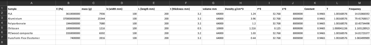
Based on these calculations I determined I needed a sensor to cover the range of 0-100 Hz, with an elastomer being the lowest resonance frequency, and aluminium being the highest.
We then ordered a few sensors to experiment with from Mouser: MEMS Microphone., Digital Zero Height SiSonic, and this Output Digital Microphone.
3. Application (signal analysis and read-out device)
The components of programming my application are:
The sample dimensions are covered in the section below, and more detail on the application is found on the Week 16 page. Here I go into detail on the learning behind analyzing the signal from the microphone by way of a Fast Fourier Transform (FFT) to enable the finding of the resonant frequency (the key ingredient for finding elastic modulus using this method).
Analysis: Fast Fourier Transform
When the signal is read, it needs to go through a Fast Fourier Transform in order for the resonant frequency to be found. I had to learn what a FFT was really doing, and it turns out to be fundamental to signal analysis in the engineering sciences and beyond. I found an extremely good tutorial explaining it using regular language, building up the understanding layer by layer. The original article detailing the FFT algorithm can be found here
The key insight to my understanding was the idea of the FFT ‘decomposing’ a signal (with a time dimension) into its frequency parts (it’s specific recipe). It does this by applying mathematical filters to the signal, to capture the various wave frequencies Each frequency in the signal interferes with each other and either causes constructive or destructive interference (like waves in a pool). When they add to one another you get frequency spikes at certain time intervals. These spikes, merged together, can be thought of the recipe for the entire signal. For the purpose of determining the resonant frequency of a material, these frequency spikes are useful, as we can interpret the major one as the ‘resonant frequency’, and the others as contributing frequencies. What I'm seeking to do is measure the first, 'resonant' frequency. The other contributing frequencies are called harmonics (a fimilar term when you think of guitar strings).
I designed the application in PyQt and programmed it in python3; here is an image of the application mock up. More can be found in week 16: interface and application programming
Computation of Young’s Modulus
This is a straightforward calculation, based on all the variables inputed to the system. Image: “fundamental flexure resonant frequency of a rectangular bar”

4. Sample preparation
Mass Weighing scale Dimensions Simple use of a ruler! Samples: Acrylic Aluminium5. Set up
The key to setting up the eTester is correctly placing the sample on the balance points (either foam strips or knife edges) at the required nodes. As specified in the ASTM standard (see image below), for the measurement of fundamental flexural resonant frequency (in-plane and out of plane).
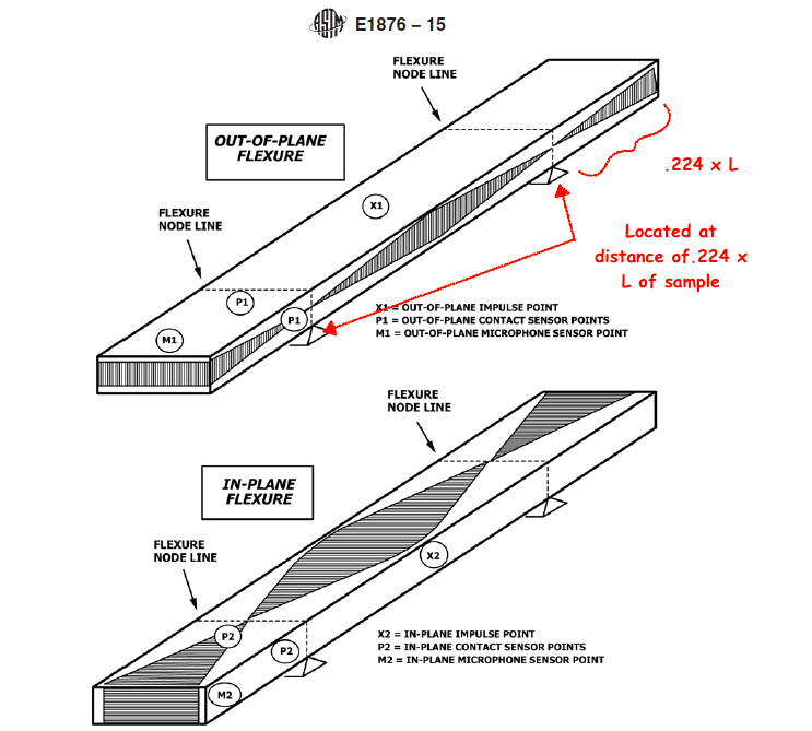
For the rectangular samples, the supports should be placed under the sample at .224 x L. This lines up with the nodes of the sample, where the resonant frequency behaves as a 'standing wave' in between that can be measured by the microphone.
Here are the project design files:
System schematic Apparatus design