FabAcademy2017 - Projects
Computer-controlled machining
March 08, 2017 - Week#7
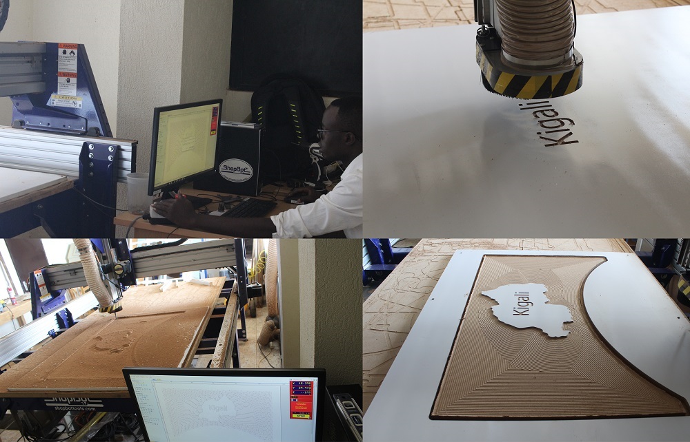
I always feared using Shopbot, I don't know whether it is because of its big size or the loud noise it makes. I finally learned how to use it, but I still have respect for it.
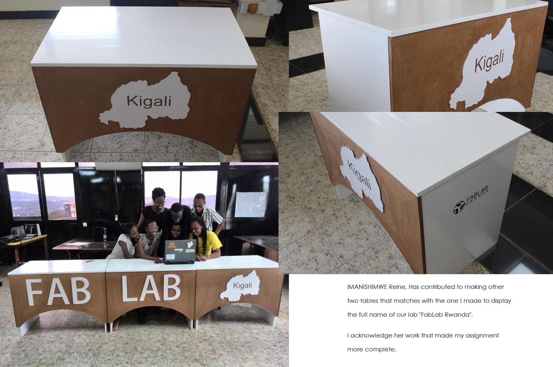
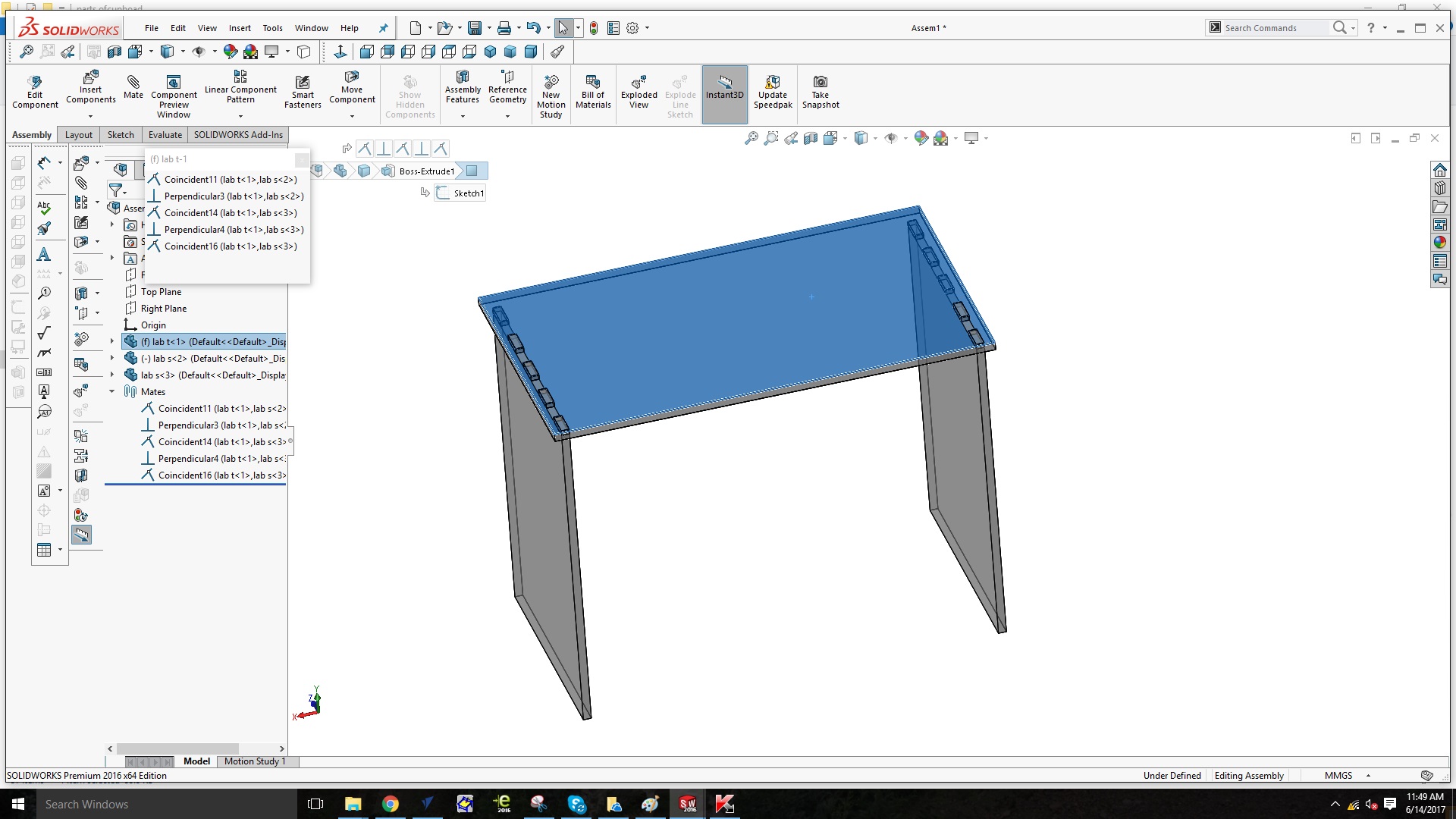
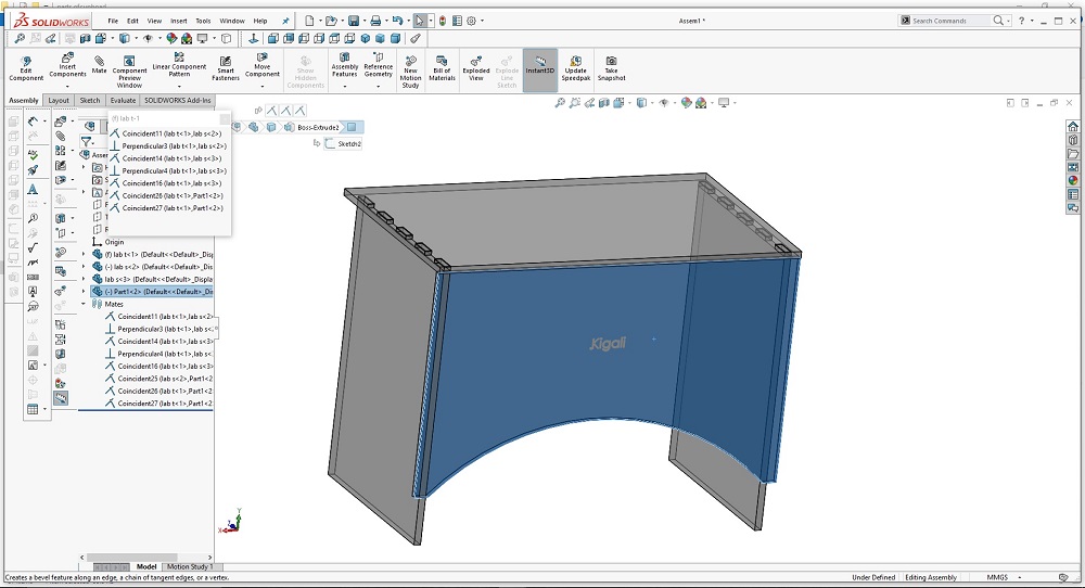
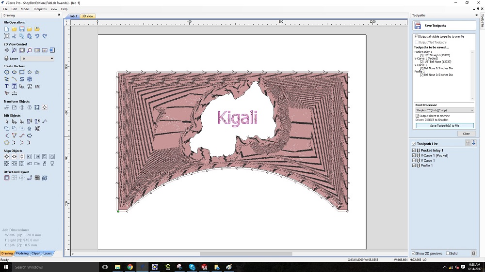
I started making a design for my computer controlled machining assignment designing a table that has a map of Rwanda on the front of it. Here I have shown how I made it.
It is a simple but nice and clear design, my table has three sides, the front side has a map of Rwanda designed on it not in Solidworks but in Vcarve. The table, is assembled buy Joints and screws.
The process of production to demonstrate correct workflows with Shopbot
Step 1: Putting the Wood Piece
First wear safety glasses and closed-toe shoes
1. Log in to your shoptbot computer.
2. Open the program “Vcarve Pro” (This is the one we use at our Fab Lab)
3. Go to File:Open to open your DXF or DWG file.
4. On Job Setup screen:
Units:Inches; Size:The size of your stock(x is the long axis on the machine. This is marked on the aluminum inside rail of the Shopbot for reference); Material: Z-zero dot should be on the top of the part. Measure the thickness of your stock with calipers and input it as the thickness. Don’t trust the manufacturer on material thickness ; XY Origin Position: This is a user preference, we’ll use the bottom left corner. Turn off “Use origin offset.” If your drawing and settings aren’t just right, this can cause the machine to try cutting in places you don’t want it to; Data Scaling: You have the option to click “Center data in job” to easily center your part, or you can do this manually in a later step. And click OK at the bottom.
Step 2: Initial Startup
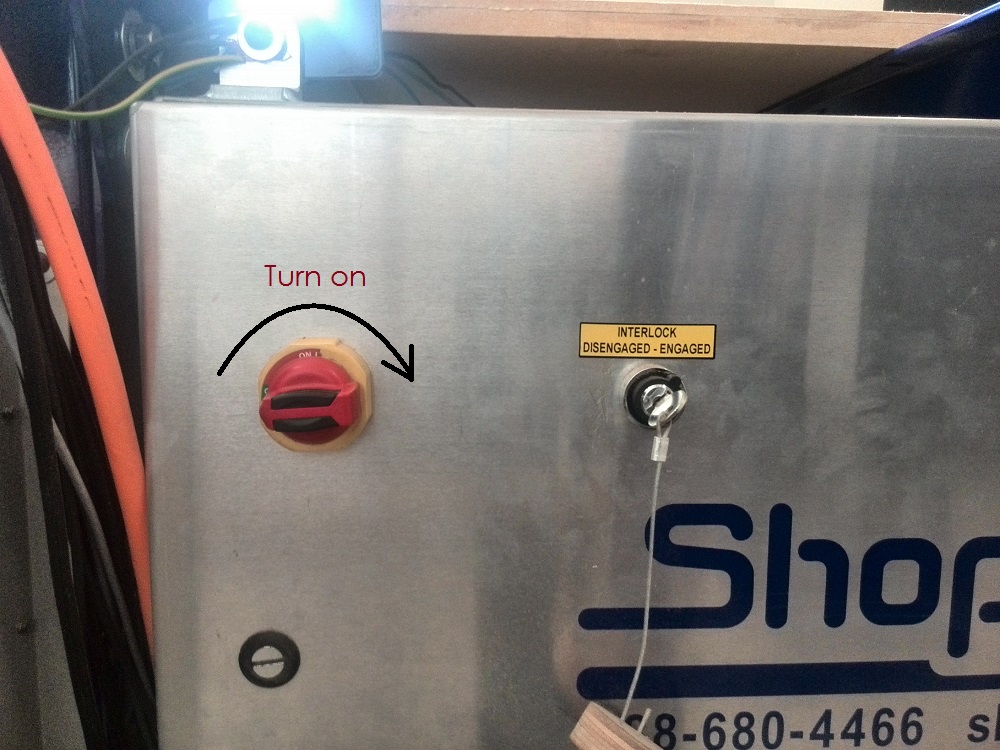
Turn on the power switch to the machine according to your model and placement.
1. Make sure the spindle key is engaged.
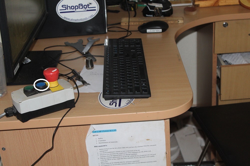
2. Release all emergency stops.
3. Launch the Shop Bot software on the computer attached to the machine.
4. Go to Cuts in the menu bar and select the spindle warm up routine.
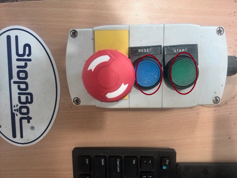
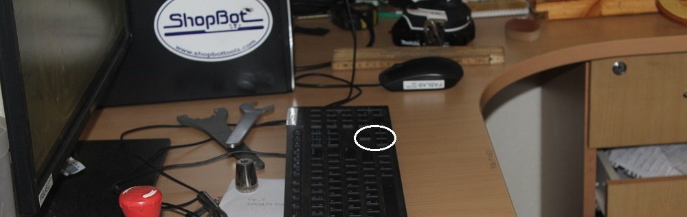
5. Before pressing OK on the next prompt start the spindle by pressing the green button.
And this should start the spindle warm up routine. If there is an error, press the reset button which is the blue switch and try again. This sometimes happens due to the emergency stops being engaged.
Step 3: Putting the Wood Piece
Show All Items Next step is to secure your wood piece. So basically you need to secure you wood down to the CNC bed with screws such that its corner is a bit offset from the end point of the machine.
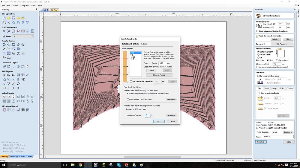
Step 4: Adding Tool Paths
Next you will need to add tool paths for each continuous line on your drawing. This might be different in every software so refer to your softwares tutorials.
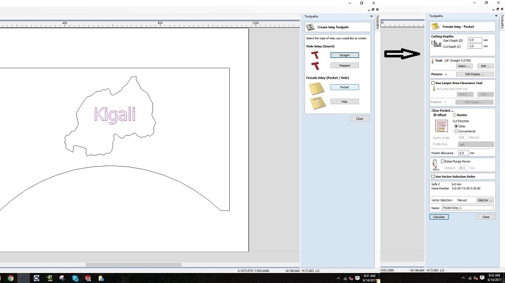
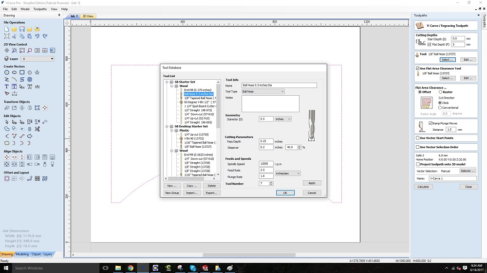
On the upper right corner, select add tool paths. Select on the line and then choose the type of cut you want to do. Next you will select parameters for each cut including the cut depth and tool. Tool is the bit you will use to make that cut. You will select a tool from the saved tools and select tool diameter that you are going to use.
Step 5: Saving Tool Paths
Next you will have to save your tool paths to a file that the shop bot software can read. Click on the save icon on the tool paths bar. Select all the tool paths by checking them. Save the tool path file
I first had to set up the machine and choose tools to use. For this table I made, I used two different tools.
The tool that was 1/8 inches in Diameter
And another one that was 1/5 inches in Diameter
Step 6: Zero-ing the Shop Bot
Next we need to zero down the shop bot so it knows where it is.
1. First go to the cuts menu on the shop bot software and select x y home using prox switches.
2. Then open the move panel and use the key board to move the gantry to a accessible position to install the first bit. 3. See what bit you will be using first and then use the spindle wrench and collet to attach the bit.
4. Next use the keyboard to align the bit with the origin of your piece based on your selection when setting it up.
5. Use the fixed option below the direction keys in the move panel to make fixed increments movements. It will help to zero it to the origin. 6. Be careful not to make the bit touch the piece.
7. Then go to the zero menu and click zero x and y
8. Next you will need to zero the x axis on top of the work piece.
9. Use the keyboard to move the gantry over the work piece.
10. Place the zeroing plate below the bit and make sure its wire is attached.
11. In the cuts menu select zero z axis using zeroing plate.
12. Click ok and allow the Shop Bot to move down to zero the z axis.
Step 7: Running the Part
Now you are finally ready to do some cutting.
1. Load your tool path file into the shop bot software and and click start.
2. Read and enter the prompts about zero-ing if they appear.
3. When the final prompt to start the spindle appears, you should attach your shroud around the router and turn on your dust collection system.
4. Start the spindle before clicking ok.
5. Click ok and then keep you hand on the emergency stop. If the shop bot does something unexpected, stop it and recheck everything.
6. Otherwise let the shop bot do its thing.

7. When its time for the next bit, the shop bot will stop and ask you if the next bit is in place.
8. Press no and then move the gantry if you have to but be careful not to stuck the program as it will ruin your progress.
9. Change the bit and press ok on the prompt.
10. Then you will repeat the z zero process using the plate.
11. Move the gantry over the piece when prompted to and zero the z plate.
Step 8: Removal and Cleanup
Once you are done, move the gantry away from the piece and unscrew your part. Use a saw to cutout the pieces and sand the tabs down. Make sure to clean up all the saw dust because its not good to have dust get accumulated in the gears and sliders. Then proper shut down procedure is to turn off the machine, disengage the spindle key and press in the emergency stops.
Then, I ran the engraving programme on the machine, and after that, I had to change the tool, and put the one with 1/5 inches to cut the material.
And finally the table was made. On the photo below you will see some members in FabLab Rwanda sitting on the table enjoying the new tables made in FabLab Rwanda For FabLab Members to have more wonderful working space. It was a great Idea with IMANISHIMWE Reine who used the same design and make other two tables which complemented mine to form the name "FabLab Rwanda".