FabAcademy2017 - Projects
Computer-controlled cutting
February 08, 2017 - Week#3
Laser cutting
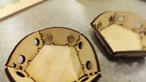
Computer controlled cutting is one of the most interesting computer controlled processes. When you have designed a good and complicated shape you are always looking forward to see how the result will be after assembling. For me, I designed one shape that when assembled becomes a stand for small stuff. Here are the steps I passed through parametrically designing my files.
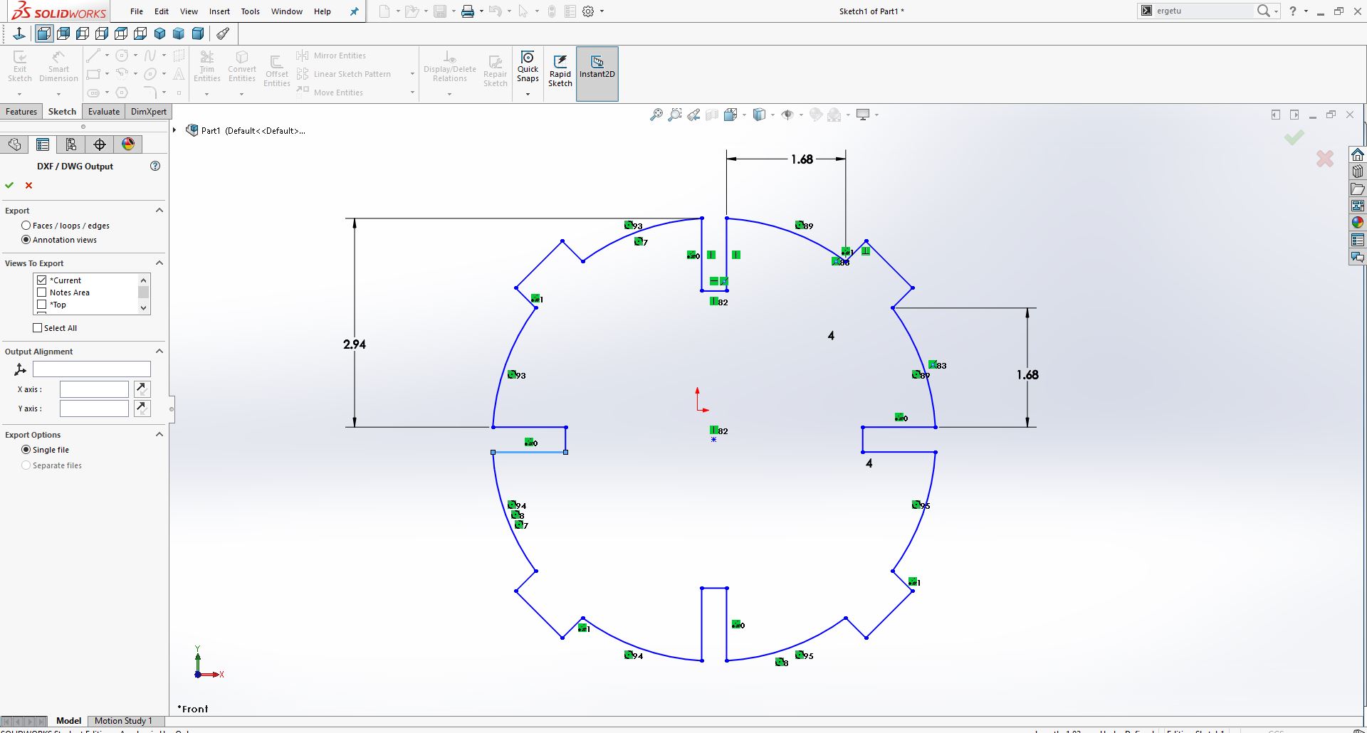
The Parametric Solid Modelling Process
To make a parametric solid model it stars with a sketch at the approximate size and shape of the part or feature to create to change the size and shape of the geometry, dimensions can be added later. While a parametric solid model is an intelligent representation of a part, to determine the most efficient sequence for creating the features, it is important to analyze and plan every part before modelling. Poor modelling strategies will result in parts that take longer to create and that are difficult to edit. Features should be created to allow maximum part flexibility and variation. Rather than perceiving the finished solid model as a large solid mass, it needs to be viewed as a composition of features that are likely to be modified.
Parametric Modelling Tools
There are many software choices available in the market today for parametric modelling. On a broad level, this software can be categorized as:
Small scale use
Large scale use
Industry specific modelling
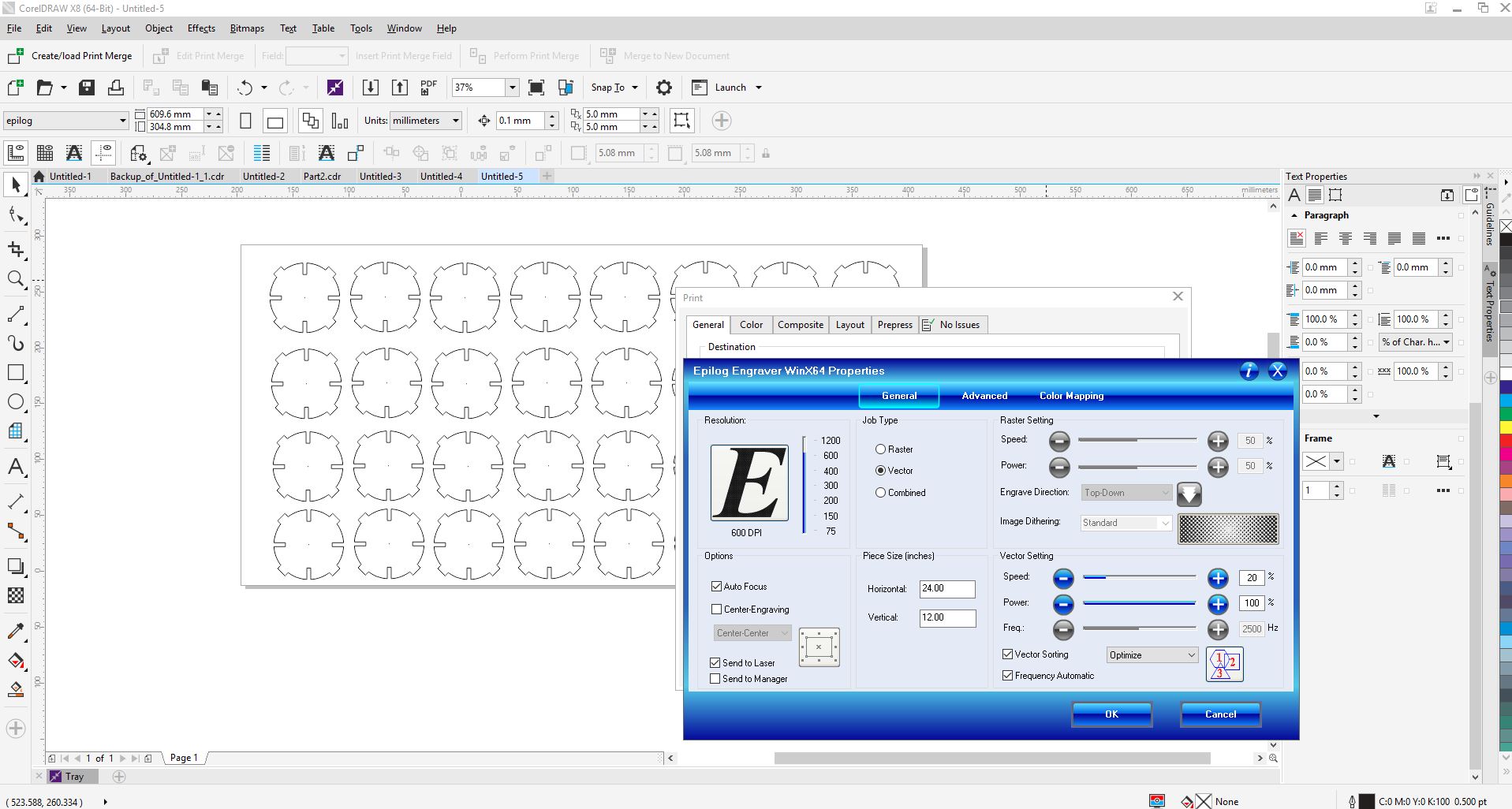
After designing this shape in Solidworks, I saved that as dwg, to import it in Coreldraw to be cut with the laser cutter. I input the correct the vector settings, with the power at 100% and the speed at 20% -- depending on the type of material I have been using these settings can change.
The laser cutting process
Laser cutting is a precise method of cutting a design from a given material using a CAD file to guide it.
Step #1. Preparing your artwork
Here, you need to prepare your work by setting right hairline thickness depending on what you are going to do either engraving or cutting.
The machine reads vector strokes of hairline thickness as thin as you make them.
Step #2. Configuring the laser cutter’s settings
You have to lay your chosen material in the machine bed and configure the machine to cut your artwork. You need to do some adjustment;
the Power, Speed and Frequency to suit your specific material. In FabLab the maximum sheet size we can cut is 600mmx 300mm.
Step #3. Process your job
The machine will then follow the path of your drawing strokes to cut out the components you have drawn.
Depending on the material, some of them usually have a protective backing during the laser cutting process that can be peeled away
after the cutting is complete. This protects the surface from heat and burn marks.
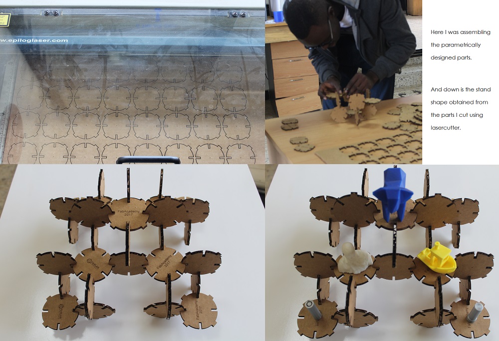
I just began to machine and assemble the parts. The stand was made successfully.
Download my parametric design files
Vinyl cutting
I was interested in printing FabLogo and attaching it to one of our tables. Here are the steps how I converted that photo into vectors for the vinyl cutter to read it and cut it out.
Vinyl Cutting Process
The vinyl cutter uses a small knife to precisely cut the outline of a picture into a sheet or piece of vinyl. The knife moves side to side and turns, while the vinyl is moved beneath the knife. What results from the cut process is an image cut into the material. The material is then 'weeded' where the excess parts of the picture are removed. It is possible to remove the positive parts, which would give a negative sticker, or you could weed the negative parts, giving a positive sticker. Removing the letters would be like removing the positive, giving a negative image of the word, etc.
Step 2:
Initially, you will need to create a sticker of a basic design.
Find or make an image that you want to make into a sticker. You can create an image with any 2D software. Other programs can work fine.
It is advisable to make you image black and white with no gray for best results.
Save the image as a JPEG The software running the cutter likes to have a jpeg, Scaleable Vector Graphic (.SVG) can work fine as well.
Step 2: Using the Software.
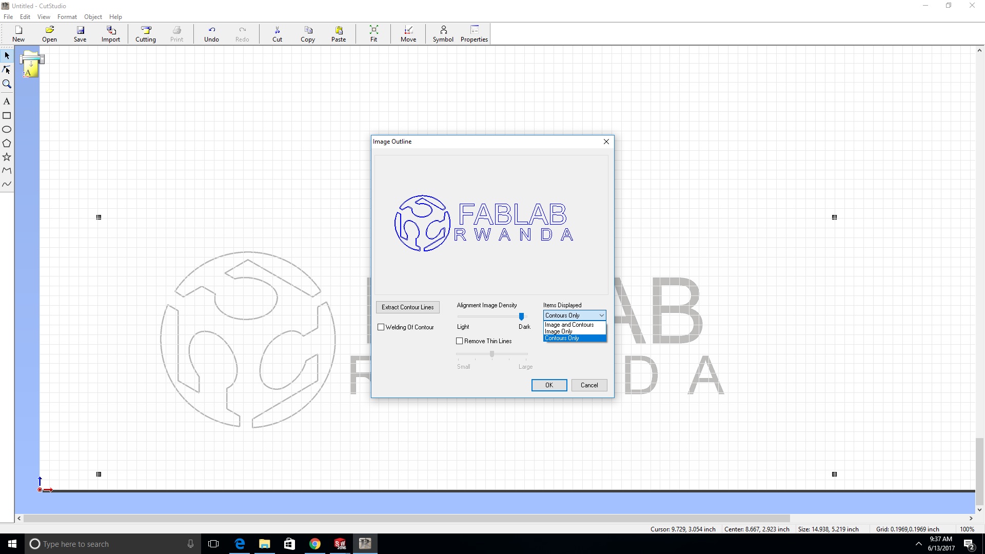
Open Cut Studio,
Import your image. It should show up as a grayed out picture.
Right click on the image, then choose Trace Image Outline
A dialog box will come up, you can adjust the accuracy of the cuts by adjusting the values.
You will see an outline of your image laid on top of the picture.
Click the Move button on the upper right to put the outline in the bottom right of the design area.
Next, delete the picture.
Right click on the picture and choose 'Properties'
There are three tabs. For size, set the size that will fit your sample piece of vinyl.
Step 3: Loading the Vinyl
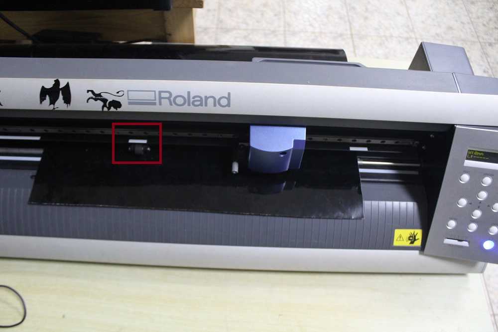
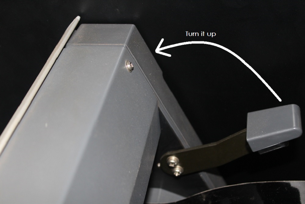
Load the sample piece of vinyl into the machine. On the left side in the front and back are two LED 'eyes'. These are infrared emitters and receivers which sense the presence of the vinyl. You have to position the vinyl so that it will cover these sensors. You also have to position the pressure rollers over the vinyl to make sure it will be able to handle the material. On the panel above the rollers, there are several white lines. The rollers must be positioned on these white lines or the machine won’t run. Make sure the vinyl is running straight, or it may slip out from under the rollers. Flip the pressure lever to make the rollers press down, holding the vinyl between the rollers and the pressure bar.
Step 4:
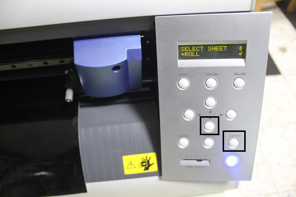
Check the display. It should say Sheet unloaded until you engage the pressure roller. Then you will need to use the down arrow to tell the machine
you have loaded a piece or a roll. If you choose piece, the cutter head will move sideways, measure the space between the rollers,
then it will move the piece out, the back in, then to its original position. This process used the 'eyes' to measure the height of the piece.
you then should be able to see the readout on the display of the pieces measurements.
Step 5: Cutting
Press the Cut button on the icon bar.
The cutter head should then move side to side and the vinyl should move back and forth.
When the design is cut, you can use the arrow keys to move the vinyl out of the machine.
There is a groove on the front of the machine. Use a razor knife in this groove to cut the piece off. If there is enough material left, you can leave it in the machine for the next person.
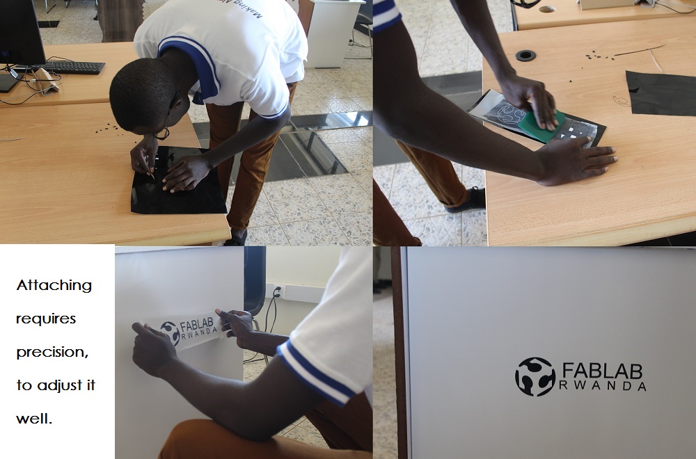
After modifying the FabLab Rwanda Logo, I used the above steps with vinyl cutter to cut the Logo.
I had to remove some parts that I will not need in my logo, and I covered the sticker with another one that will hold my logo while attaching it to the object. Below are the photos that shows the process how I did it.
Read more about vinyl cutting process