FabAcademy2017 - Projects
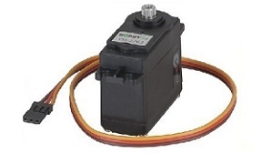
Output Devices
March 29, 2017 - Week#10
I did output devices together with the Input Devices all at the same board which is also the board I am using for my final project.
It was time to draw the board. I had to transfer my schematic diagram into a drawing of my printed circuit board. Drawing PCB’s is artwork. I took my time, and make sure it looks good. I followed the design guidelines for drawing my circuit boards. Most PCB software will have tools that will help you draw your board from the schematic. I can’t mention them all, but I’ve used Eagle to help me make my circuit.
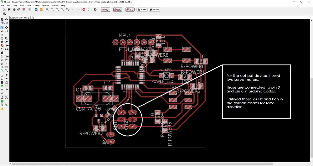
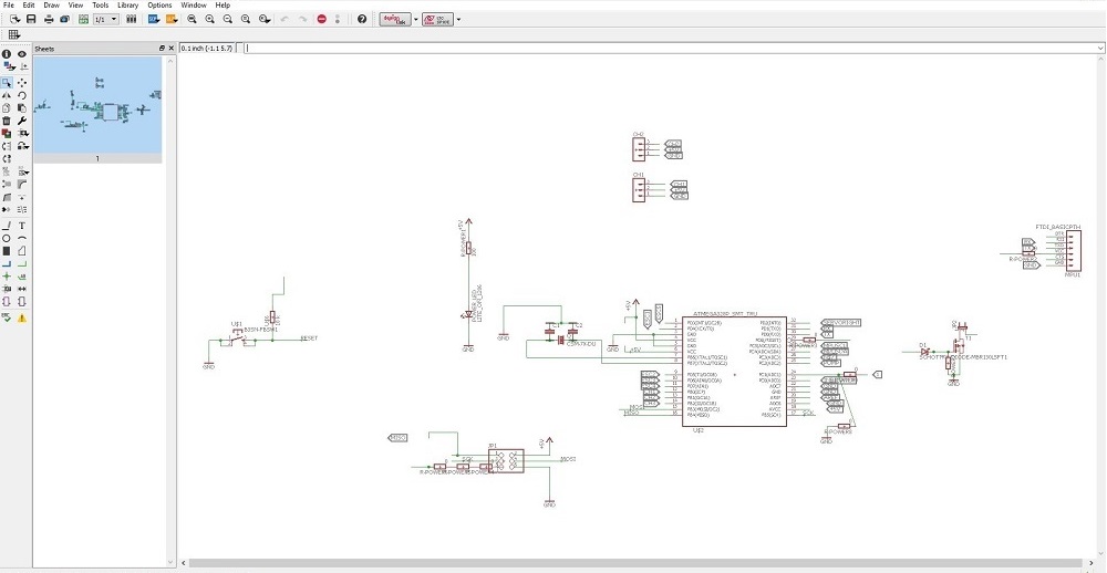
Before I start drawing wires and stuff, I needed to know what circuit I want to build. So I had to find or design schematics for my circuit. And I needed a PCB design software So, I used Eagle. Then I was ready to begin the process. I Started by drawing my schematic diagram into the software "Eagle".
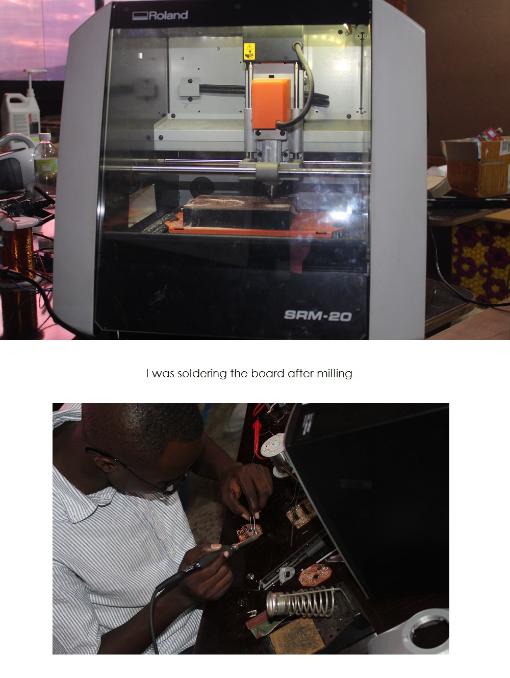
Printed circuit board milling (also known as: isolation milling) is the process of removing areas of copper from a sheet of printed circuit board material to recreate the pads, signal traces and structures according to patterns from a digital circuit board plan known as a layout file.
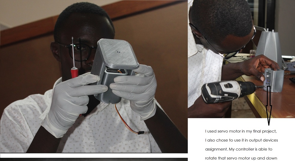
I just designed the body for the motors to be attached on my Robot. below you can see photos. It is important to do design for everything before making. I enjoyed assembling different parts of my Robot, especially the side of motors was amazing when seeing my tilt and pan movements working smoothly.
Here the codes I wrote to run my motors, the command is from raspberry pi to the chip I have made and then run motors:
/*Codes for servo motors.*/
#includechar tiltChanel=0; char panChanel = 1; #define pinTilt 8 #define pinPan 9 Servo servoTilt, servoPan; char serialChar = 0; void setup() { servoTilt.attach(pinTilt); servoPan.attach(pinPan); servoTilt.write(90); servoPan.write(90); Serial.begin(57600); } void loop() { // put your main code here, to run repeatedly: while(Serial.available() <= 0); serialChar = Serial.read(); if(serialChar == tiltChanel){ while(Serial.available() <=0); servoTilt.write(Serial.read()); } else if(serialChar == panChanel){ while(Serial.available() <= 0); servoPan.write(Serial.read()); } }
After writing codes to control my motors, everything was fine, my motors were ready to rotate in both directions.
Below is a video that shows how my servo motors react!