Week 13 - Input devices
This week we will do input devices. This means we design a circuit board that has a microprosessor and one or more sensor from which we read data into ADC port on microprosessor. It could be light, sound, movement, magnetic fields or many others you can come up with. I desided to use a hall sensor that measures changing magnetic field. This will help me on my final project as I am planning to use hall sensors as closed loop monitoring of the motion/position of the pcb moving in the through hole plating machine. See the final project page here.
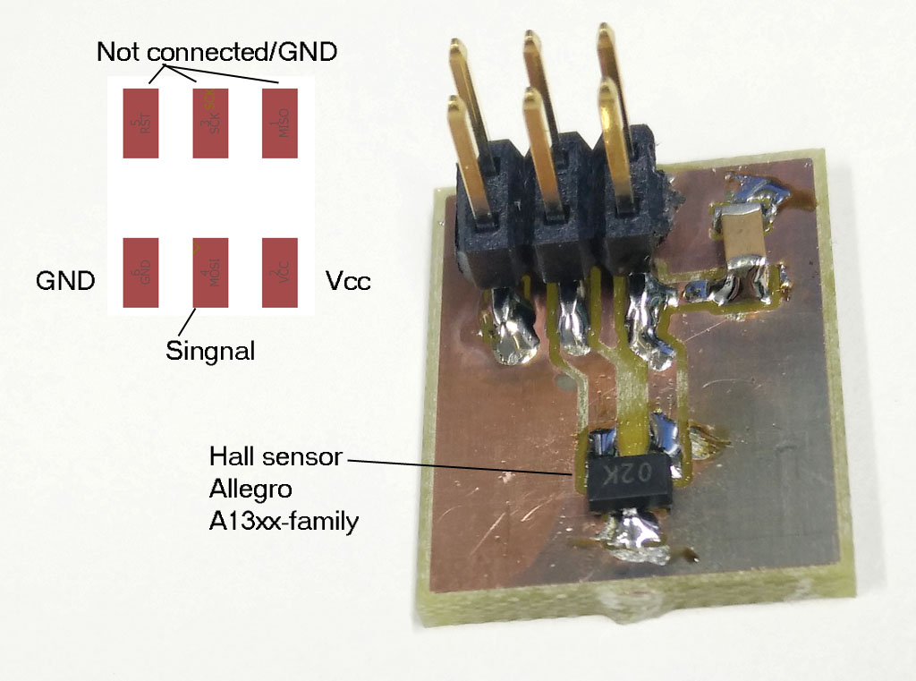
Hall sensor
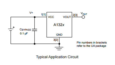
Fab Lab stock has one hall sensor. It is Allegro MicroSystems manufactured SOT23W-packaged analog sensor and has single axis magnetic field sensing capasity. Here is a link to Digikey page of the sensor. The typical schematic diagram for the chip is quite simple so it will be easy to integrate to a board.
The board for the hall sensor
For this weeks assingment to help me finish my final project, I realized that I have to use ATMega328P-microprosessor with this sensor. It is quite an overkill chip for just to read the sensor information but for my final project I had desided to use my own build version of Arduino UNO. So to manage this week and put forward my final project I desided to use this microprosessor.
Luckily we had ATMega328 microprosessor in Fab Lab stock as well. So again I navigated to digikey www-page to find more information of it. Datasheet is here. This is quite a capable microprosessor compared to the earlier ATtiny44 and ATtiny45 prosessor that we have used on earlier weeks assingments. ATMega328 has a lot more of memory for programs and for data and it has more I/O-pins for use. For comparison ATMega328 has 32KB of program memory compared to 4KB on ATtiny44. Mega has 32 pins compared to tinys 14 which means a lot more I/O and capabilities.
Here is the pinout of the microchip.
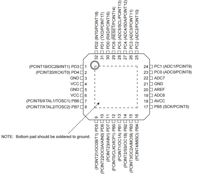
To put it clear, it would be more than enought to meet my needs for the final project.
Blan B
Later in the week i realized that I do not have time to make my own Arduino board for this week. So i jumped to plan B. On week 8 as extra work I had designed a board with ATtiny44 which had I/O pins connected to header pins for adding something to the board after. I never finished it completely but it was almost done. I desided to use that and make a sort of breakout board for my hall sensor to be connected to my earlier board. This would work well with my final project as well, as I have to put those hall sensor around the through hole plating machine, so they can not be on the main board anyway.
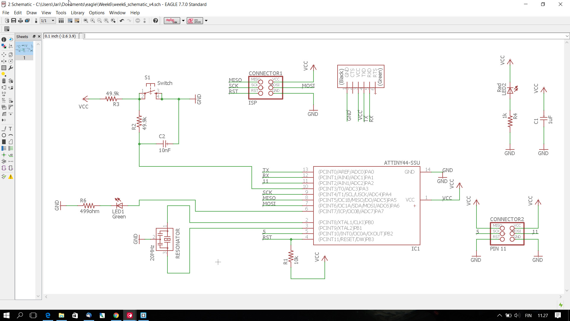
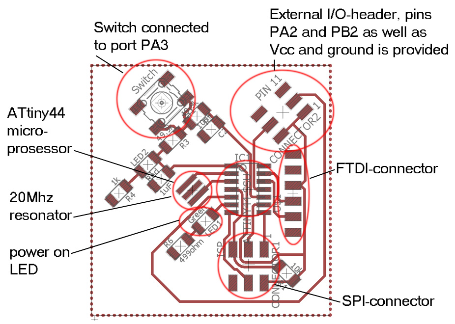
This is what the board looks like from Eagle PCB design program. It has ATtiny44 microprosessor, 20Mhz resonator, ISP-programming interface connector and one 6 pin header that provides board voltage (5 V in this case) and ground to the connector and two microprosessor I/O pins, PA2 and PB2. This means that I could connect two external board to this board and I could provide them with power and interface them with I/O-pin. From these PA2 can be used as ADC-input among other things. Port PB2 unfortunately can not funtion as ADC-input, but as I only need one ADC-input for this week the board will work fine. As was earlier needed this board has also a button and a FTDI-connector.
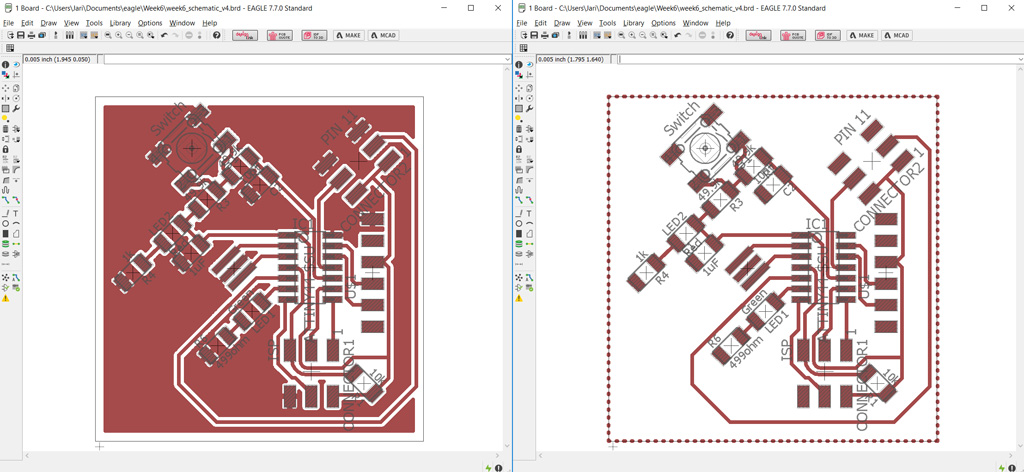
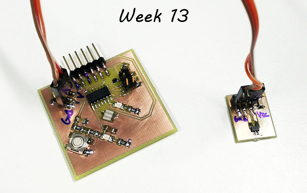
Overview of the board.
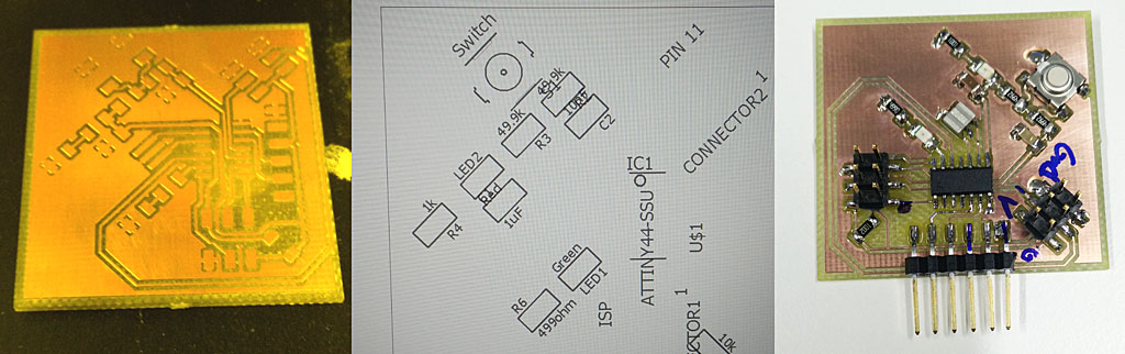
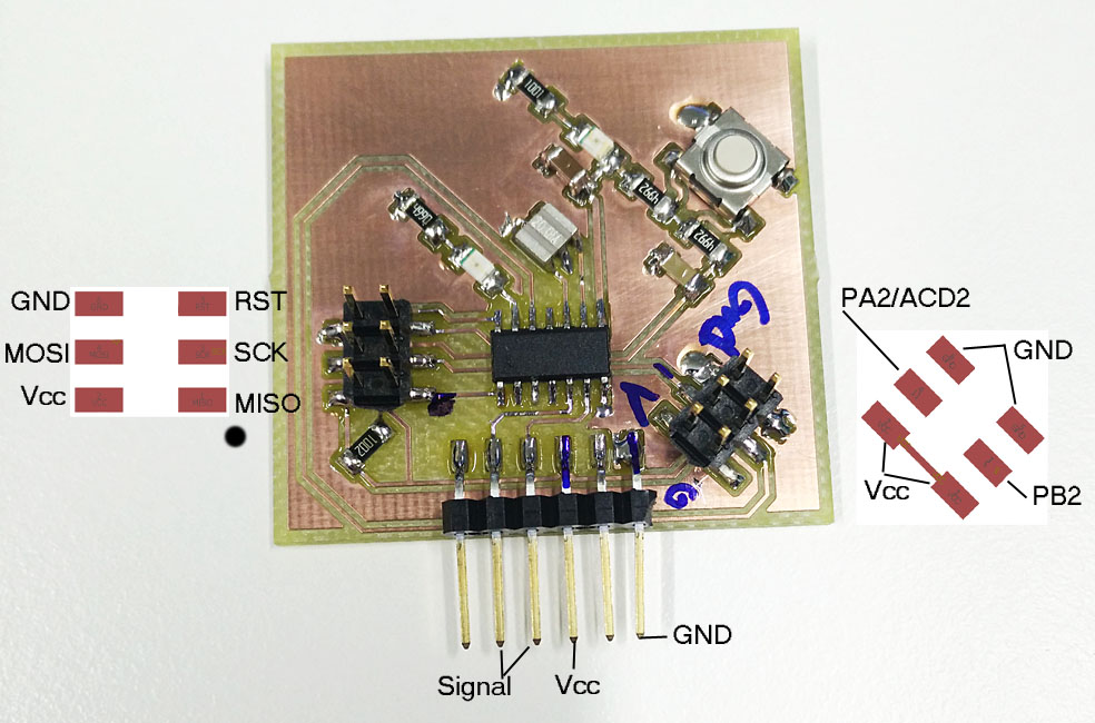
I had milled a board already on that week but did not have time to put the components on. Now I collected the components and soldered the board. Here is the result.
Connections on the main board.
Hall sensor Breakout Board
Next step was to desing the hall sensor breakout board.
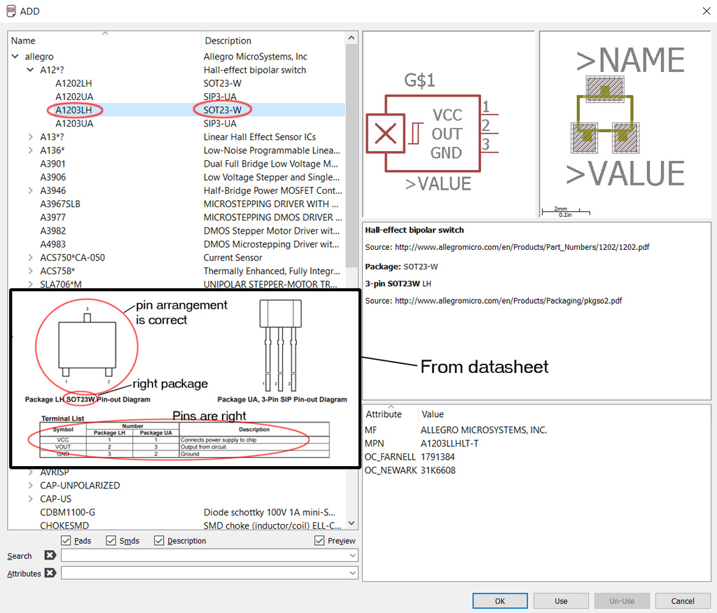
Using fablab Eagle library, I could get some components but for example hall sensor was not available. Luckily Eagle comes with quite a library on its own so I found the right component from Allegro-library. Here is a picture from Eagle Add component from library window and a piece of hall sensor datasheet.
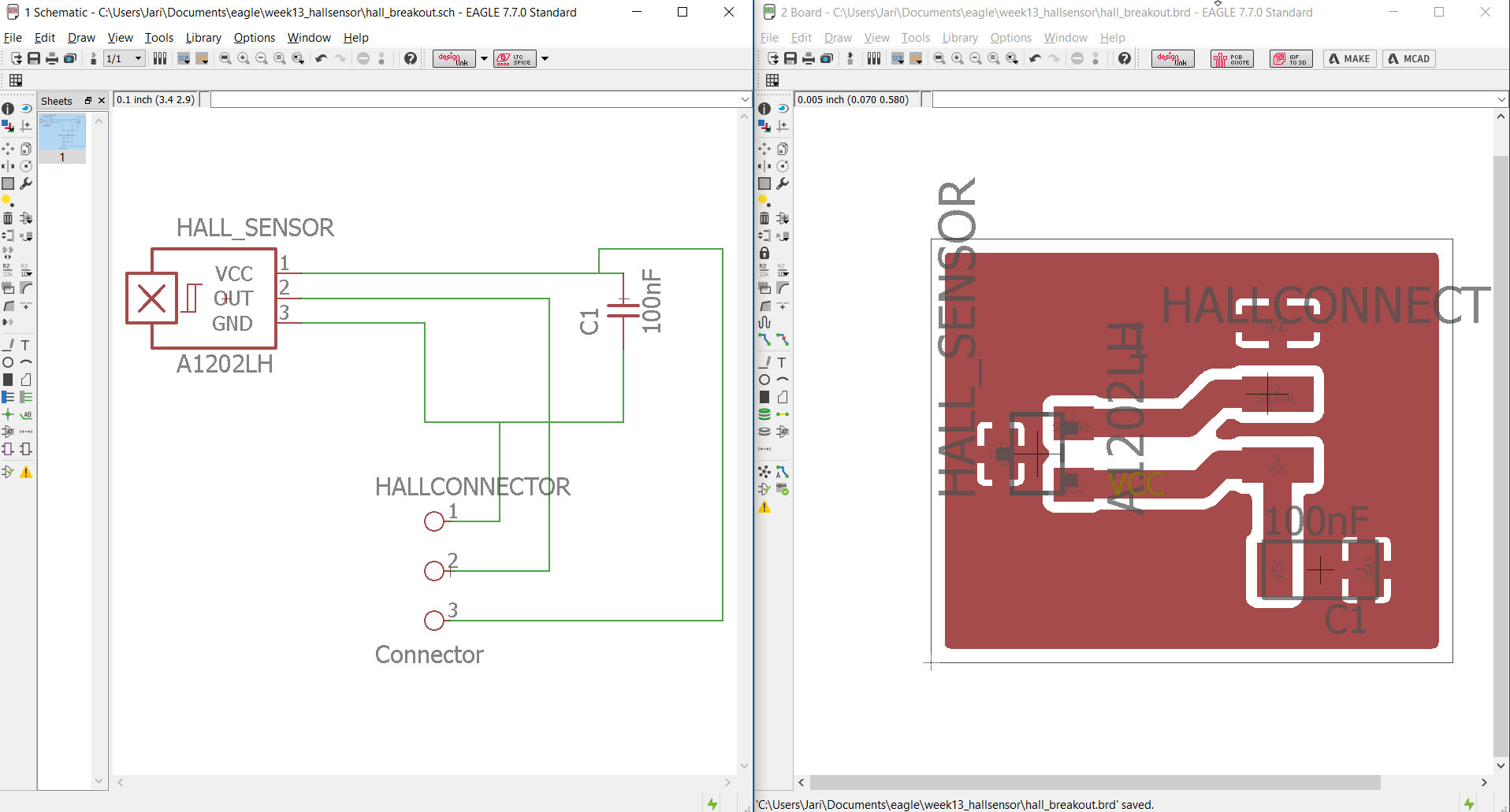
I used Eagle to desing Hall sensor breakout board. Here is the result. It is extremely simple board with hall sensor and capasitor and a connector to connect it to my main board. Eagle designing is explained on week 6.
Now that the board is designed, I have to export an .png image for the fab modules process to get the milling prosesses calculated. I could also export this board as Gerber file and mill it on my own milling process but I desided to do this one with the fab lab process.
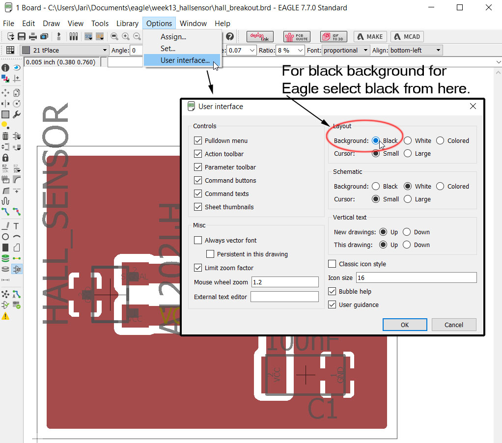
I made some errors to start with, I had white background and it had to be changed to black and I exported all the layers. To change the background to black on Eagle go to Options -> User Interface and change the Layout background to black.
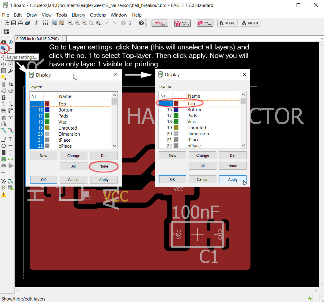
Now background is black, I must de-select all the layers but the top that I want to export. To do this, go to Layer setting, unselect all layers from "None" button, select Top layer or the layer you want to print and click apply. Now you have only the layer or layers that you want visible.
Then it is time to export the .png file. Go to File -> Export -> Image. Select the location and name for the file on "File" part. Select Monochrome tab to make picture black and white and define resolution to 1500 dpi as minimum. Then click OK. Notice that on my picture I still have white background and all the layers selected. Dont let that bother you.


Modifying the process in Gimp to get the traces and outline .png images is documented on week 6. I used the same procedure to make the files for milling. Milling the board is documented on week 4.
Here is the final breakout board after milling and putting the components on the board.
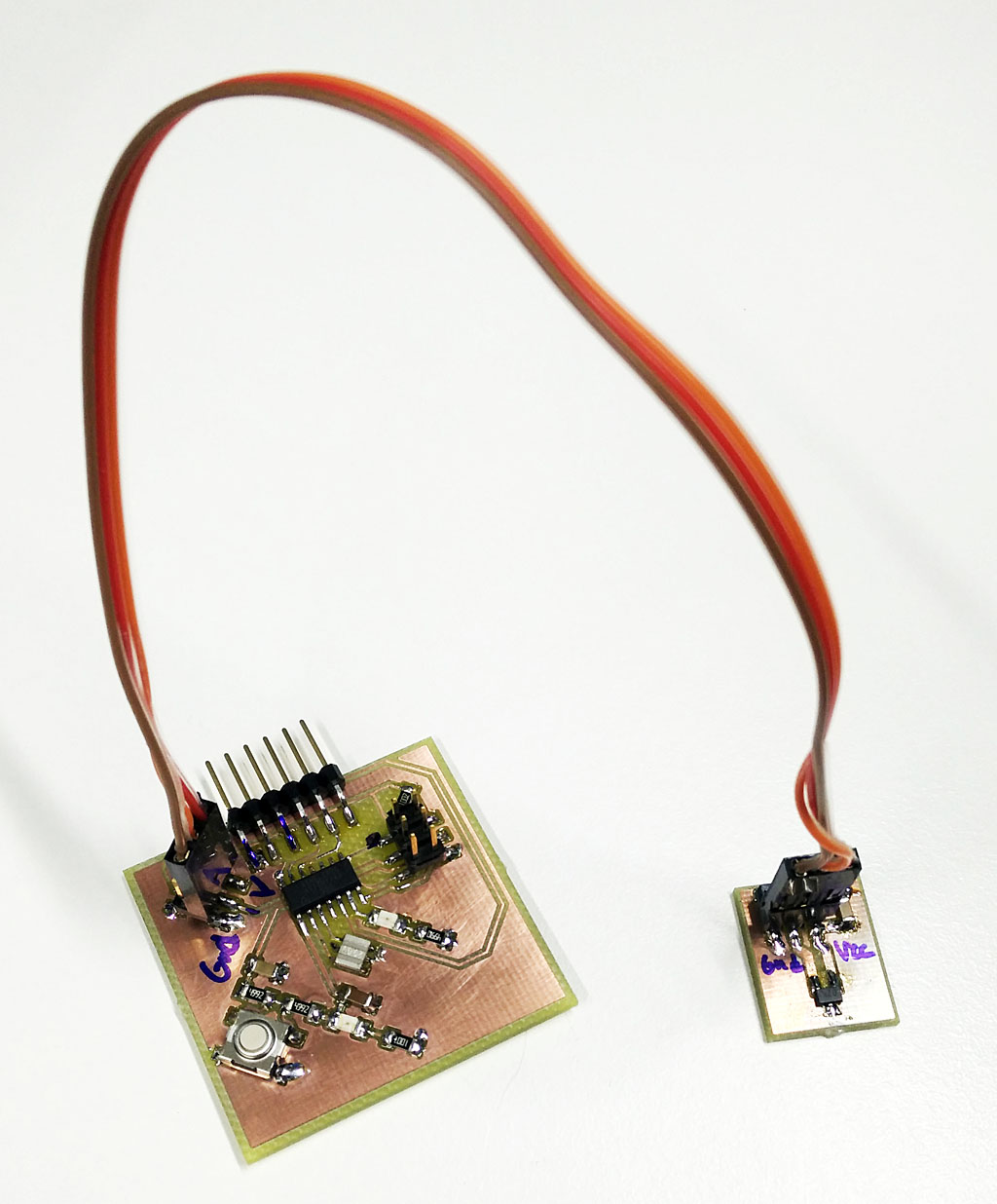
Setup
Finally I have the whole setup ready.
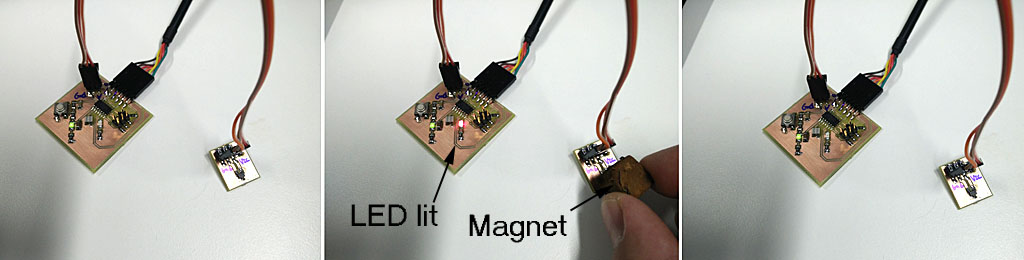
Now it is time to program the board. I used a code for ADC usage at www-page giving examples of using ADC on attiny85. The page is called Marcelpost.com. I modified the code for use on my board. In all it's simplicity I am reading the ADC value and when magnet is brought next to the sensor a red led will light on the board.
On the code I included delay.h for delay function, defined the ports that the ADC is going in and the pin that the LED is connected. I also modified what happens when certain ADC values are reached. On my code the led is simply lit when ADC voltage is more than half of reference voltage that in this case is Vcc. Most of the code is to intialize and use of the ADC which is directly used as it is.

Here are some pictures when testing the board with a magnet. The red led will light up when magnet is next to hall sensor. On my final project this will verify that the pcb has moved to right position to be lovered into one of the tanks. There will be a magnet or a sensor on all the tanks.
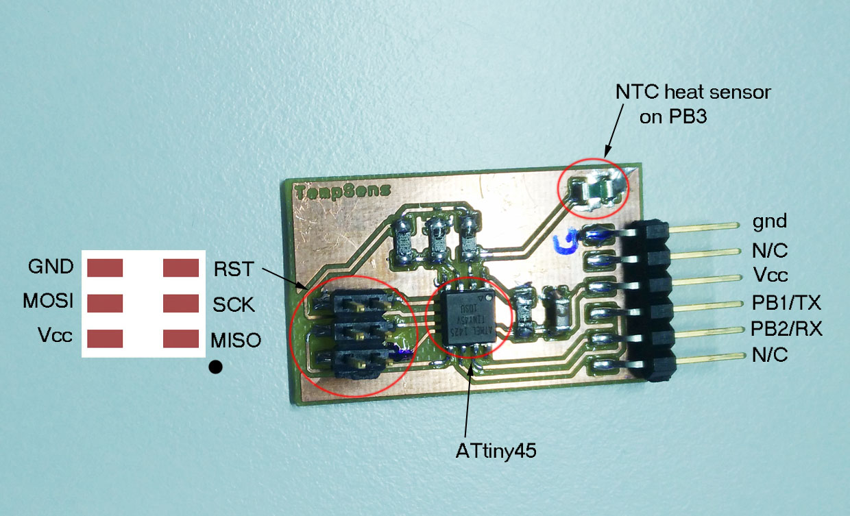
Week 16 temperature sensor debugging
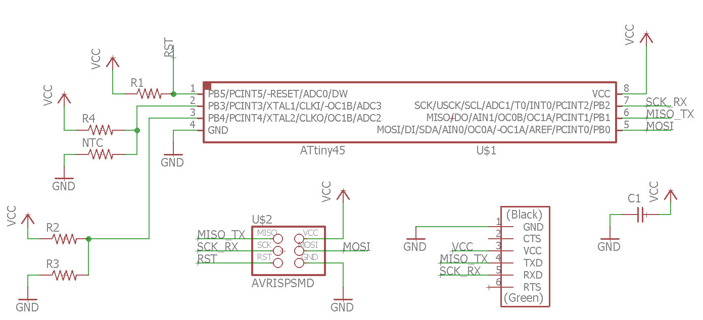
On week 16 - application programming I did temperature sensor. It is one of input weeks example boards:temperature sensor.
I had some issues with the board and had to do some debugging on it. I moved the documentation of that process here as it fits here better.
Trying to figure out what was wrong with my sensor board or the serial communication or application code example we got from Jani. I did the following procedures. It was a lot of shooting in the dark as I did not have clear picture from where to start searching problem/problems I had.
I did many different debugging procedures to see if things were as supposed. Here I list the tasks I did trying to figure it out. These are useful on any electronics debugging situation and can be used on many Fab Academy weekly assignments.
Here is the board on hand.
Board schematic
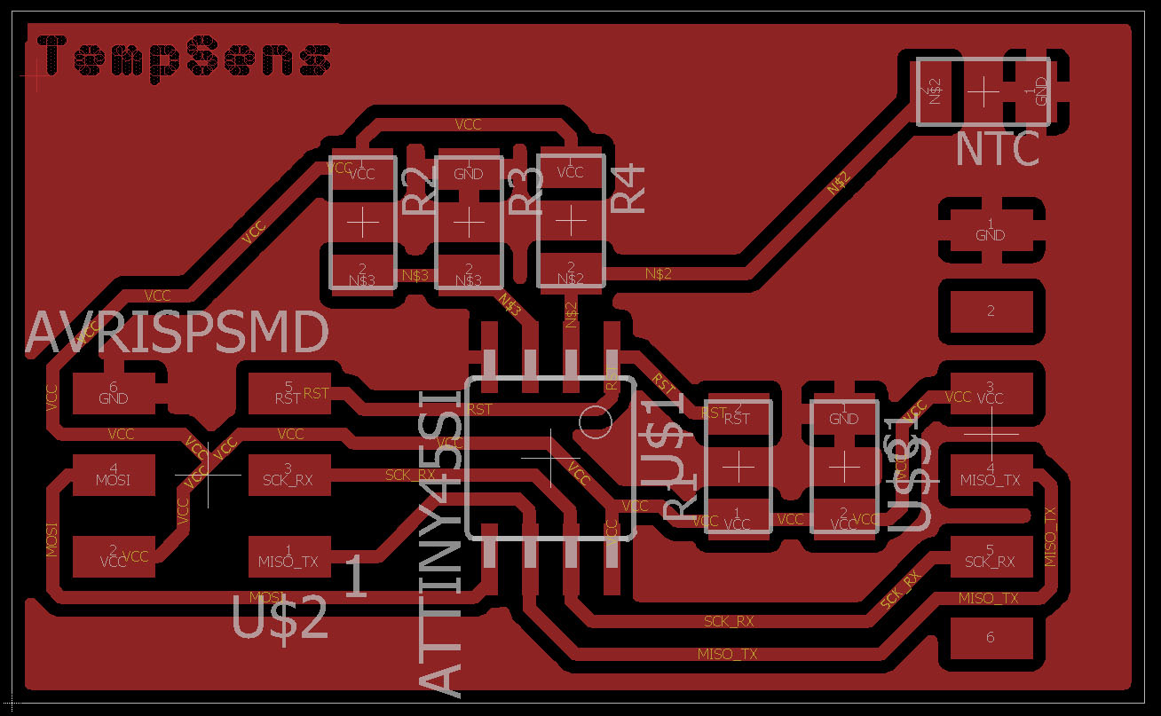
Board BRD file
Reading the fuses on ATtiny45
On my Avrdude 5.11 to read fuses from microprosessor. On the console write:
Avrdude.exe -c usbtiny -p attiny45 -U lfuse:r:-:i This will give you the fuse bits.
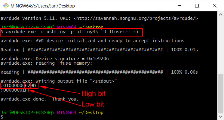
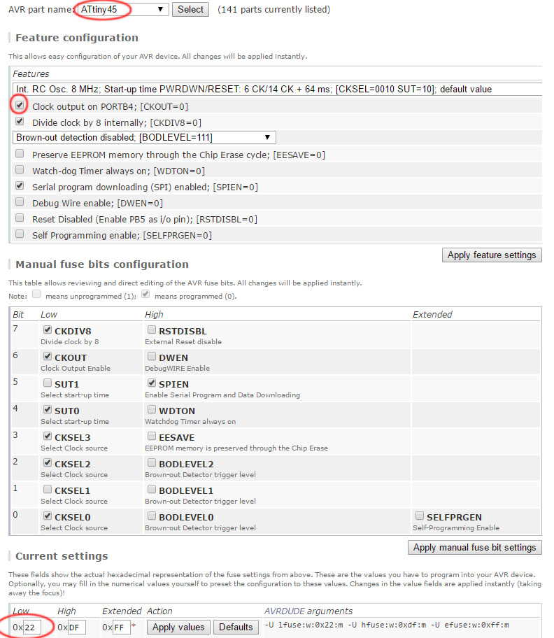
Looking from Engbedded.com shows that low fuse 0x62 is default setting with internal 8MHz clock with divider value 8. This is what is should be. On this setting it would run on 1MHz but on Neils code the divider bit is re-written to be off so the microprosessor works on 8MHz.
Correcting the code with prosessor speed definition
On Neils code, he does not define clock speed for the compiler (?). This will give error message when compiling the code with Atmel AVRStudio but it will still generate the hex-file.
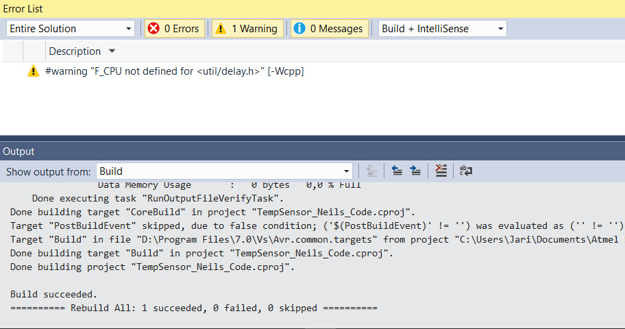
This is corrected by adding definition to the code. This definition must be added to the c-code before #include util/delay.h
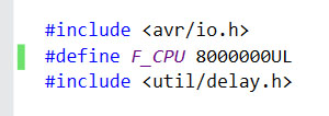
Now there is no warnings on the build.
Measuring the actual prosessor clock speed with oscilloscope
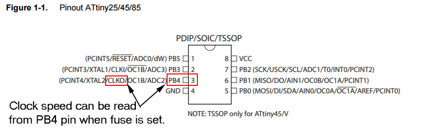
To read clock from microprosessor fuse bit must be written so that there will be clock signal on pin PB4 on our ATtiny45 microprosessor. Again from Engbedded.com right fuse setting is to change low fuse bit to 0x22.
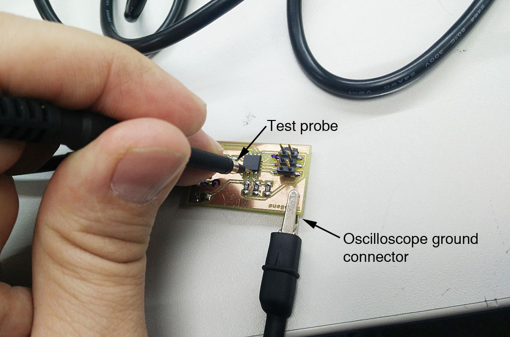
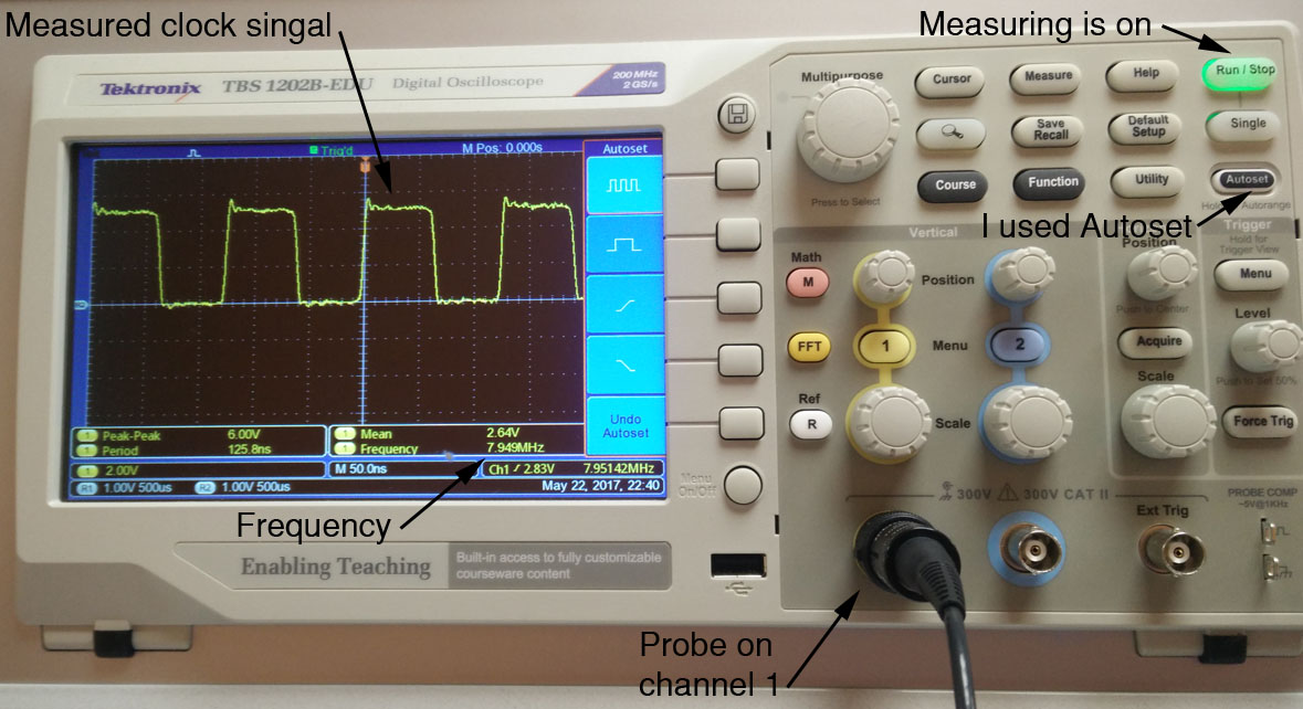
After setting the fuse I read the pin PB4 on microprosessor with oscilloscope. On oscilloscope I am using channel one and Autoset. I connect the ground of the probe to ground on my board and probe to PB4. This gives nice clock signal on the scope.
When measuring prosessor clock speed from PB4, I used oscilloscope channel one. I attached the ground connector of the probe to pcb ground and measuring head to correct pin.
On the oscilloscope, using autoset function the scope will automatically scale the read singal to the screen. From there I can see that the clock speed is about 8 megaherst as it should be.
Calculating bit_delay value for the actual clock speed
Measuring voltage change on ADC-input pin with multimeter
Checking if there is activity on serial output port on ATtiny45
Editing the example code to show out received values
Files used with this weeks assignment
Eagle files schematic
Eagle files board
Gerber top-file
Gerber outline-file
Top .png-file
outline .png-file
FabMods top mill file (.rml)
FabMods outline mill file (.rml)
program .hex file
program .c file