Serial Asynchronous
This week I was building a network among 3 processors: one ATTiny45 (bridge aka node 0) and two ATTiny44 (nodes 1 and 2). Based on Neil's design of the bridge board, I created a schematic and a board layout for my bridge board. For nodes, I used boards made during week 6 and week 13.
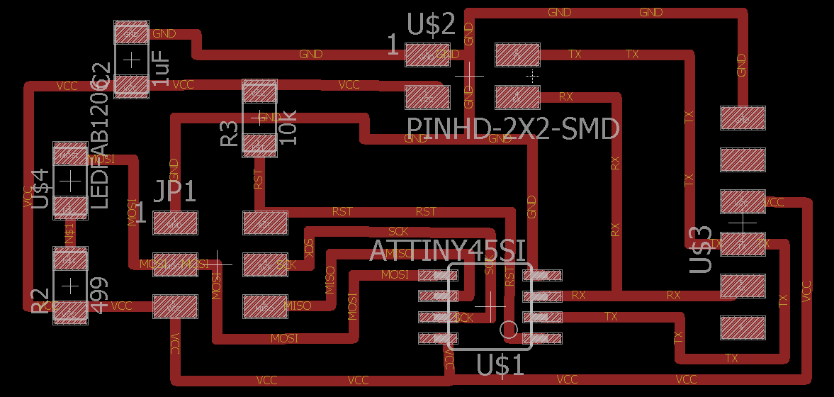
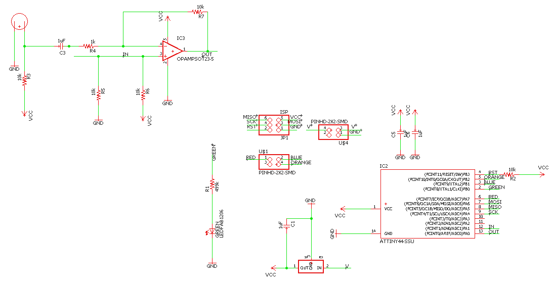
Bridge Layout
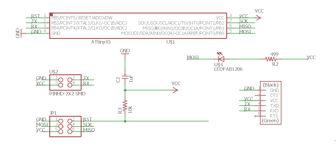
Bridge Schematic Node (week 6) Layout
Node (week 6) Schematic
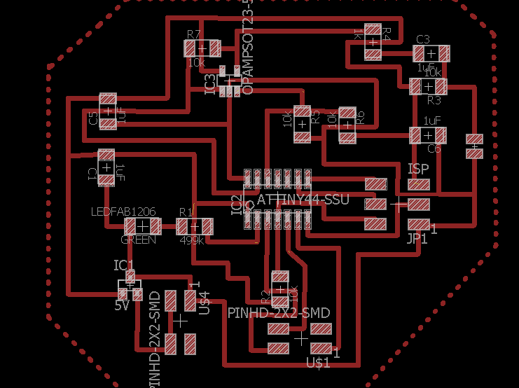
Node (week 13) Layout
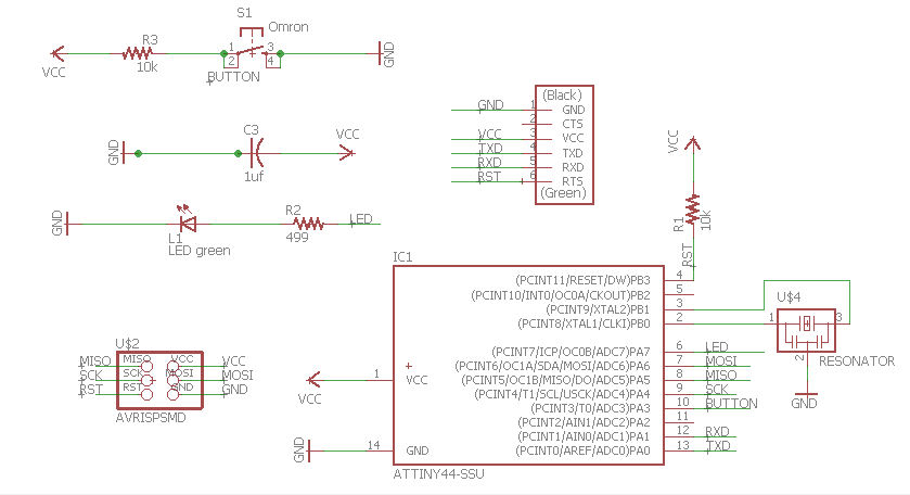
Node (week 13) Schematic
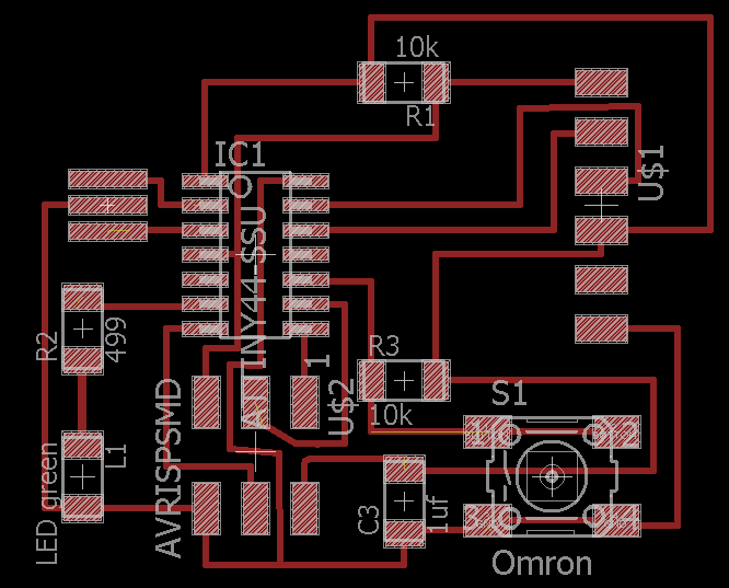
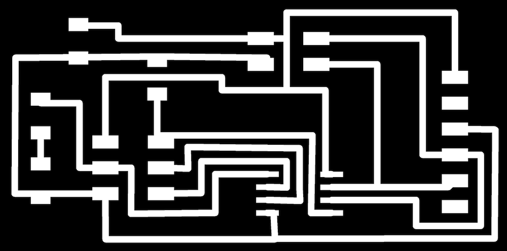
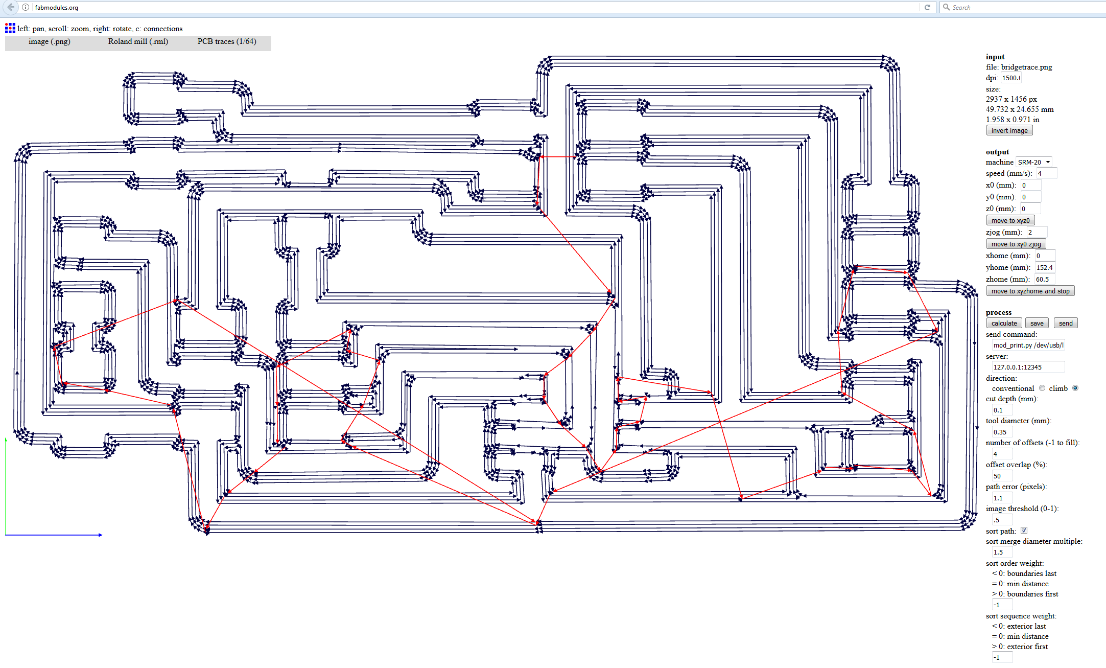
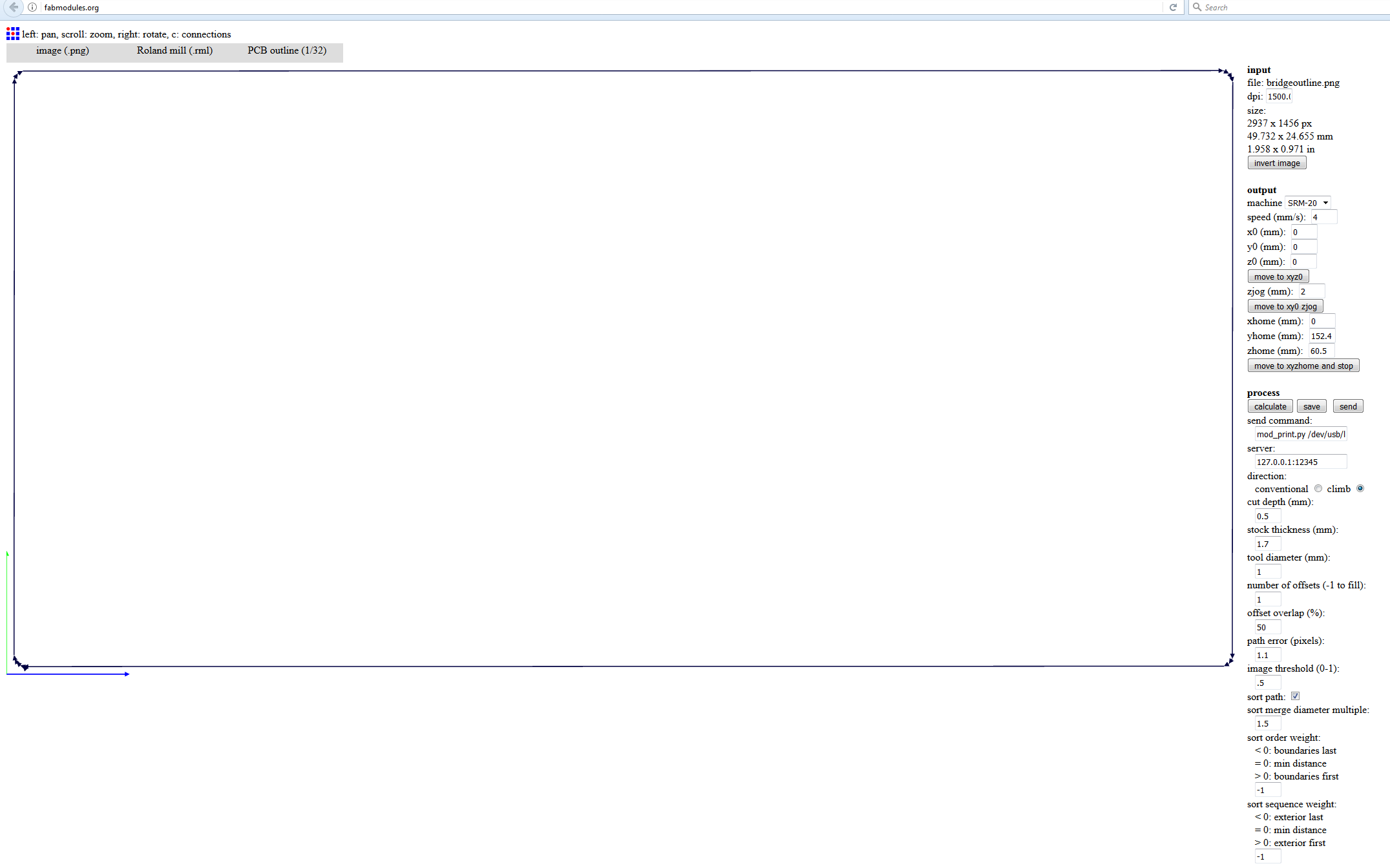
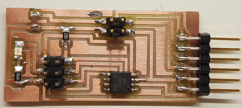
I created traces and an outline for the bridge board, milled and stuffed it
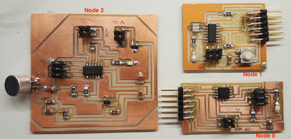
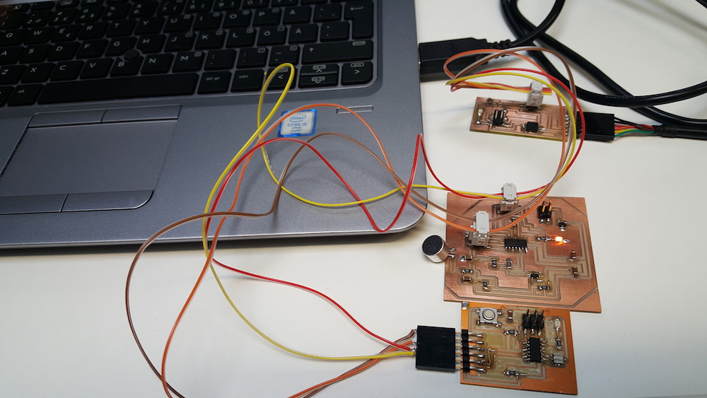
Three boards to be used in the networking
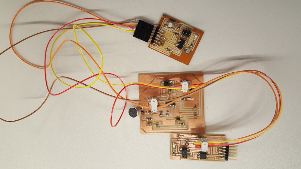
Connecting the boards
Initially, I tried to figure out how to program use SoftwareSerial library to program the boards in Arduino IDE. However the library was not working for the Tinys, and I was not able to find the right one.
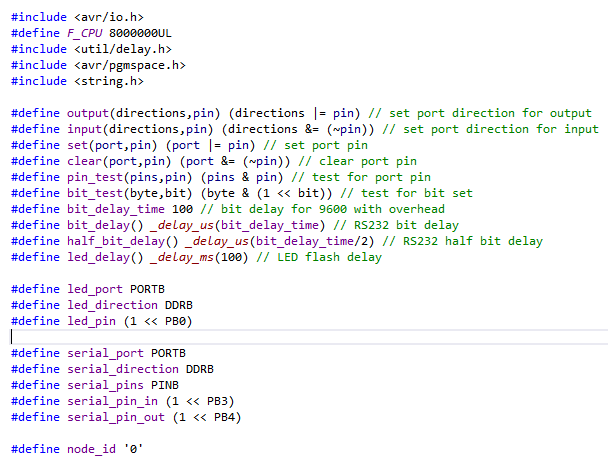
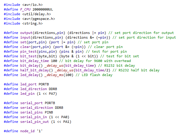
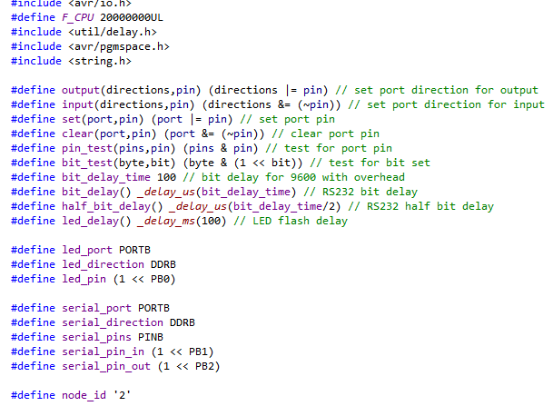
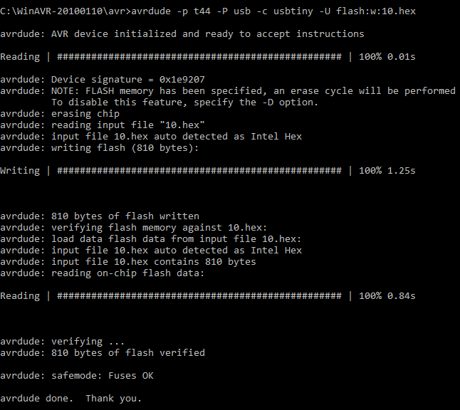
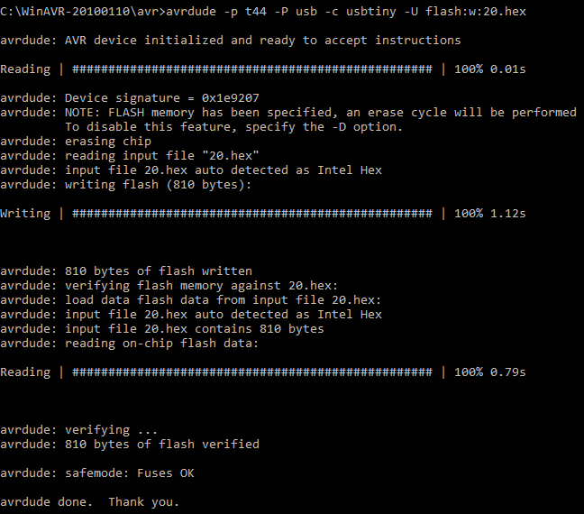
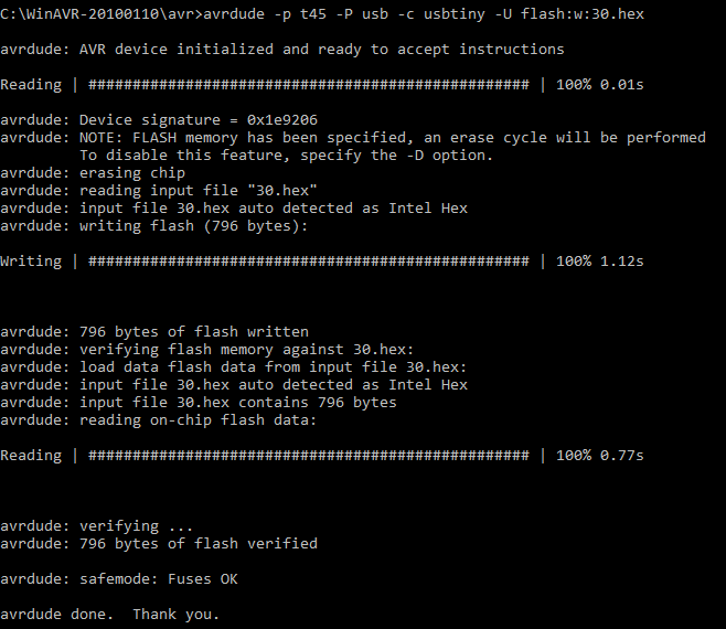
So I continued programming with Atmel Studio. To get started I used hello.bus.45.c code. I modified the code for all Tinys (added the F_CPU definition and changed pin numbers to match the pins of my boards), compiled the code and created .hex files for programming microcontrollers with avrdure.
- ATTiny45 (bridge aka node 0)
- ATTiny44 (node 1)
- ATTiny44 (node 2)
Avrdude programming seemed to have gone fine.
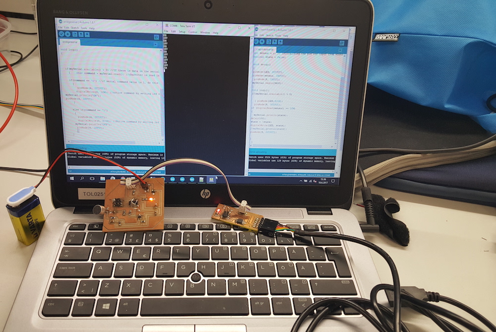
However, when I started testing how networking functions (using Tera Terminal), I did not get the desired results. The only thing happening was blinking lights on the bridge and node 1, when any key on the keyboard is pressed. Node 1 showed no signs of live, and no text is appearing in the terminal. The result was the same in PuTTy terminal.
I tried removing F_CPU definitions I added to the code, but that did not help. So still need to figure out how to fix these issues.
Later, our FabLab manager Jani helped me finding errors which prevented getting the required result.
The issue with the bridge was the internal frequency of the microprocessor. Instead of the 8 MHz, it was functioning with about 8.68MHZ, so the delay bit_delay_time had to be readjusted to get it functioning with this frequency. I set it to 108 (8.68 / 8 = 108.5) The the second node had incorrectly defined F_CPU, which was 20000000MHz instead of 8000000MHz. After I this was fixed the network of the two nodes was establilshed.
Due to the absence of time, I decided to use only two nodes and move on with the next weeks assignment as well as with the final project.
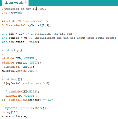
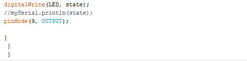
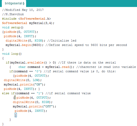
Later, I also decided to practice establishing networking for the same two boards with Arduino IDE. I modified the code I used for the sound sensor in the assignment of week 13 to include serial connection and I wrote a code for the bridge board.
To establish using the serial connection in Arduino, using SoftwareSerial.h library is required. I set up the connection between the two nodes in such a way that when the sound sensor's digitalRead changes, thus changing the state variable I used in my code, the state (either 0 or 1) is being print out in the terminal (mySerial.println(state)) and it triggers switching the LED lights on both boards on or off. Additionally, the bridge board (node 0) transmits the "ON" or "OFF" message to the terminal when its LED switches on or off.
Files:
Node 0 .sch schematic, .brd layout Eagle files, .rml traces and outlines files, node 0 and node 2 .c and .hex files, node 0 and node 2 .ino Arduino files