Redrawing the Echo Hello-World Board
After a comprehensive review of principles of electronics design in Eagle with the local Fab Lab expert Dorina, I installed and used the software on my laptop.
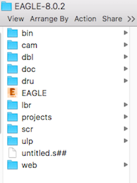
To complete this week's assignment, I used tutorials provided by Dorina and FabAcademy. I started with downloading and insalling component libraries. Library fab.lbr is located in the Electronics design Fab Academy page. It has to be saved in the Eagle local folder (e.g. on Windows C:\EAGLE-7.5.0\lbr or on Mac /Applications/EAGLE-7.5.0/lbr).
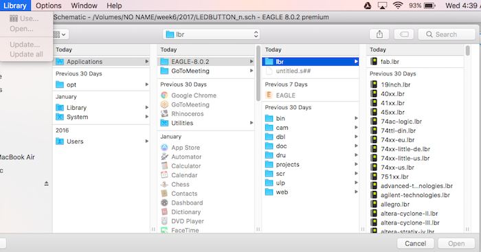
This library contains all the components needed to design and produce the board. To install the library in Eagle, go to the top toolbar and select the Library menu then select Use.
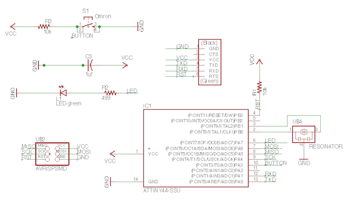
After that, I redraw the echo hello-world schematic. To work with the Eagle interface, I used Graphical Icons Toolbar. Here are the components used and libraries where they are located.
| Component | Name | Library |
|---|---|---|
| 6-pin programming header | PINHD-2X3-SMD | fab |
| attiny44A microcontroller | ATTINY44-SSU | fab |
| FTDI header | FTDI-SMD-HEADER | fab |
| 20MHz resonator | RESONATOR | fab |
| capacitor | CAP-US | fab |
| pull-up resistor (10k) | RES-US | fab |
| ground | GND | supply1 |
| VCC | VCC | supply1 |
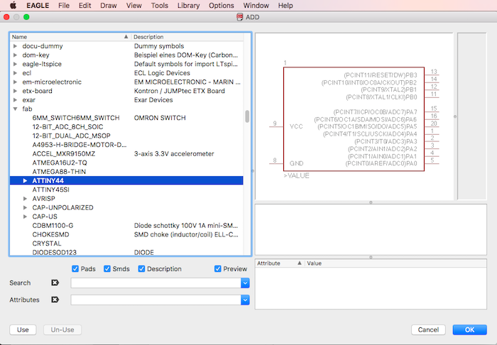
To add components: Add button on the Toolbar - fab OR supply1 - choose a component - OK
After that, components need to be connected. In order to avoid net crossovers, I used an option to connect componens by giving the connecting nets identical names.
In schematic, I also used buttons
Adding a button and LED with current-limiting resistor
The next step is adding
| Component | Name | Library |
|---|---|---|
| button (OMERON switch) | 6MM_SWITCH6MM_SWITCH | fab |
| green LED | LEDFAB1206 | fab |
| current-limiting resistor (499 ohms) | RES-US | fab |
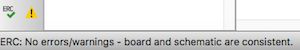
I used ERC, the electronic rules check in schematic view to ensure that the board will work.
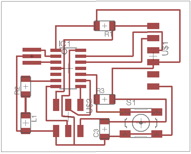
Then I switched to the Board Layout to route traces on the board.
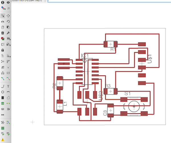
To finalize layout in the board view, I used buttons
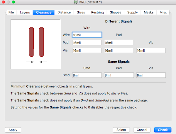
Checking the design rules, making and testing
I used DRC, the design rules check in board view to ensure my layout is error-free. Initially, I had
To fix the errors, I
I ended up with the following schematic and board view layouts
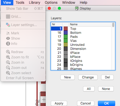
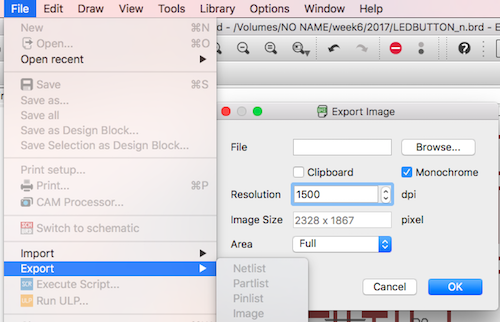
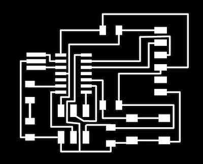
Next, I exported the top layer design from Eagle to monochrome 1500 dpi .png
As recommendered by local insttuctors, I used Gimp and to create traces and cutout for milling. I followed Dorina's instructions:
- Open the image in Gimp and create a new layer with foreground color black.
- Set Layer Boundary Size for the outline layer by adding 1.6 mm to width and height centered. This is the margin milled away by the machine with the 1/32 bit (2.54 inch/32 = 0.8 mm).
- Change the order of the layers in the Layers tab: on top the traces layer, and below the outline layer.
- Enlarge the image to fit all layers: Image - Fit canvas to layers. Then fill the empty area with black.
- To create the traces image file, export the image as .png.
- To create the cutout image file, fill the traces layer with white and export the obtained image as .png.
- These two files (traces.png and cutout.png) will be used in Fab modules (fabmodules.org) to create the .rml files used by the milling machine Roland SRM-20.
I generated the following files.

Next, following the same instrucions, I created the milling files (cutout test, traces and cutout) in Fabmodules for the Roland SRM-20 machine. The steps were the following:
- At http://fabmodules.org, select input format - image (.png)
- Select the file to process (e.g. traces.png or cutout.png)
- Select as output format Roland mill (.rml)
- For creating the traces .rml file:
- Select as process PCB traces (1/64).
- In the right-hand column change the parameters: x,y,z = 0
- The other parameters remain with the default values
- Calculate to obtain the milling paths
- Save to save the .rml file
- For creating the cutout .rml file:
- Select as process PCB outline (1/32)
- In the right-hand column change the parameters: x,y,z = 0
- The other parameters remain with the default values
- Calculate to obtain the milling paths
- Save to save the .rml file.
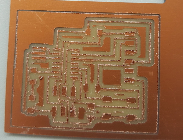
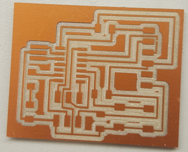
I had to do milling twice, since the first attempt failed.
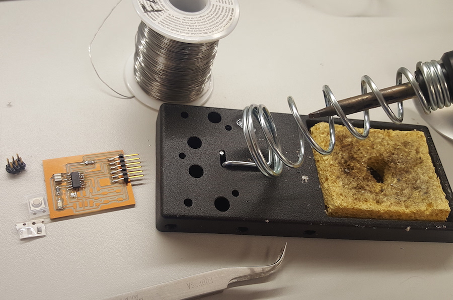
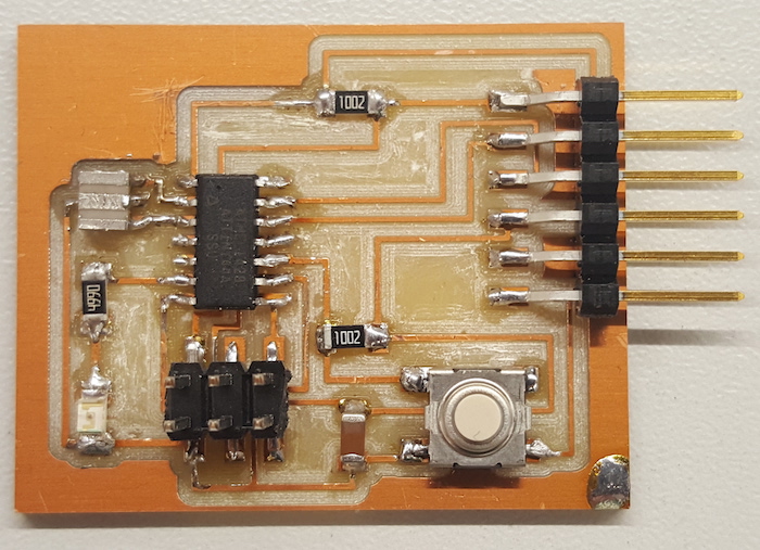
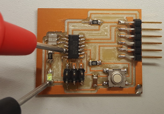
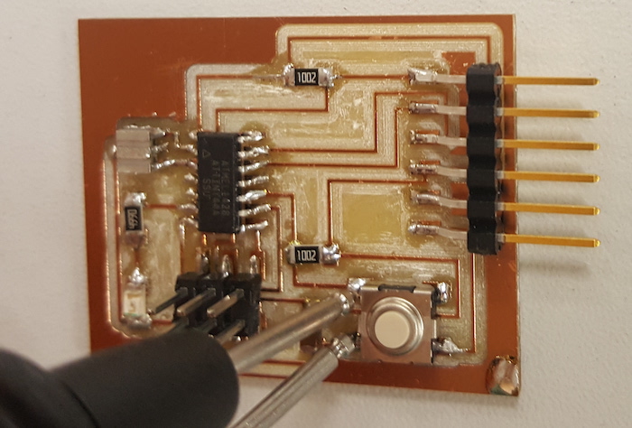
Next, components are collected and soldering started...
Files:
Echo hello-world with LED and button .sch and .brd files; cutout and traces .png files; cutout test, cutout and tracel .rml files
Remember, remember...
- Working in Eagle, don't close layout and not schematic (or vice versa) - you need to keep both open all the time! Closing one view while the other view is open (and making edits) will break the link between the two
- Check and correct errors found ERC and DRC in Eagle
- Find a right resistor for the light
- Make sure components are in the right direction before you start solding