The of the week was to create a board that can be used in the final project (or a similar board), a shower timer. I need a sound sensor to detect when water starts flowing. I decided to make a 9V battery-powered board which uses ATTiny44 with a LED light that would switch on when the sound is detected by a MEMS Analog microphone.
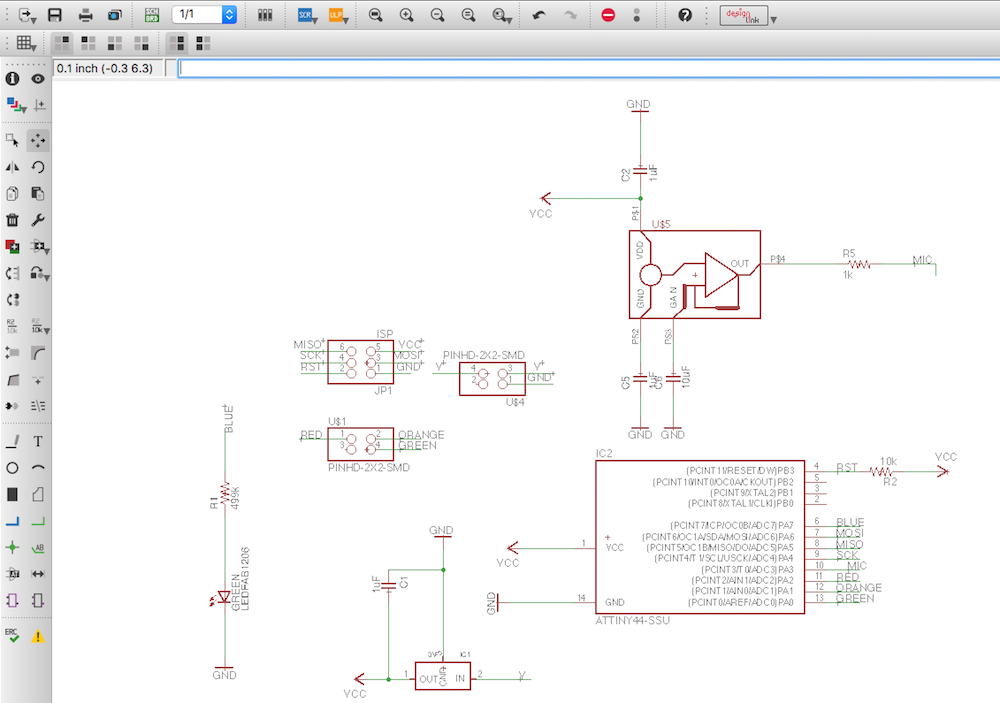
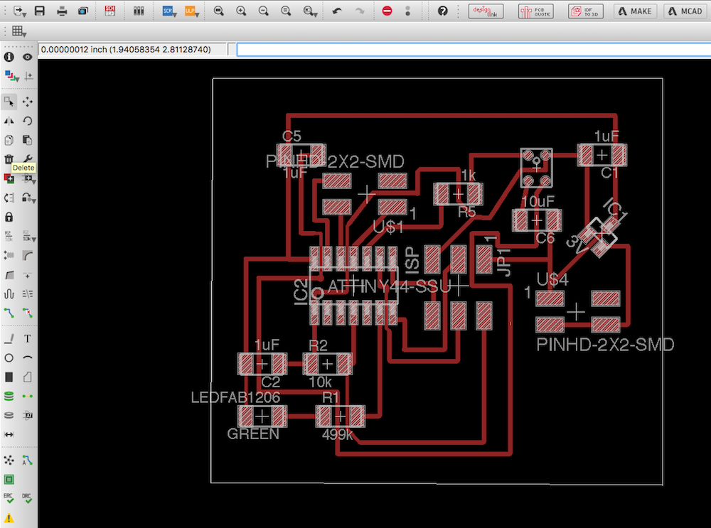
I designed the board in Eagle, adding several extra pins which I can use later.
I did not noticed that after restarting Eagle the Clearance in the Design Check Rules was set to 8mil instead of 16mil I had though I was using, so when I got to creating traces in Fabmodules, I realized that they cannot be milled.
So I redesigned the board because this first design could not pass the clearance check.
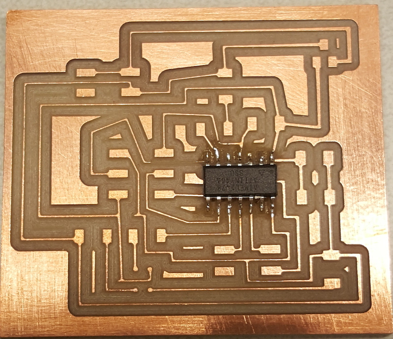
I had to mill the board twice because some of the traces on the first try did not come out well. This was most likely due to the uneven surface of the board.
However, once the board was done and I started soldering, I realized that our inventory does not have the same MEMS microphone as the one listed in the inventory. Instead of the 423-1134-1-ND with 4 pins, we had the one with 6 pins 423-1212-1-ND...
I still wanted to try working with the sound sensor, so now I had to redesign the whole layout to incorporate the electret microphone we did have in stock. The board I designed needs the following components:
- 1 microprocessor ATTINY44A-SSU-ND
- 1 electret microphone 668-1296-ND
- 1 Op-Amp AD8605ARTZREEL7CT-ND
- 1 Regulator LM3480IM3-5.0/NOPBCT-ND
- 1 LED
- 4 1uF capacitors
- 5 10k ohm resistors
- 1 1k ohm resistor
- 1 499 ohm resistors
- 1 2X3 pinheaders
- 2 2X2 pinheaders
I used the datasheet (pp. 144-149) to determine which pins I can use to connect Op-amp to the microcontroller (PA1 and PA0 both of which are capable of handling analog input).
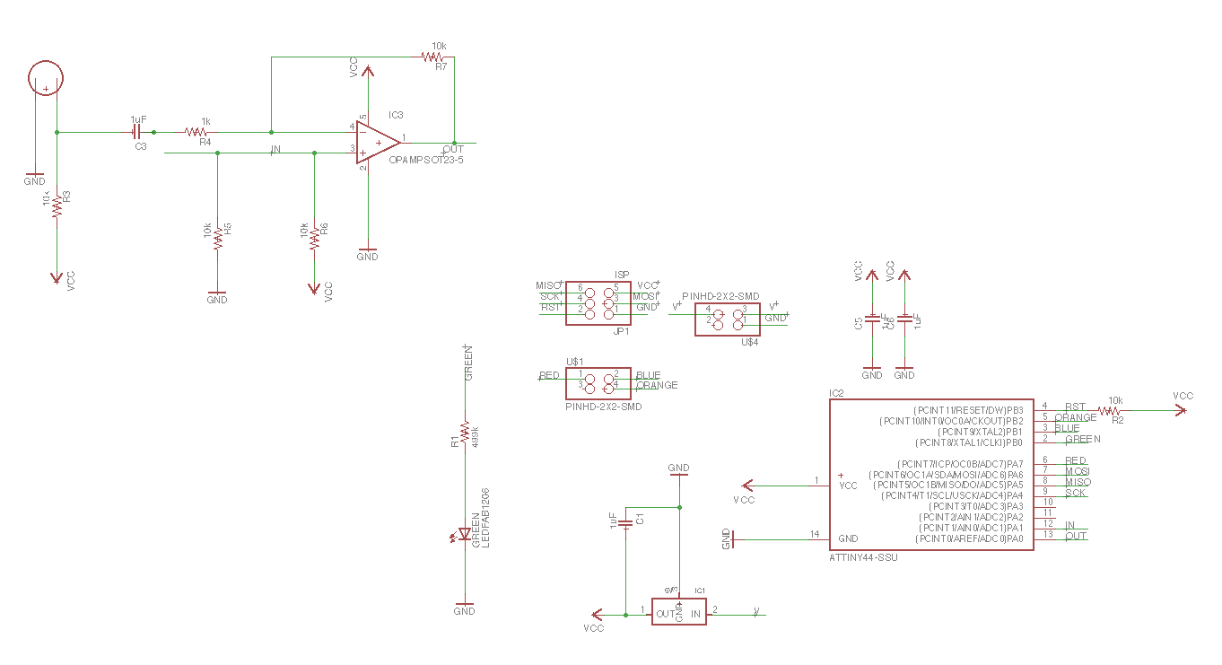
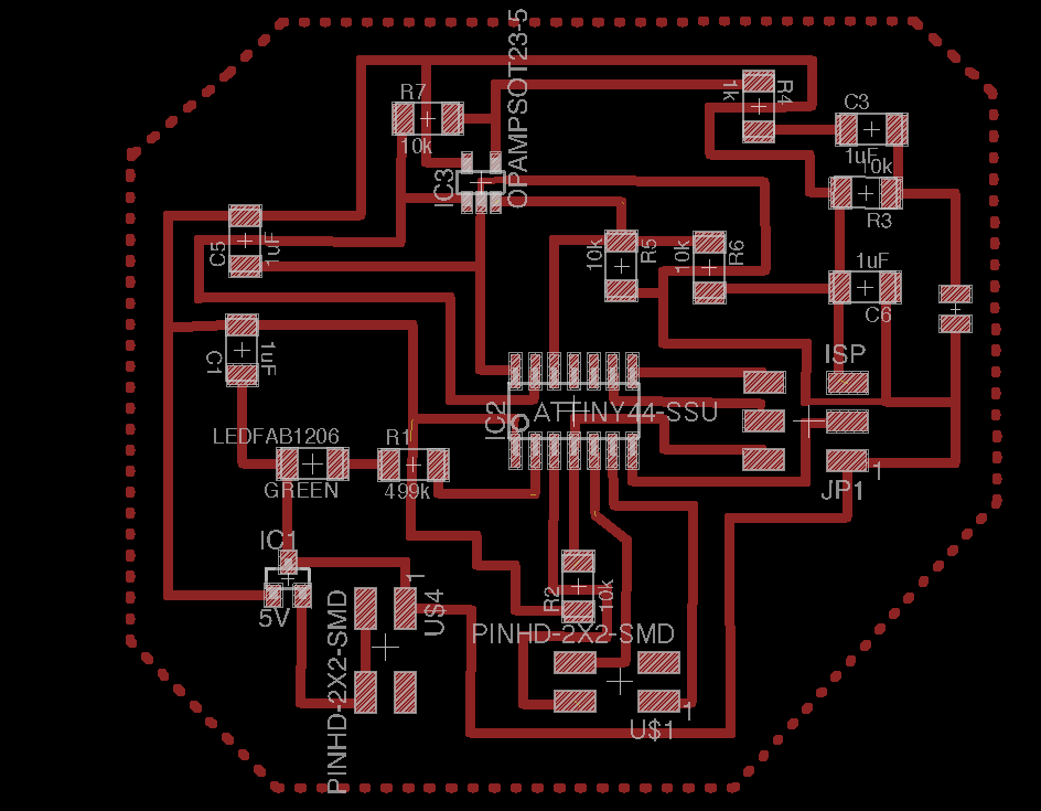
New schematic design
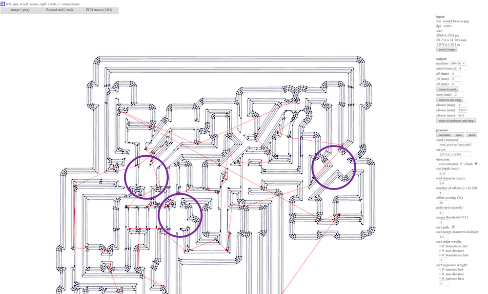
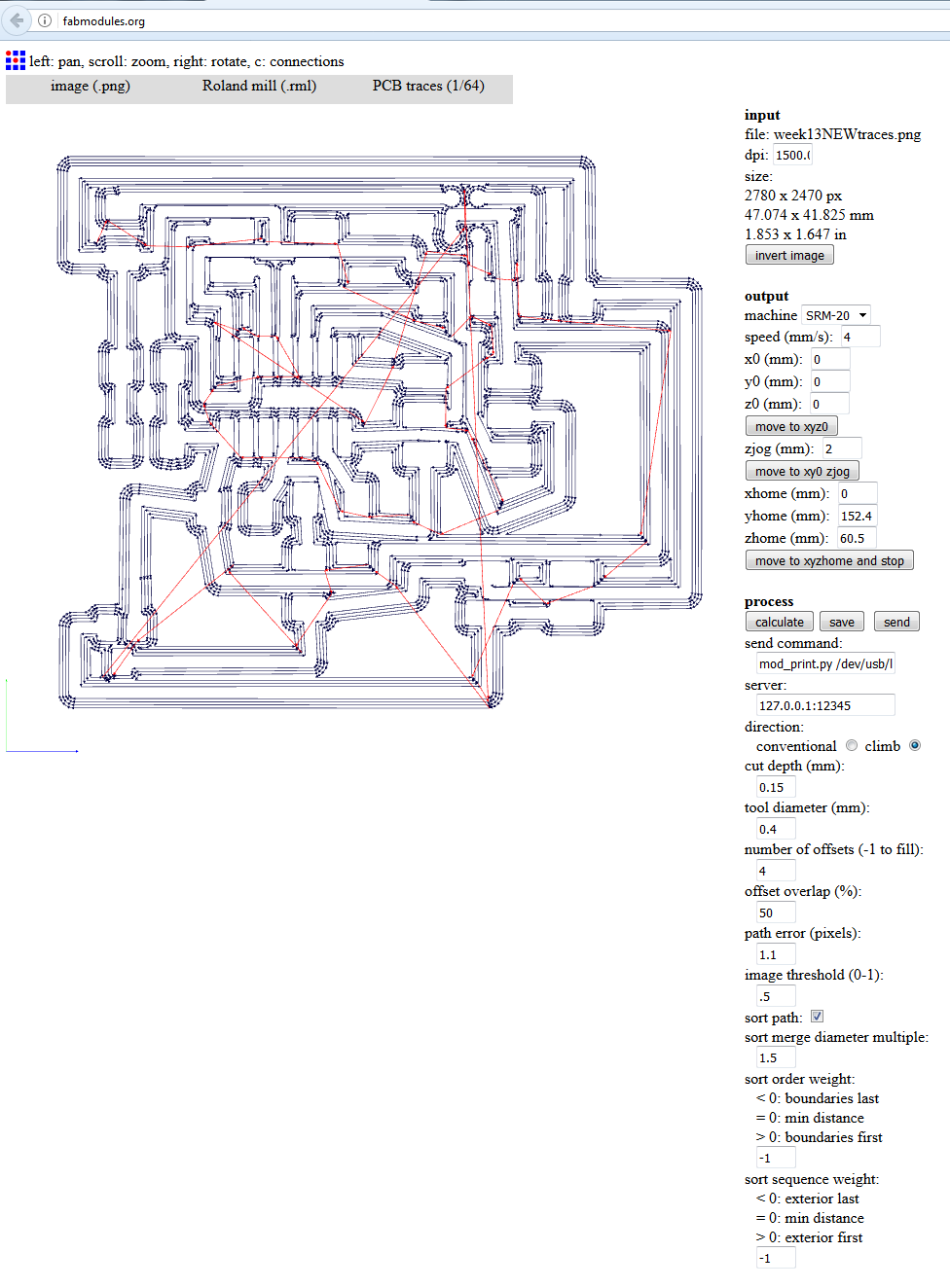
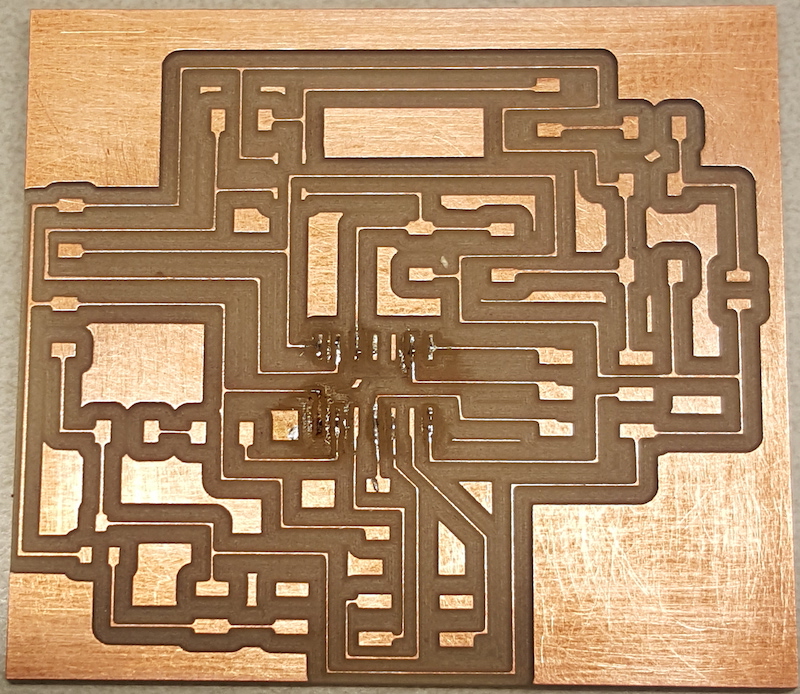
As always, I used Fabmodules to create traces and outline. I set the traces cut at 0.15, however, at the end the cut ended up being so deep that it affected the traces and they ended up being too thin even with the 16mil width design. I tried soldering the board, but I was not even able to attach the microcontroller since the traces burned from the heat of the soldering gun.
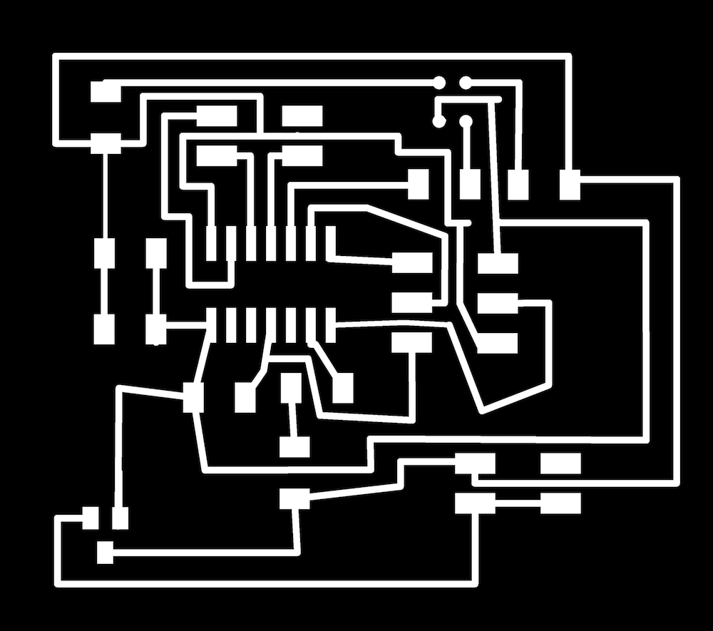
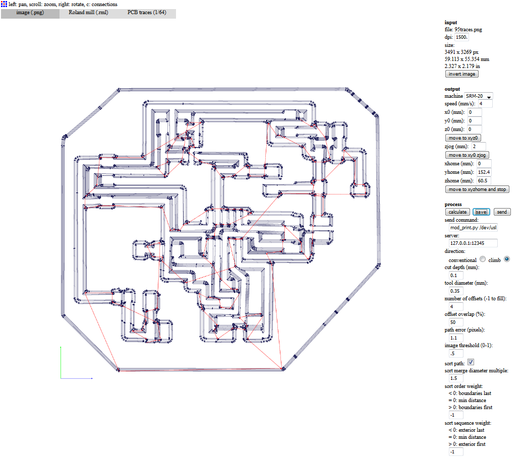
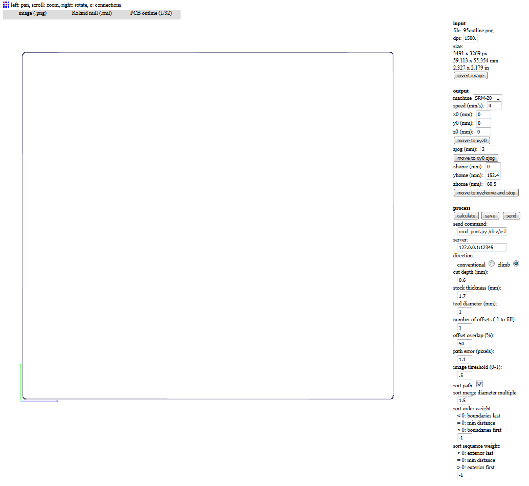
Without much hope ever milling a proper board for this week, I started designing another one. This time I tried using 24mil traces wherever possible. I also tried adding a ground polygon around the traces not to cut out parts of the board unless there is a need. This time I set the cut depth for traces at 0.1.
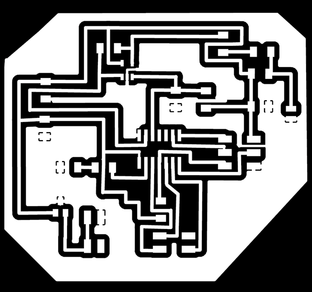
One more set of traces and outline
To my great surprise, the board was milled fine this time and even luckily soldering went fine, so I was all set with the board to program.
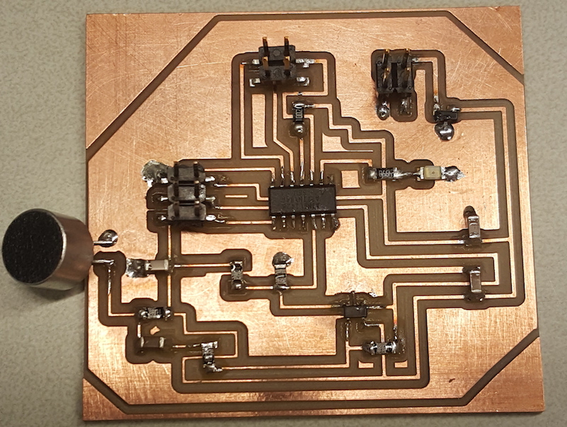
Finally, this looks promising...
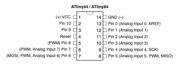
I used Arduino IDE which I already had setup for programming ATTiny44 with the ISP during week 8. I programmed the board to switch on and off the LED when the sound is sensed. To find the numbers of the LED pin PB0 and and the sensor input pin PA1 pins (10 and 0) for programming in Arduino, I used this reference found at hilowtech.org.
I Googled examples of how to read the electret microphone. I tried using analogRead() to get the sensor's mesurements, however I could not figure out the threshold of the sound level at which the LED could turn on. So I ended up using digitalRead() which worked.
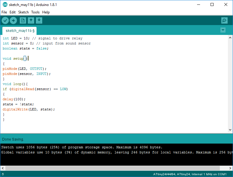
Final Code
And here is the result of this weeks labor
Files:
Eagle .sch and .brd files, Roland milling .rml traces and cutout files of the final successful design, Arduino source code file