pinout diagram
Embedded programming
This week the assignment was to:
ATtiny24/44/84 is a low-power CMOS 8-bit microcontroller based on the AVR enhanced RISC architecture. By executing powerful instructions in a single clock cycle, the ATtiny24/44/84 achieves throughputs approaching 1 MIPS per MHz allowing the system designer to optimize power consumption versus processing speed.
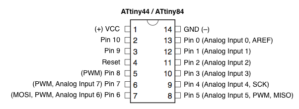
The attiny44 has a similar pinout as the attiny 84 and 24. below is a picture of the pinout diagram
pinout diagram
My aim was to program with as many environments as possible and as many languages as possible. some of the environments i tried are:
To install arduino ide in ubuntu 16.0 i used the command
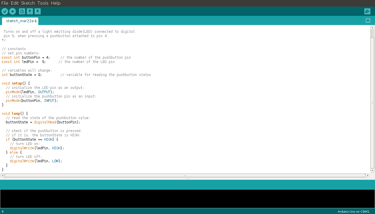
sudo apt-get update && sudo apt-get install arduino arduino-coreI set on to test the two IDEs (arduino and Eclipse). i wrote a sketch on Arduino as follows. It was pretty straightforward .The eclipse IDE however posed a lot of challenges since it did not have all the required plugins. The arduino sketch set the 4th pin as the pushbutton pin and the 5th one as the led pin. it then sets the led pin as output and the button pin as input. In the main loop the code is set to check if the button pin is high (pressed) to turn on the led otherwise the led stayed off
programming with arduino
programming with eclipse

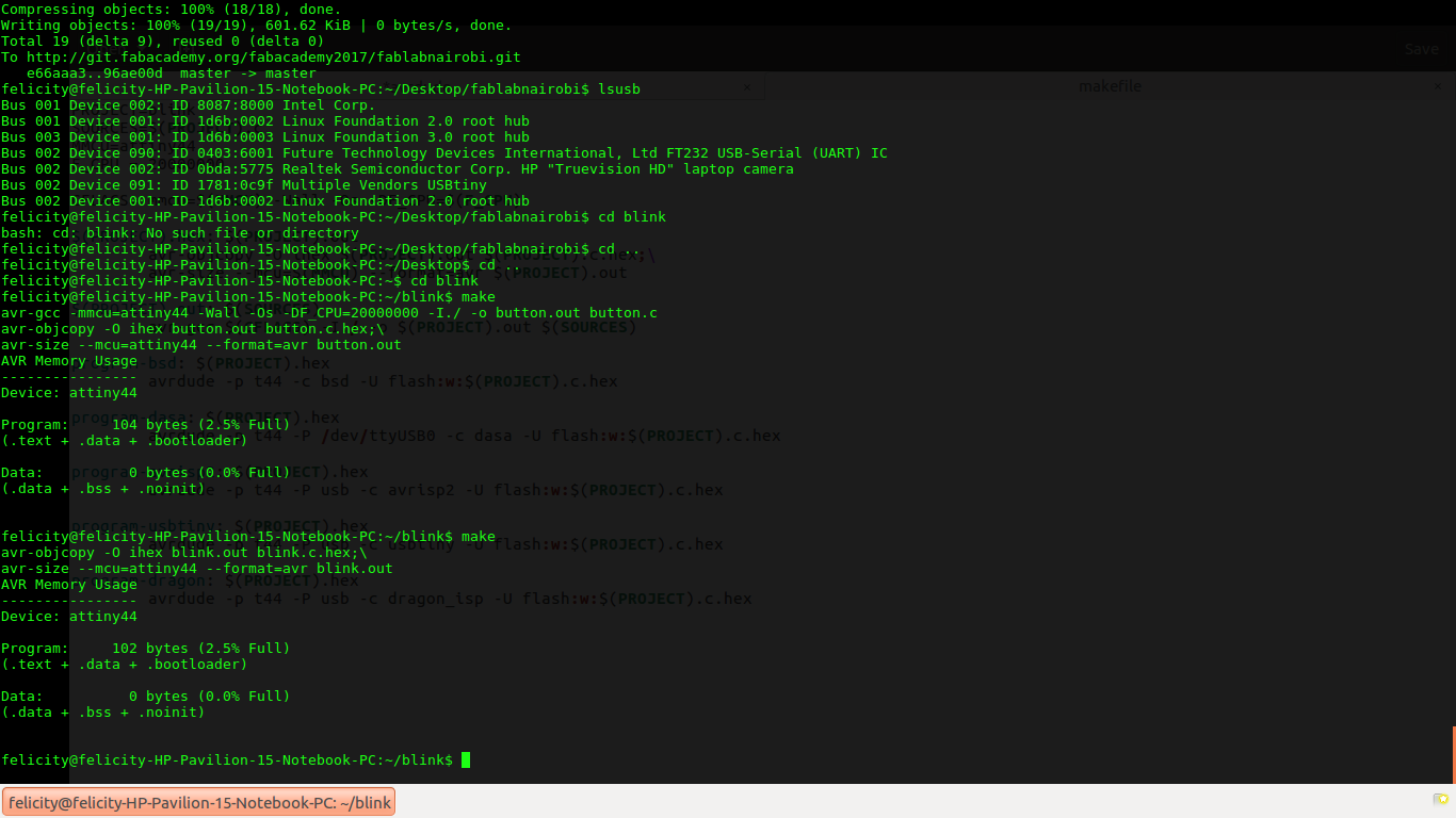
I found Gcc a good platform to use for programming especially on linux. I simply wrote my code on a text editor and saved it as a .c file. I also wrote a makefile for the program. I saved both files in one folder. I then entered that directory using terminal. and typed the make command. Running this command creates a hexadecimal file with the suffix .hex which can now be uploaded using the command below
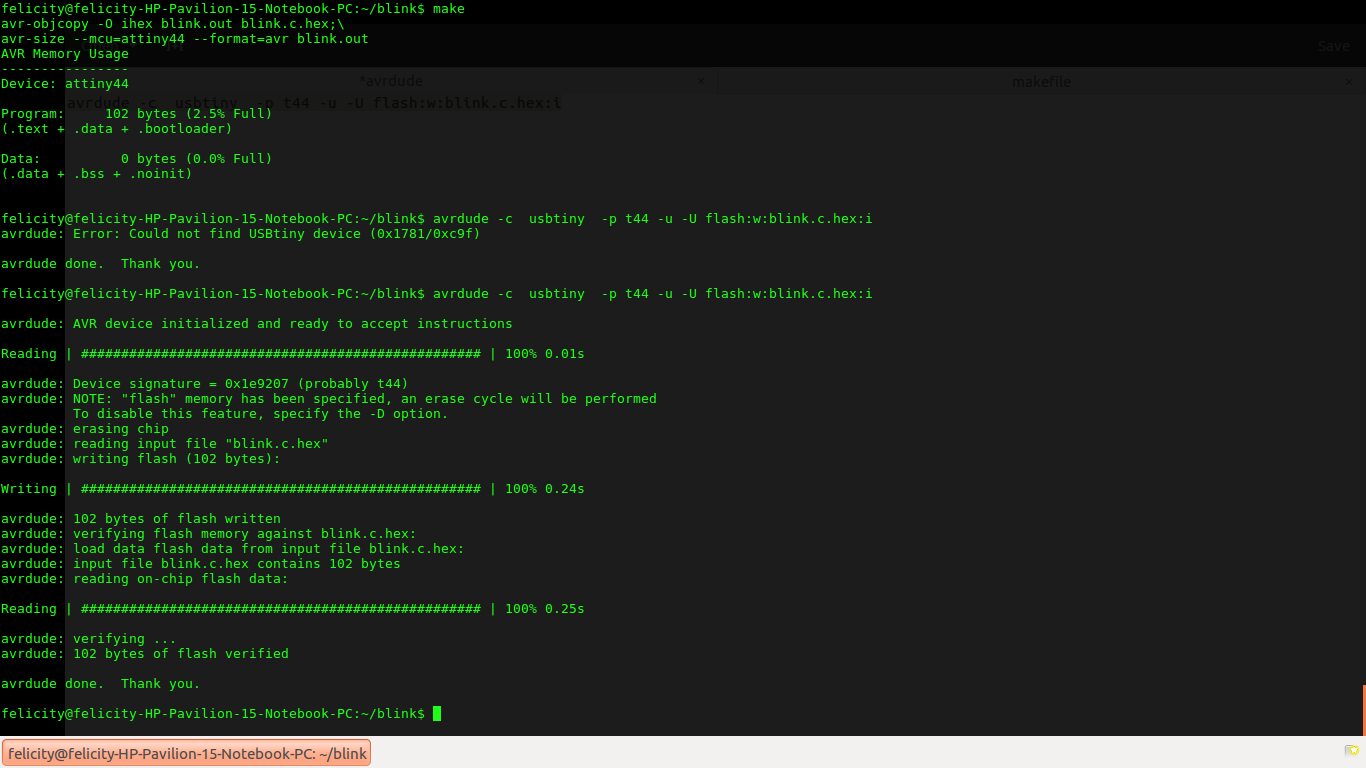
avrdude -c usbtiny -p t44 -u -U flash:w:blink.c.hex:i
-c: This is the programmer used. in my case i used fabisp so i wrote usbtiny
-p: This denotes the type of chip you are programming. the attiny44 is denoted using t44
-u: represents the type of memory which in this case is flash memory.
The file name is blink.c.hex and the command is terminated using the :i.
Terminal output after typing the make command
Terminal output after program upload
#include <avr/io.h>
#include<util/delay.h>


int main (void)
{
DDRB = 0b00000100;

//create an infinite loop
while(1) {

//turns B2 HIGH
PORTB =0b00000100;
//PAUSE 100 miliseconds
_delay_ms(100);

//turns B2 LOW
PORTB= 0b00000000;
//PAUSE 100 miliseconds
_delay_ms(100);
};
}
The program for blinking the led is written i c language. since the led is connected to pin 2 on port b i used the following command to turn it on which sets PB2 to high
PORTB =0b00000100; //turns B2 HIGH

_delay_ms(100); //PAUSE 100 miliseconds
To turn the led off is controlled by the code segment below which sets PB2 to zero
PORTB= 0b00000000; //turns B2 LOW
//PAUSE 100 miliseconds
_delay_ms(100);
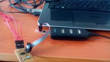
loading program using fab isp
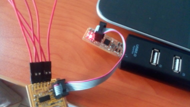
connection
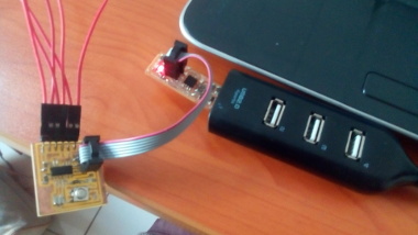
connection
I then went on to program the button so that it can control the led. Unfortunately i had connected the button to pin4 which is the RESET pin. The outcome was not as expected. The led went off when the button was pressed instead of blinking faster. Check the video below.
To solve this problem i had to disable the reset pin. This i did by entering the following command.
avrdude -c avrispmkII -p t44 -u -U hfuse:w:0x5A:m
This brought the feedback below
felicity@felicity-HP-Pavilion-15-Notebook-PC:~$ avrdude -c avrispmkII -p t44 -u -U hfuse:w:0x5A:m -v

avrdude: Version 6.2
         Copyright (c) 2000-2005 Brian Dean, http://www.bdmicro.com/
         Copyright (c) 2007-2014 Joerg Wunsch

         System wide configuration file is "/etc/avrdude.conf"
         User configuration file is "/home/felicity/.avrduderc"
         User configuration file does not exist or is not a regular file, skipping

         Using Port                    : usb
         Using Programmer              : avrispmkII
avrdude: usbdev_open(): Found AVRISP mkII, serno: 000200066355
         AVR Part                      : ATtiny44
         Chip Erase delay              : 4500 us
         PAGEL                         : P00
         BS2                           : P00
         RESET disposition             : possible i/o
         RETRY pulse                   : SCK
         serial program mode           : yes
         parallel program mode         : yes
         Timeout                       : 200
         StabDelay                     : 100
         CmdexeDelay                   : 25
         SyncLoops                     : 32
         ByteDelay                     : 0
         PollIndex                     : 3
         PollValue                     : 0x53
         Memory Detail                 :

                                  Block Poll               Page                       Polled
           Memory Type Mode Delay Size  Indx Paged  Size   Size #Pages MinW  MaxW   ReadBack
           ----------- ---- ----- ----- ---- ------ ------ ---- ------ ----- ----- ---------
           eeprom        65     6     4    0 no        256    4      0  4000  4500 0xff 0xff
           flash         65     6    32    0 yes      4096   64     64  4500  4500 0xff 0xff
           signature      0     0     0    0 no          3    0      0     0     0 0x00 0x00
           lock           0     0     0    0 no          1    0      0  9000  9000 0x00 0x00
           lfuse          0     0     0    0 no          1    0      0  9000  9000 0x00 0x00
           hfuse          0     0     0    0 no          1    0      0  9000  9000 0x00 0x00
           efuse          0     0     0    0 no          1    0      0  9000  9000 0x00 0x00
           calibration    0     0     0    0 no          1    0      0     0     0 0x00 0x00

         Programmer Type : STK500V2
         Description     : Atmel AVR ISP mkII
         Programmer Model: AVRISP mkII
         Hardware Version: 1
         Firmware Version Master : 1.24
         Vtarget         : 5.2 V
         SCK period      : 8.00 us

avrdude: stk500v2_command(): command failed
avrdude: stk500v2_program_enable(): bad AVRISPmkII connection status: Unknown status 0x00
avrdude: initialization failed, rc=-1
         Double check connections and try again, or use -F to override
         this check.


avrdude done.  Thank you.
#include <avr/io.h>
#include < util/delay.h & gt

int main(void)
{
DDRB |= 1 << PINB2; // setting PB2 as output
DDRB &= ~(1 << PINB3); // setting PB3 as input
PORTB |= 1 << PINB3; // sets PB3 high

while (1)
{
PORTB ^= 1 << PINB2; // toggle on and off on PB2

if (bit_is_clear(PINB, 3)) //Button press
{
_delay_ms(10); //Fast
}
else
{
_delay_ms(100); //Slow, from previous
}
}
}
break it down the following are the segments of the code
Since the button is connected to PB3 i set this to input. i also set PB2(button pin) as output. In this code segment i have used a method called bit shifting whereby i shift a binary 1 or 0 to a pin in a port by using the OR |= 1 << PINB2; operation. For setting a pin as an output i shift a 1 to the location and perform an AND operation then take the compliment~(1 << PINB3) of the outcome in order to set it to 0
DDRB |= 1 << PINB2; // setting PB2 as output
DDRB &= ~(1 << PINB3); // setting PB3 as input
PORTB |= 1 << PINB3; // sets PB3 high
Here the code checks for a button press usind the line if (bit_is_clear(PINB, 3)) then it makes the blinking faster by setting the delay to 10 miliseconds. Otherwise the blink rate is 100 miliseconds. The code PORTB ^= 1 << PINB2; turns the led on and off by changing the state of PB2 high and low respectively
  while (1)
{
PORTB ^= 1 << PINB2; // toggle on and off on PB2

if (bit_is_clear(PINB, 3)) //Button press
{
_delay_ms(10); //Fast
}
else
{
_delay_ms(100); //Slow, from previous
}
}
After this the circuit responded as desired