STEP 1: DESIGN
Tools used: Inkscape, Corel Draw
For this assignment my software of choice was inkscape, an open source cross platform design software. I began with a simple design of a square and used the boolean difference tool to achieve a square with corrugated ends.
Parametric design
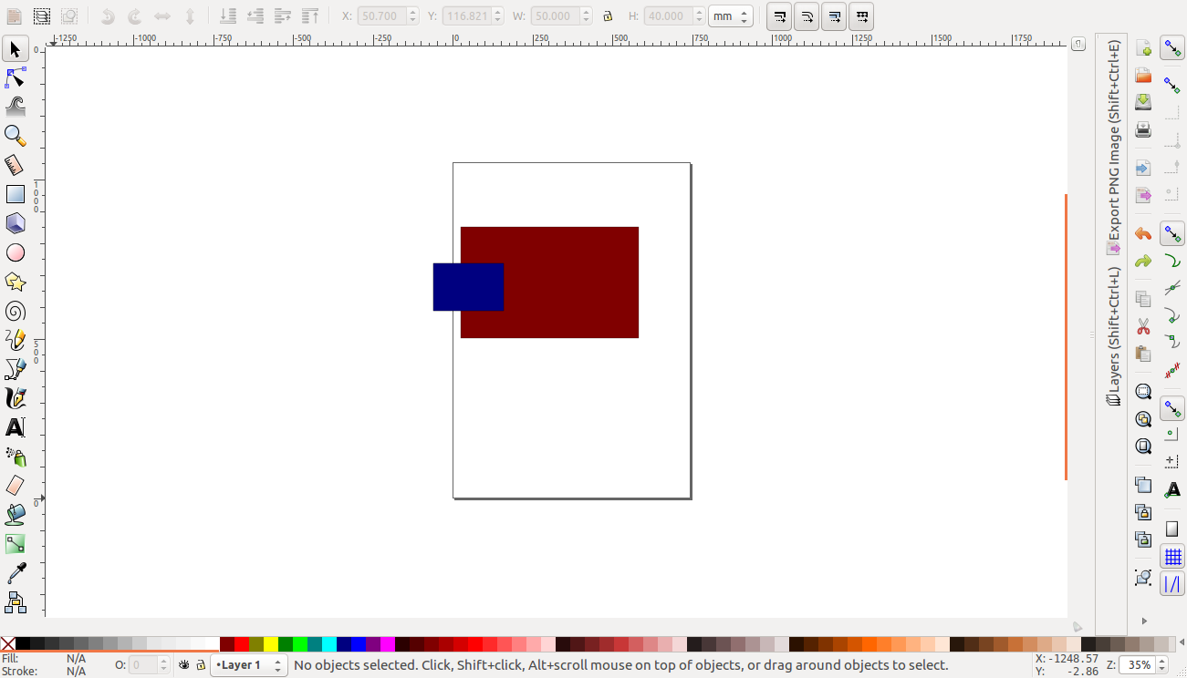
In this excercise i engaged parametric design by using the cloning method. I started with a large rectangle and a smaller rectangle that had the size of the slot i wanted to make. It is important for the rectangle to spill out of the main rectangle for best results.
First block
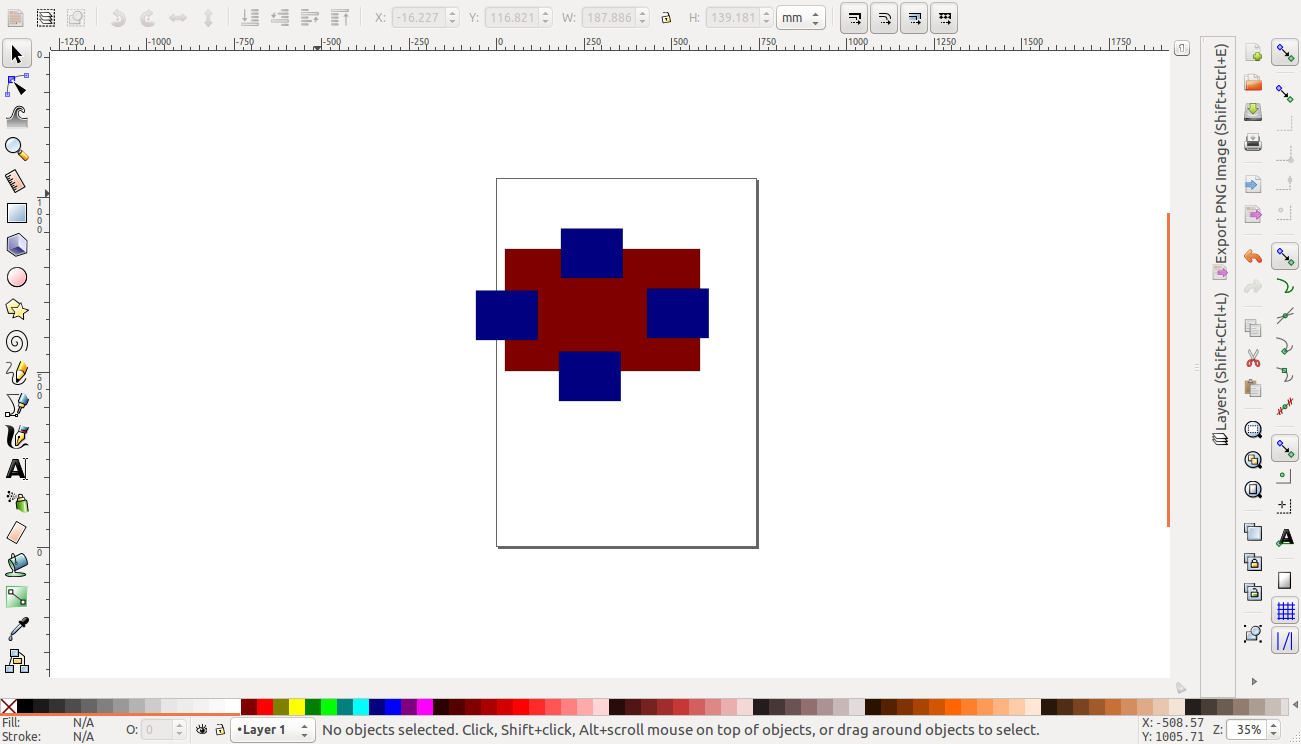
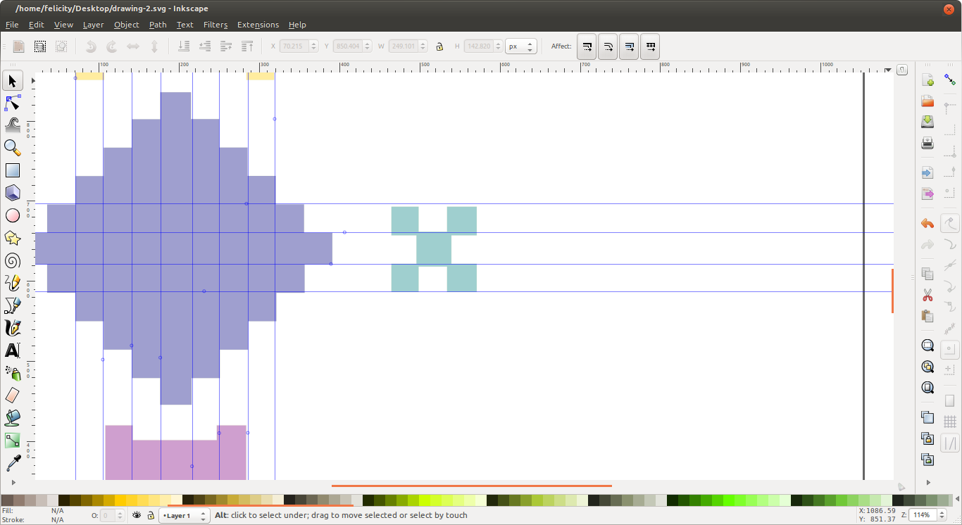
Then using the keyboard shortcut ALT+D I firmed clones of the rectangle. (NOTE: forming a clone of a clone is not advisable). These clones are placed in the places where the slots are expected as shown. the advantage of cloning is that whatever you do to the original affects the clones.
clones
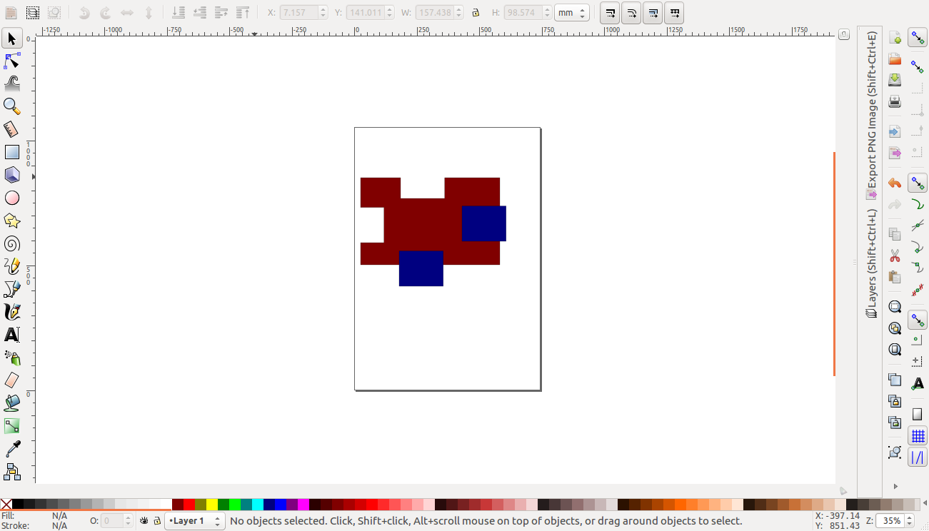
Now to create the slots i first selected the original (not clone) together with the big rectangle ang on the tool menu i chose path then difference. this created a gap in that area. I noticed however if i began with a clone the boolean difference would not occur.
clones
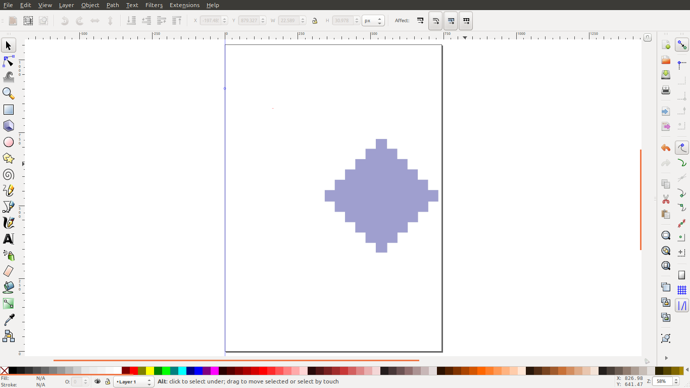
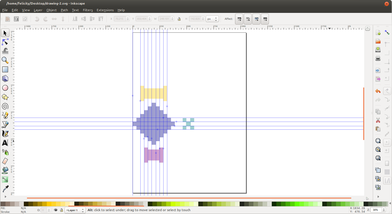
i used the same method to create the center piece
array of rectangles
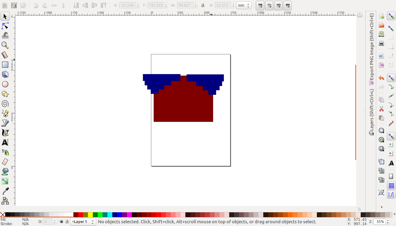
boolean subtraction
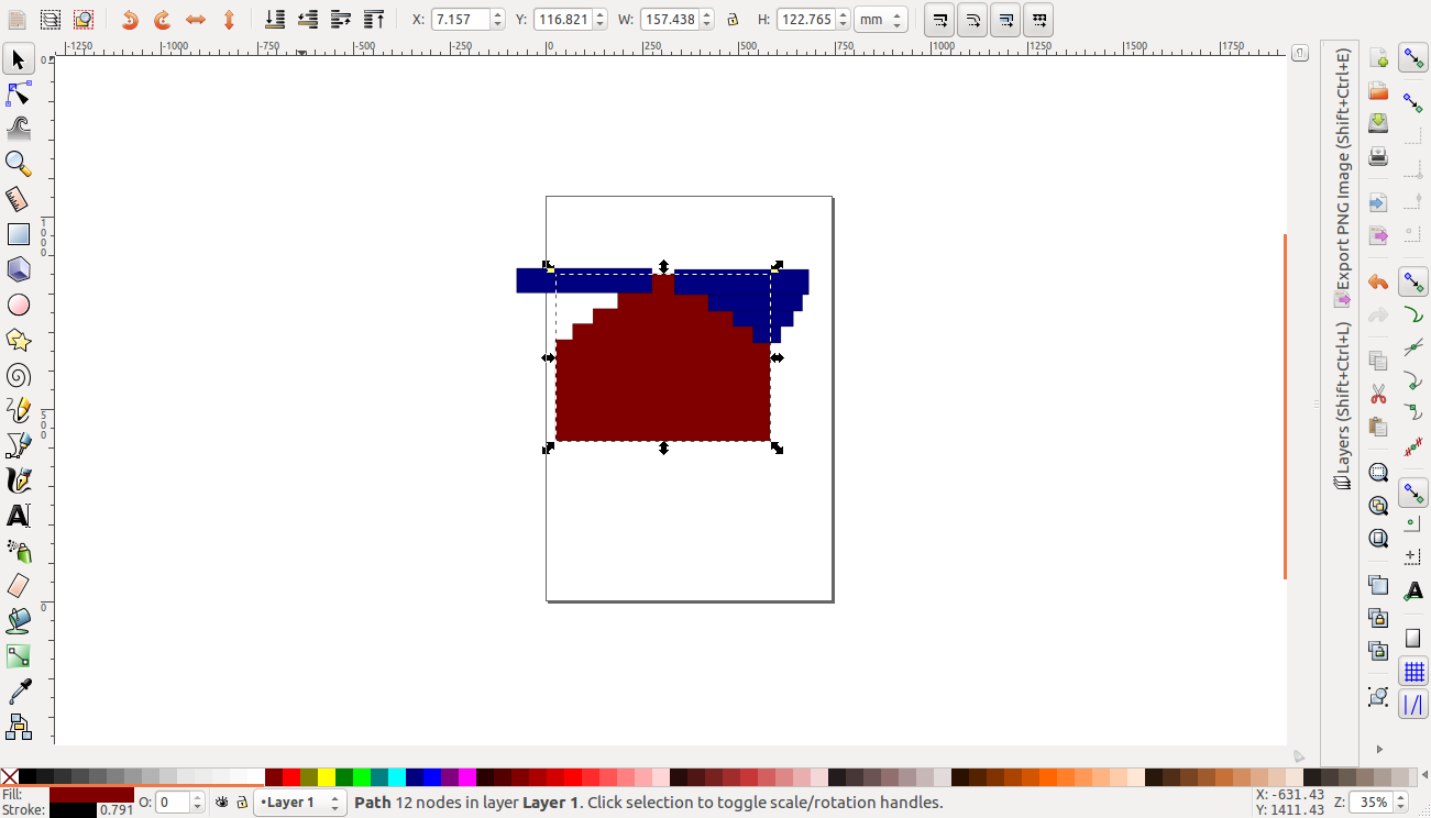
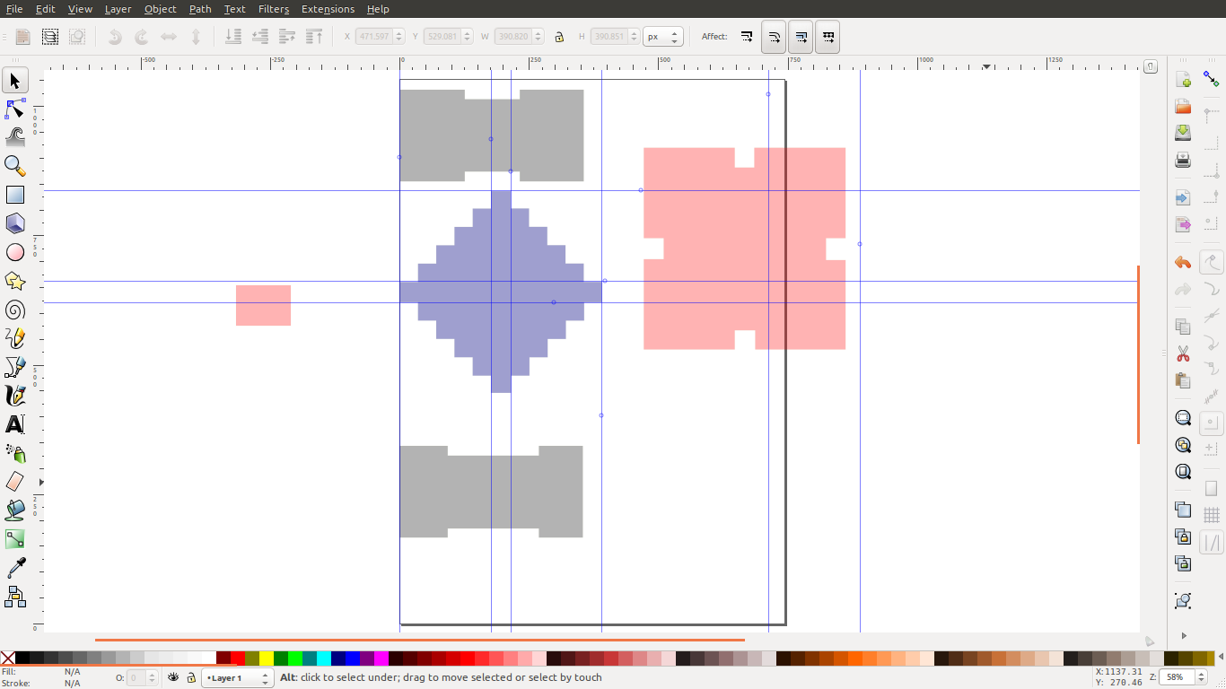
my idea was to make blocks that could be layered and also connected sideways. The first design i came up with is as shown below.
First block
With vertical connectors
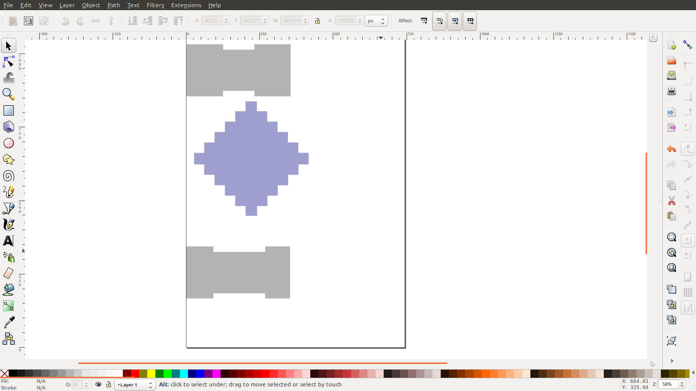
Adding a horizontal connector
Parametric design in onshape
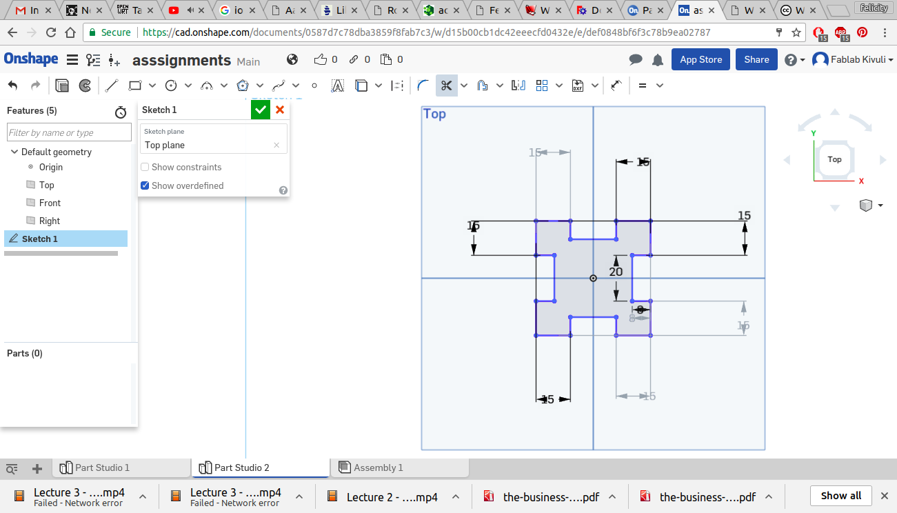
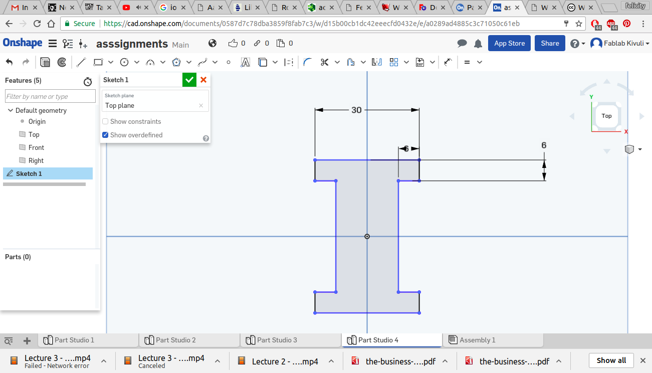
In order to better design parametrically i tested design on onshape software. Here i found that designing parametrically was more effective. I began with a simple rectangle as shown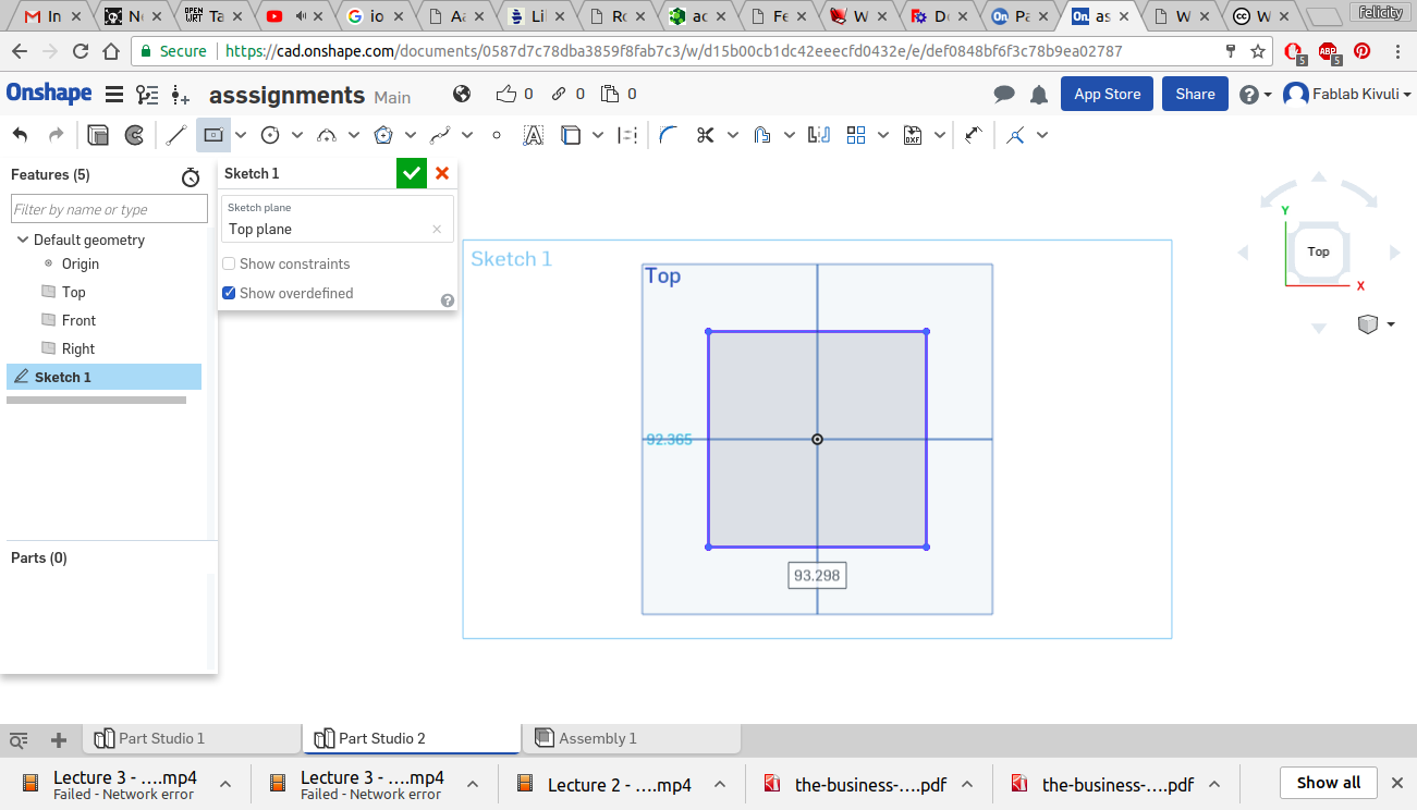
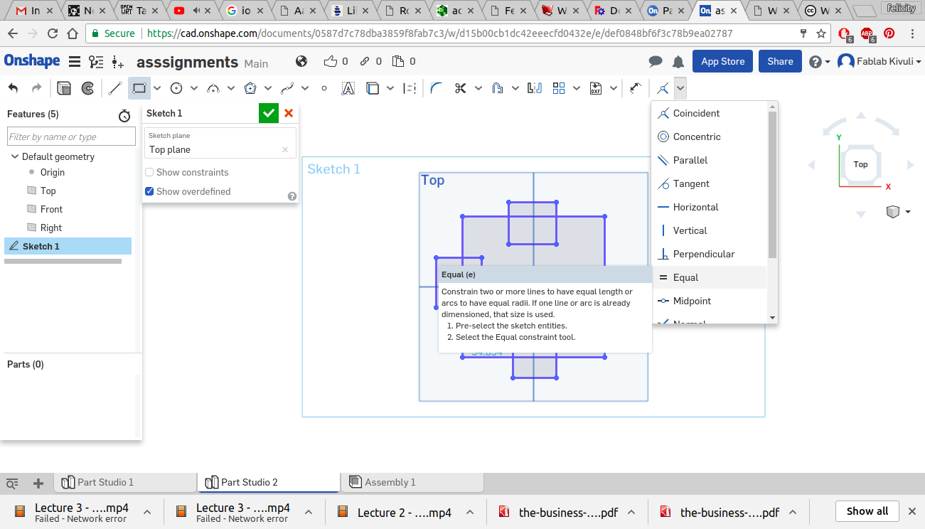
I then populated the rectangle with smaller rectangles around it as shown and put equality restraints to the rectangles that were to form the slots as shown.
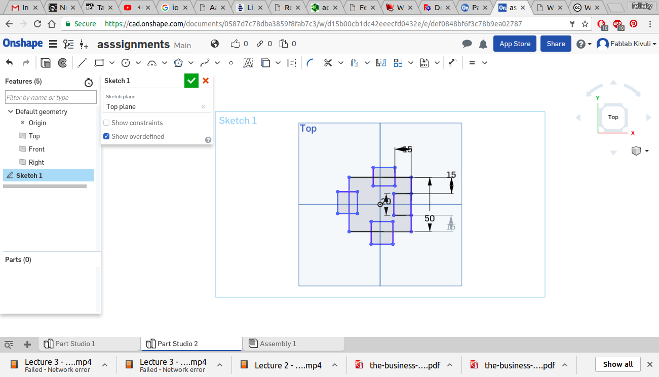
I then gave dimensions to the part as shown.
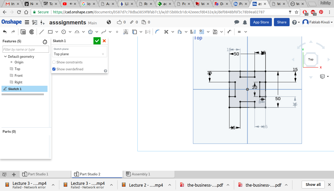
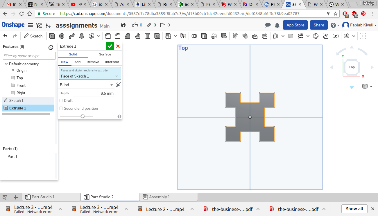
Using the trimming tool i cut off the unwanted lines in the sketch
To give it thickness i used the extrude tool and gave it a thickness of 6.5mm
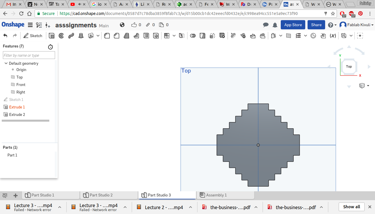
For the next piece i used a square and smaller rectangles tocreate the step-like design. i also used the equality constraint for the height of the rectangles
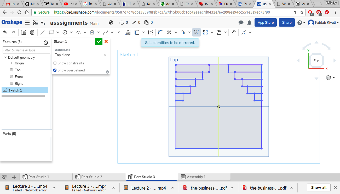
With the mirror tool i was able to replicate this pattern on the lower end of the square
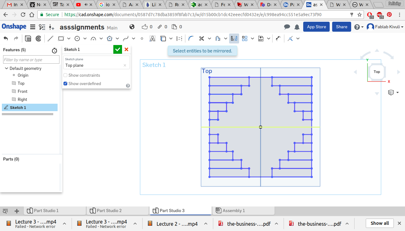
after trimming the unwanted lines i extruded the square and formed the second piece
For this piece i made a video to illustrate how changing the size of one piece affected the rest of the image.
Using the same principles i made the other pieces
I went on further to do an assembly to see how the pieces fit together
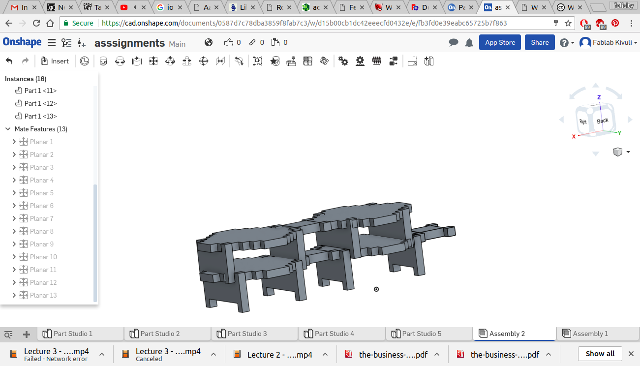
The design can be found in the cloud based software by following this link
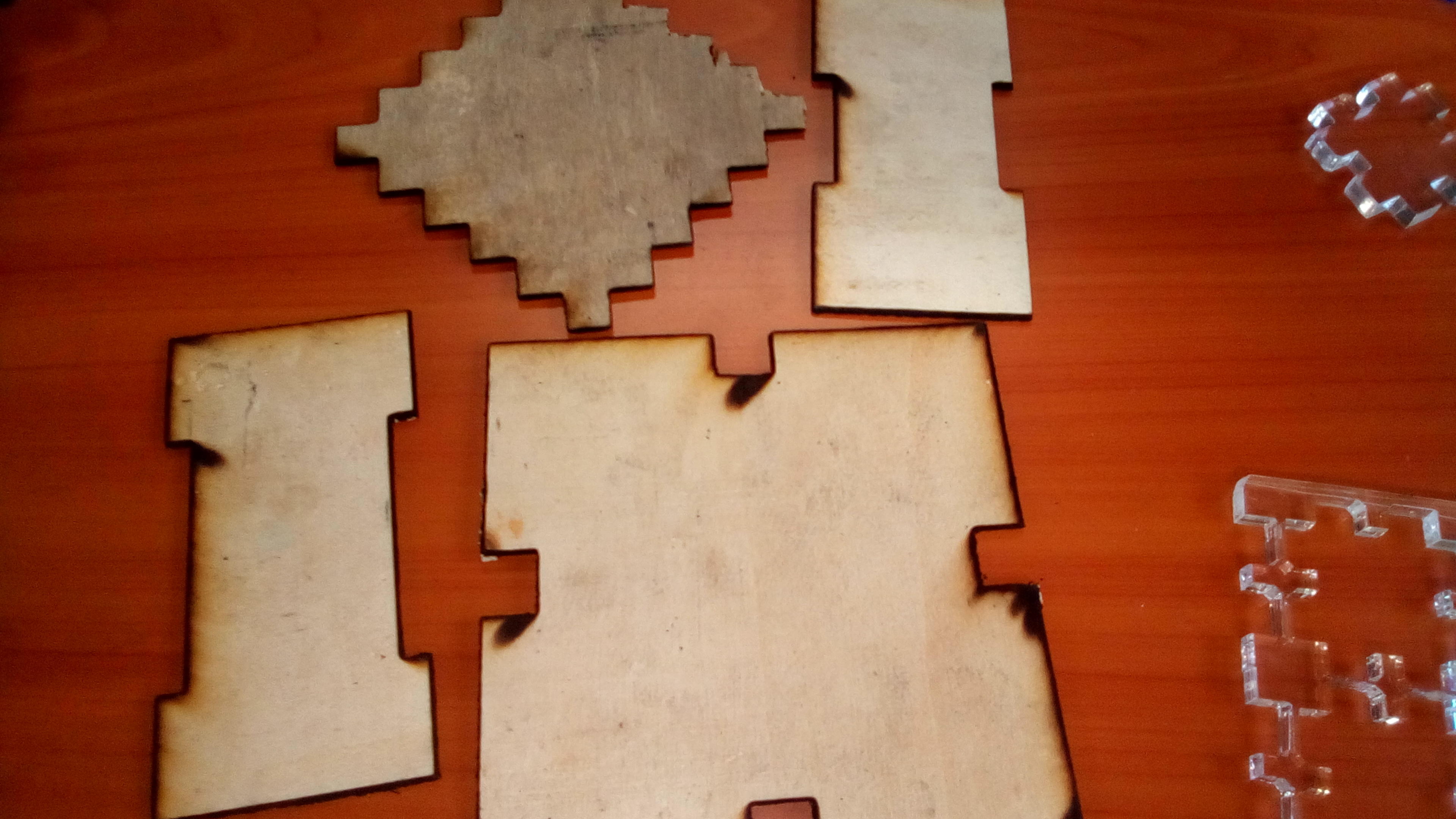
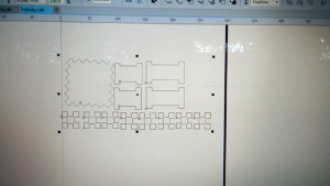
1.1. TEST CUT
In order to see if my design was workable i did a test cut of a few pieces on 3mm plywood. The results showed that the design needed some tweaking since the connecting blocks were too big.
1.2. FINAL DESIGN
Having established the parameters that need changing in the design i set off to redesign the parts and reduce the sizes accordingly. I reduced the height of the supporting vertical blocks to 40mm and the horizontal connecting block i changed to become a square of 3omm by 30mm. I however retained the middle jagged piece to remain the same.
First draft
final draft
1.3. Corel draw
In order to cut effectively with the laser cutter I needed to transfer my files to corel draw. I did this by exporting my designs from inkscape as a png file and importing that into corel draw. I then converted the bitmap to curves. i set a kerf of 0.2mm for my designs. This is mainly recomended for 3mm plywood however it worked for my designs.
Screenshot1
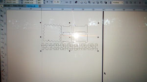
Screenshot2
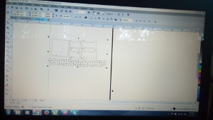
Screenshot3
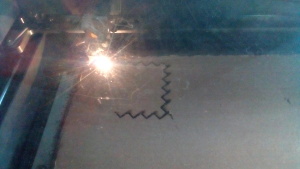
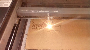
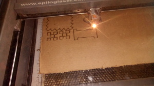
STEP 3: CUTTING
Tools used: LASER CUTTER, 6.7mm cardboard
Now that the files were ready for cutting, It was time to set up the laser cutter. my material of choice being 6mm cardboard, i had to try different power nad speed settings and finally i settled for power of 100%, Speed of 10% and a frequency of 500.
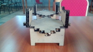
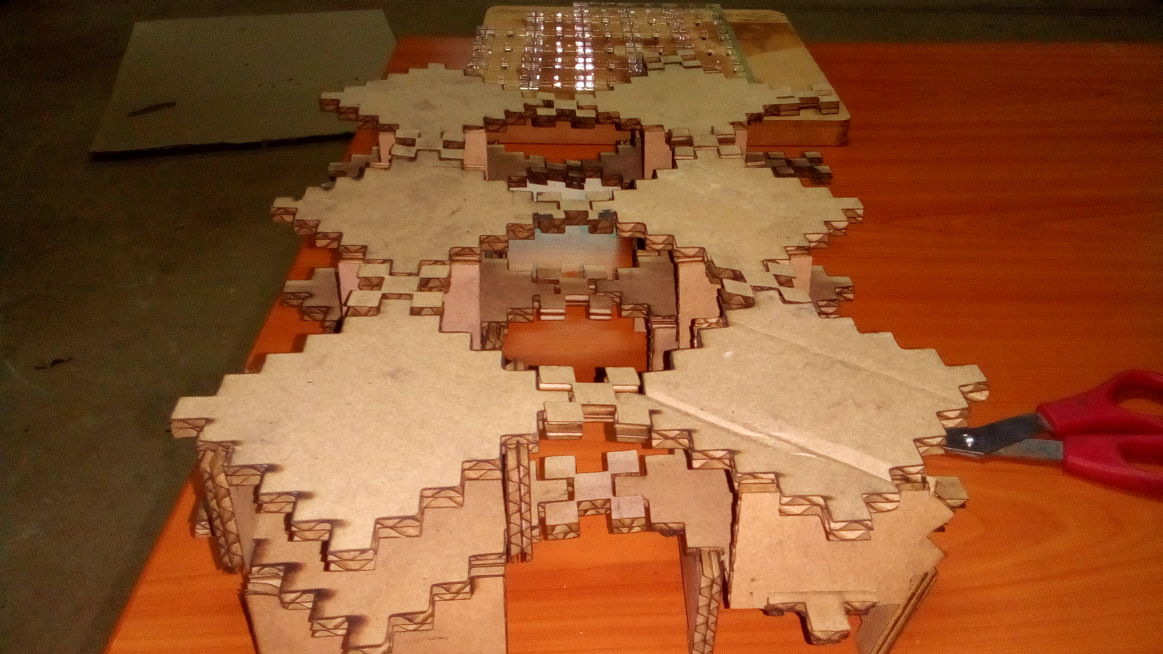
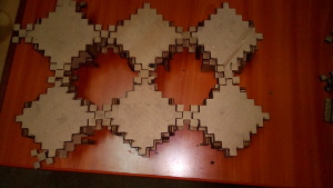
STEP 4: Assembly and experimentation
At this point it was time to experiment on the different shapes i could come uo with using the building blocks
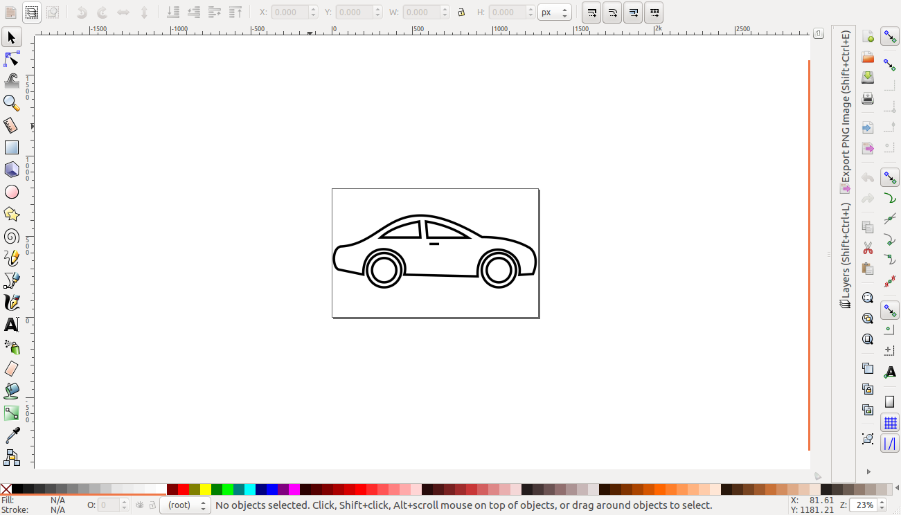
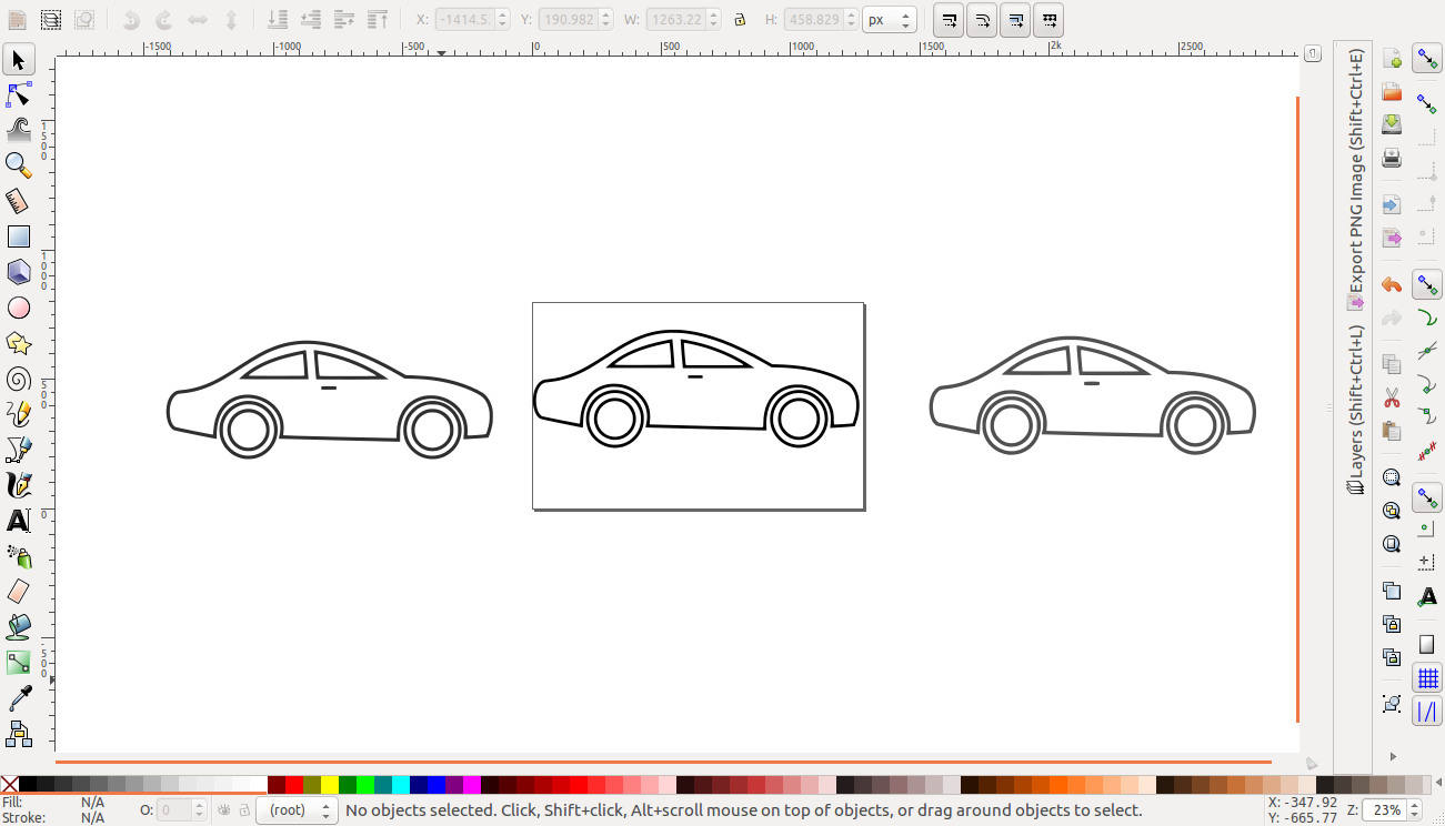
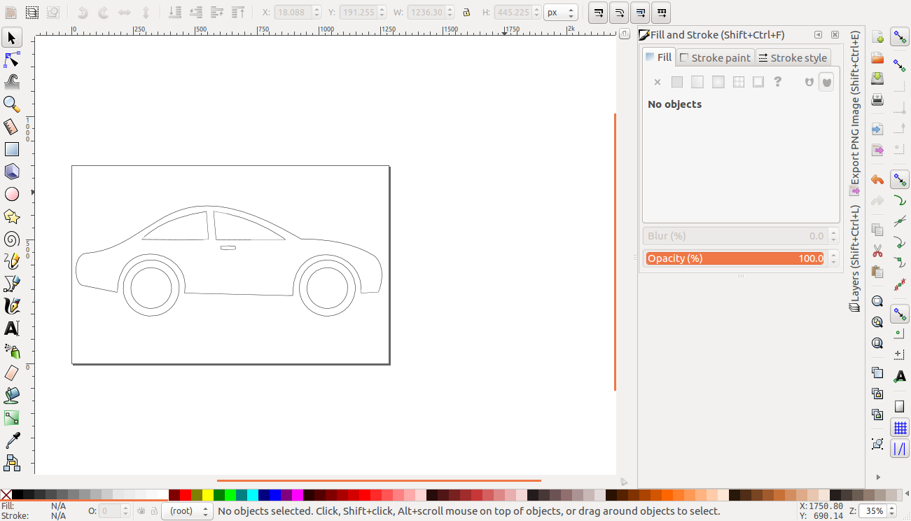
Vinyl cutting
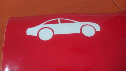
For the vinyl cutting excercise i chose to use a clip art of a car to make stickers for my final project design. I imported the clipart and began extracting the vectors by using the trace bitmap tool.
cutting
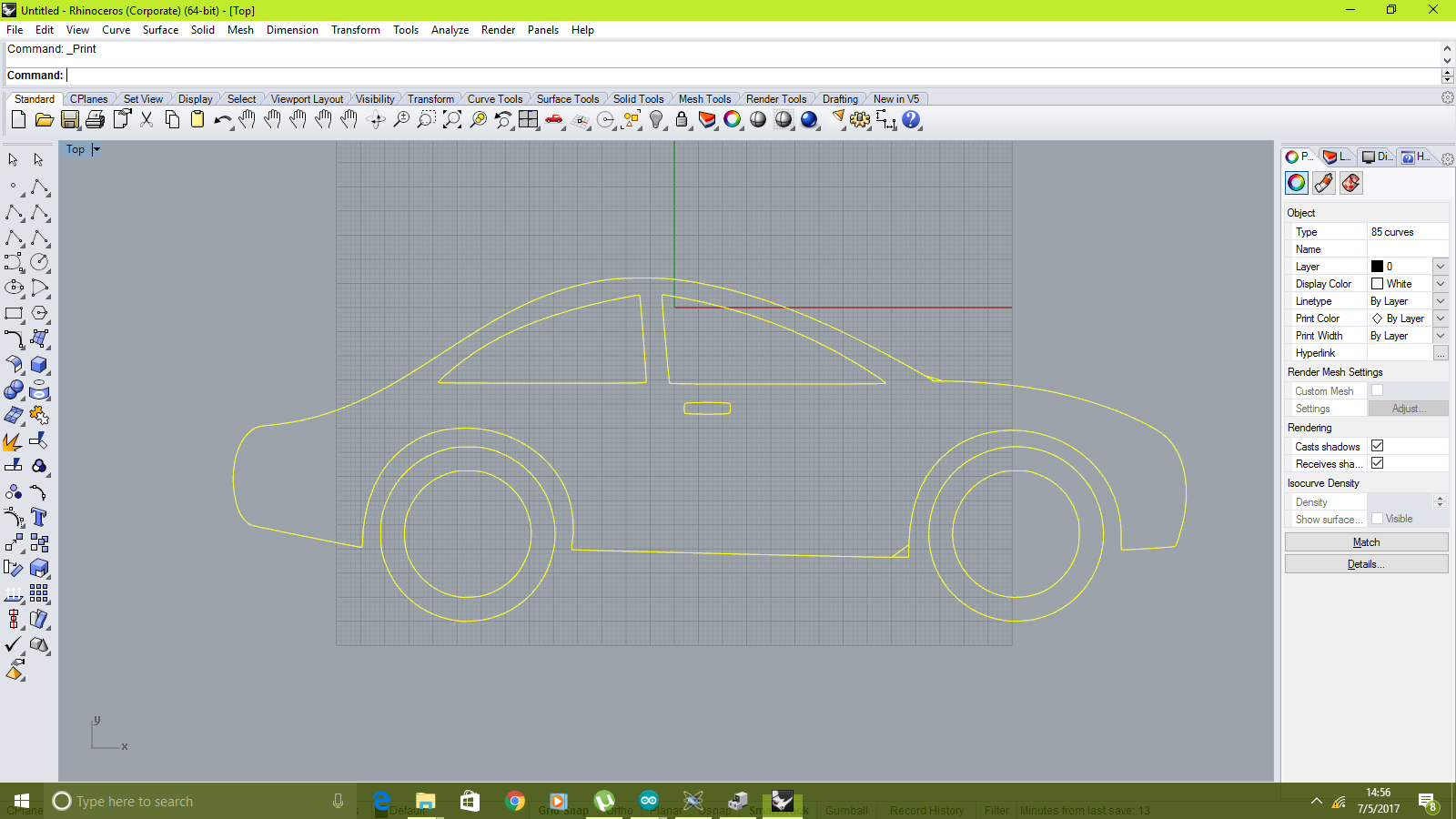
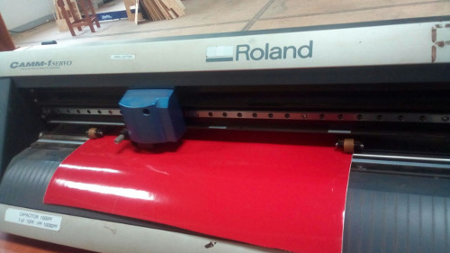
Working with the roland vinyl cutter was pretty straight forward. I loaded my file in dxf format to rhino, as shown. I then selected the print option and selected the drivers of the machine.
rhino
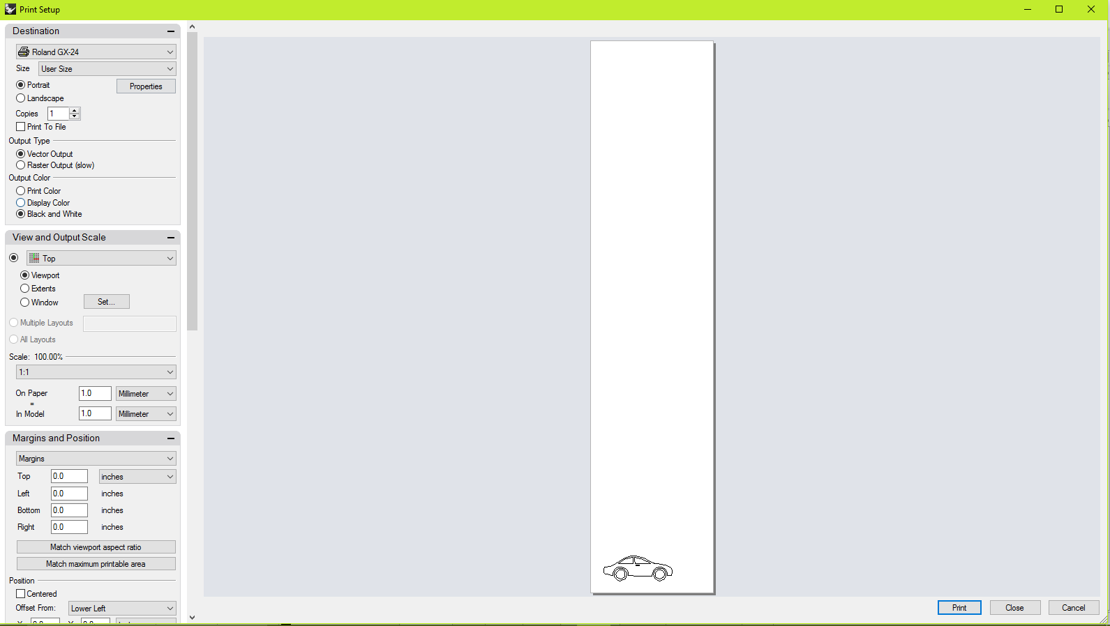
The printer options window appeared where different parameters such as force are set
printer parameters
The next step entails setting up the machne. setting the home and loading the vinyl roll and securing it.
material setup
The printing began soon after and this was the outcome after weeding
weeded
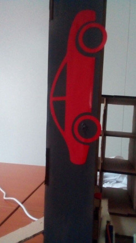
The sticker i stuck on one of the modules of my final project
sticker