Introduction
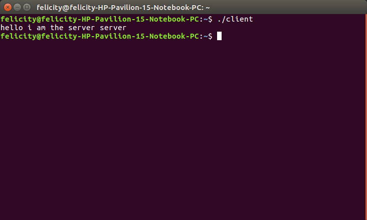
This week the assignment was to design and build a wired &/or wireless network connecting at least two processors . For this week I chose to work with sockets i used the socket family AF_INET6 address family. I came up with a script in c that acted as a server and a separae code that would be the client. The server sends a message to the client that says "hello i am the server"
The server
for the server i chose to use AF_INET which connects
with different machine as opposed to AF_UNIX which connects on the same machine
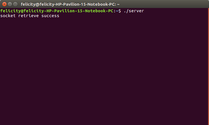
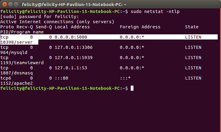
The server is using port 5000.
#include <sys/socket.h>
#include <netinet/in.h>
#include <arpa/inet.h>
#include <stdio.h>
#include <stdlib.h>
#include <unistd.h>
#include <errno.h>
#include <string.h>
#include <sys/types.h>

int main(void)
{
  int listenfd = 0,connfd = 0;

  struct sockaddr_in serv_addr;

  char sendBuff[1025];
  int numrv;

  listenfd = socket(AF_INET, SOCK_STREAM, 0);
  printf("socket retrieve success\n");

  memset(&serv_addr, '0', sizeof(serv_addr));
  memset(sendBuff, '0', sizeof(sendBuff));

  serv_addr.sin_family = AF_INET;
  serv_addr.sin_addr.s_addr = htonl(INADDR_ANY);
  serv_addr.sin_port = htons(5000);

  bind(listenfd, (struct sockaddr*)&serv_addr,sizeof(serv_addr));

  if(listen(listenfd, 10) == -1){
      printf("Failed to listen\n");
      return -1;
  }

  while(1)
    {
      connfd = accept(listenfd, (struct sockaddr*)NULL ,NULL); // accept awaiting request

      strcpy(sendBuff, "hello i am the server");
      write(connfd, sendBuff, strlen(sendBuff));

      close(connfd);
      sleep(1);
    }

  return 0;
}
The client
#include <sys/socket.h>
#include <sys/types.h>
#include <netinet/in.h>
#include <netdb.h>
#include <stdio.h>
#include <string.h>
#include <stdlib.h>
#include <unistd.h>
#include <errno.h>
#include <arpa/inet.h>

int main(void)
{
  int sockfd = 0,n = 0;
  char recvBuff[1024];
  struct sockaddr_in serv_addr;

  memset(recvBuff, '0' ,sizeof(recvBuff));
  if((sockfd = socket(AF_INET, SOCK_STREAM, 0))< 0)
    {
      printf("\n Error : Could not create socket \n");
      return 1;
    }

  serv_addr.sin_family = AF_INET;
  serv_addr.sin_port = htons(5000);
  serv_addr.sin_addr.s_addr = inet_addr("127.0.0.1");

  if(connect(sockfd, (struct sockaddr *)&serv_addr, sizeof(serv_addr))<0)
    {
      printf("\n Error : Connect Failed \n");
      return 1;
    }

  while((n = read(sockfd, recvBuff, sizeof(recvBuff)-1)) > 0)
    {
      recvBuff[n] = 0;
      if(fputs(recvBuff, stdout) == EOF)
    {
      printf("\n Error : Fputs error");
    }
      printf("\n");
    }

  if( n < 0)
    {
      printf("\n Read Error \n");
    }

  return 0;
}
compiling
To compile the code above i used the following commands
server
cc server.c -o server
client
cc client.c -o clientThis generated excecutable files in my home folder
Running the code
since both scripts were in the same computer i ran them on two different terminals using the commands below. As a rule the server should be run before the client.
Server
./server
Client
./client
The outcome
Server
Client
To test whether its working use the command
sudo netstat -ntlp
Testing
Asynchronous Serial communication(RS-232)
BACKGROUND
Asynchronous means that data is transferred without support from an external clock signal. This transmission method is perfect for minimizing the required wires and I/O pins.It is commonly used for one‐to‐one communication .There are many variants but the simplest uses just two lines, TX(transmit) and RX (receive).The transmission process involves sending data at a certain speed commonly known as baud rate(9600 baud, 1 bit=1/9600=0.104 mS)The transmit pin idles high (when no communication)and goes low for 1 bit (0 104 . mS).It sends out data, LSB first (7 or 8 bits). If needed,tThere may be a parity bit (even or odd – error detection). This is useful for errror detection on the receiving end. one may use a stop bit (or two)
For this project i chose to work with a board that communicates serially. for this i chose the hello.bus.45 bridge and node circuits
Bit banging
For this excercise the attiny45 chip is used which has no transmit or receive pins hence the serial UART communication is manually simulated using software. all the parameters (baud rate, start and stop bits,parity etc ) is done using lines of code.
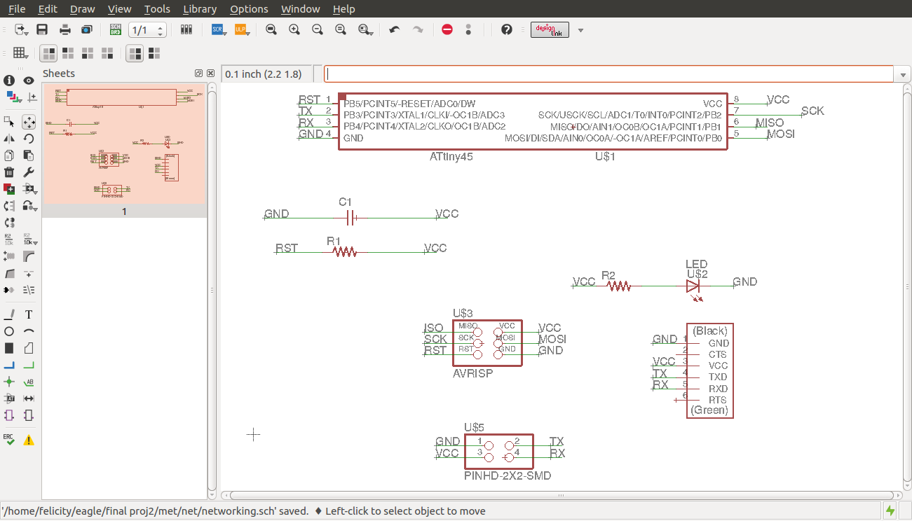
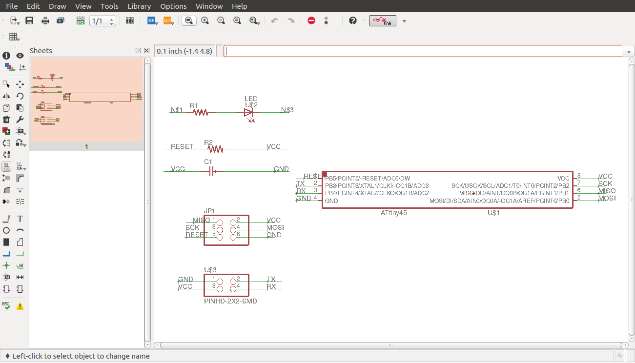
I did the design of the bridge on eagle as shown below
Bridge
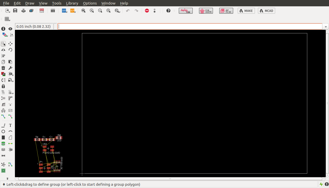
I then designed the board as shown
board view
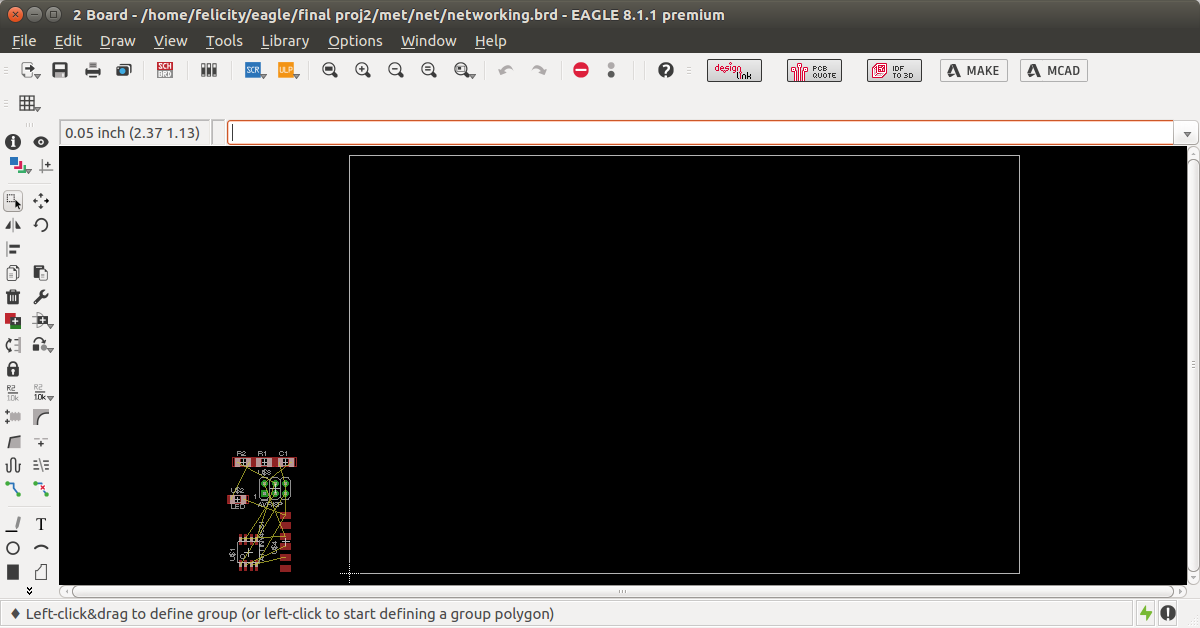
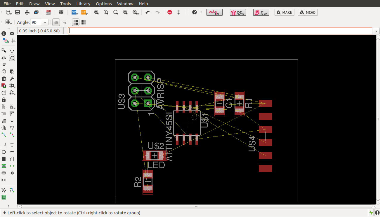
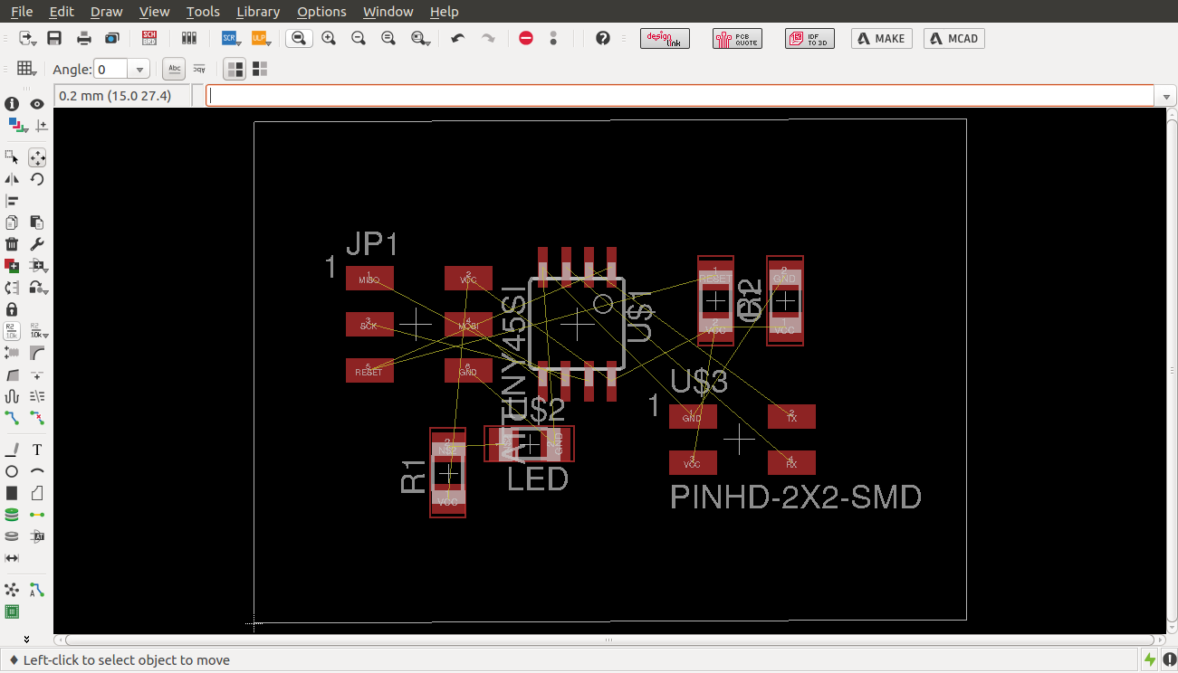
arranging components
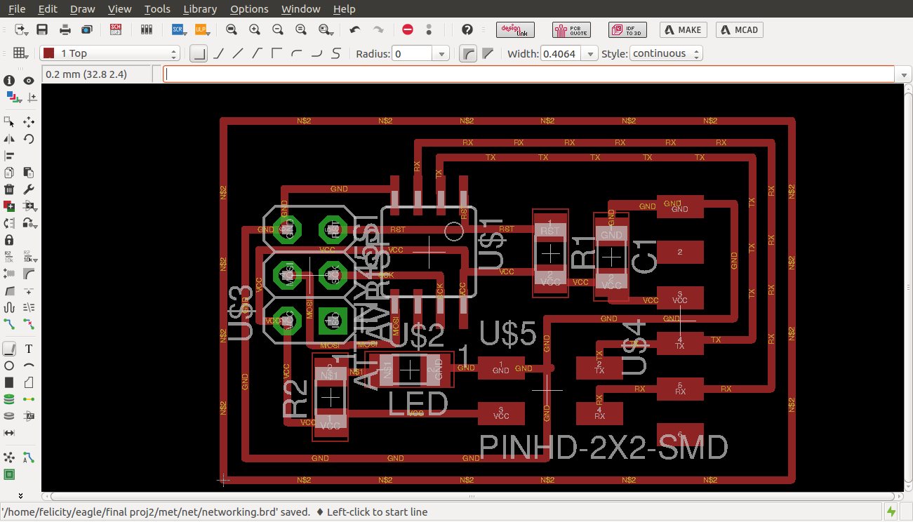
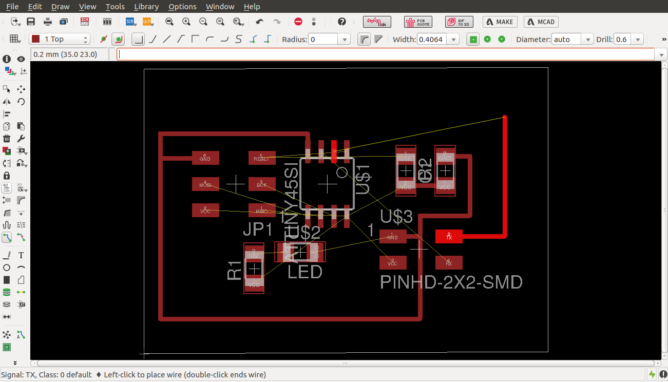
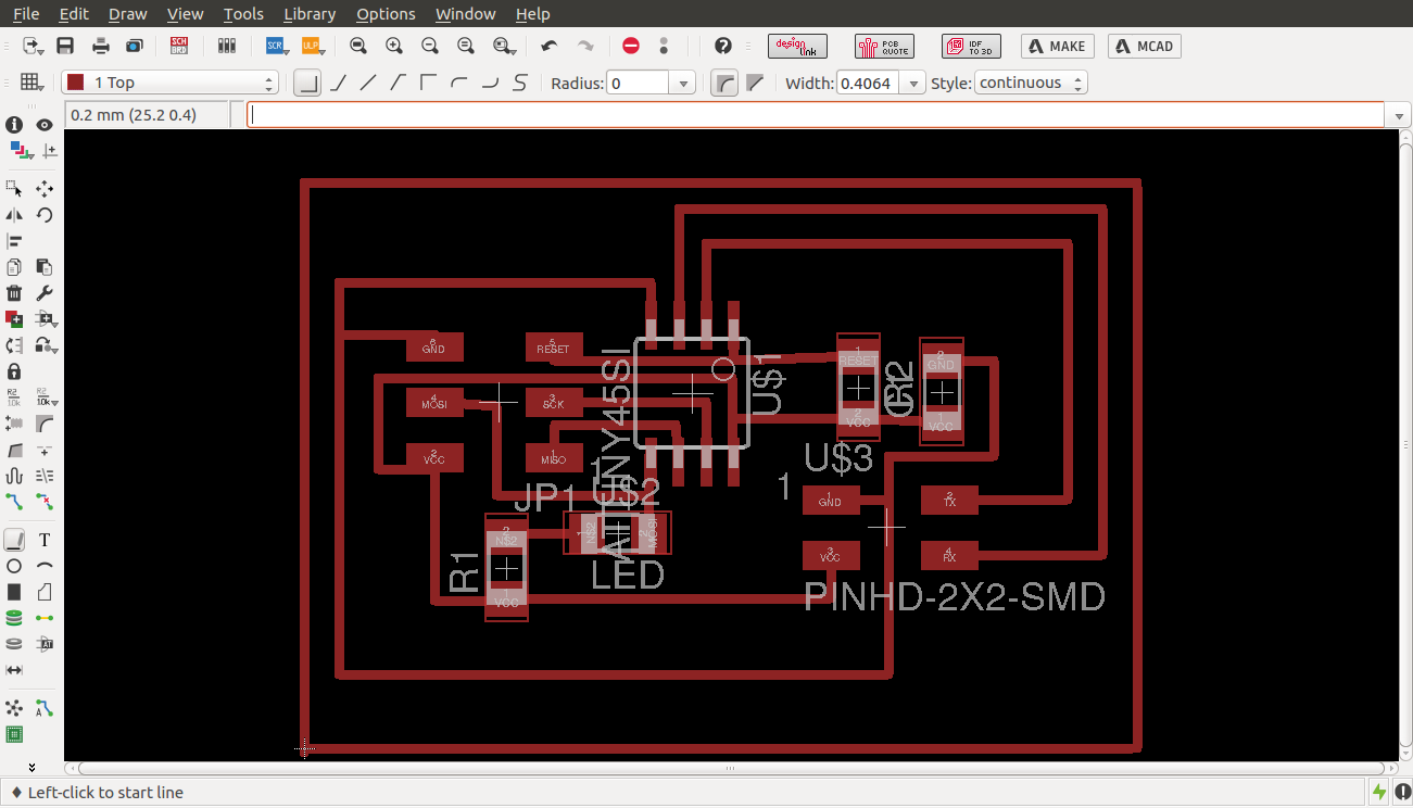
finished routing
Downloads
I then designed the node as shown
Node schematic view
I then designed the board as shown
board view
arranging components
routing
finished routing
Downloads
Etching
I set off production by downloading the traces in png format and printing them and fabricating the circuit by the process of etching. I then stuffed the circuit as follows


Safety
The etching process uses Ferric chloride and is fully automated with a timer and a pump. To ensure safety while handling the chemicals we use lab coats, rubber gloves and eye protection during the process. The etching station is next to a water source(sink) incase of spillages.
Disposal
To protect the environment We subcontract another company that specializes in disposal of ferrric chloride that comes every three months to collect the liquid and safely dispose of it.
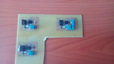
The stuffed board.
Debugging
To veryfy that my board was working i plugged it in with the fab isp programmer as shown. I however noticed that the leds on the programmer were both on and the one on the board. When i tried to upload code on the board i got an error message initialization failed, rc=-1 Double check connections and try again, or use -F to override this check. This meant checking all the connections with a multimeter and soldering dry joints. i found that one of the traces had shorted.
Testing
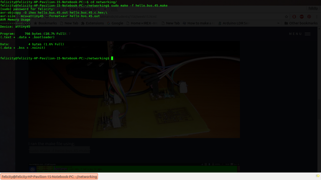
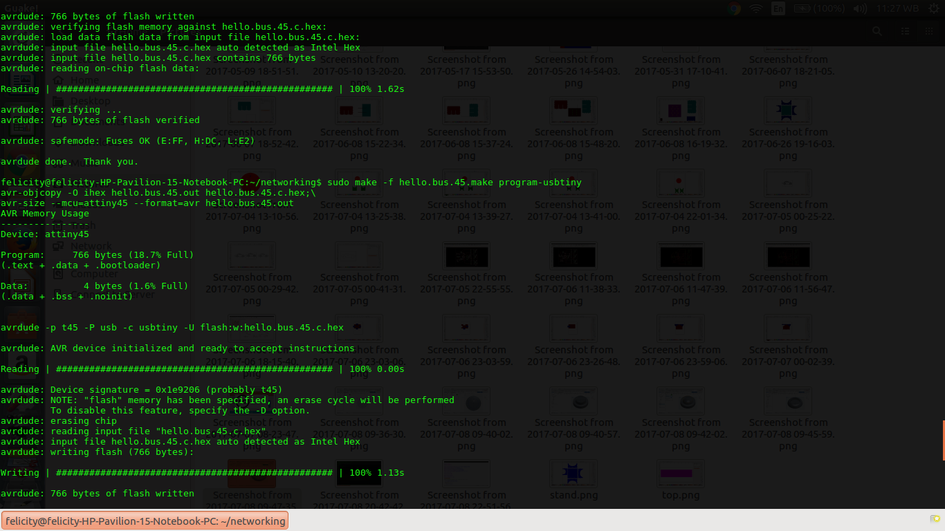
Once i was sure all connections were ok i went on to programming. i started off with downloading the hello.bus.45.c code and the makefile and saving them in the same folder. i then changed into thet directory and wrote the command
sudo make -f hello.bus.45.make
This worked perfectly producing a hex file for uploading
compiling the code
once this was accomplished i ran the following command to upload the code to the bridge. For the bridge i did not modify the code
sudo make -f hello.bus.45.make program-usbtinyThe board was powered via FTDI and hooked up to the fab isp.
connecting the bridge
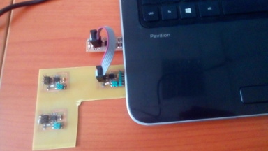
The results were also positive as shown
connecting the bridge
Understanding the code
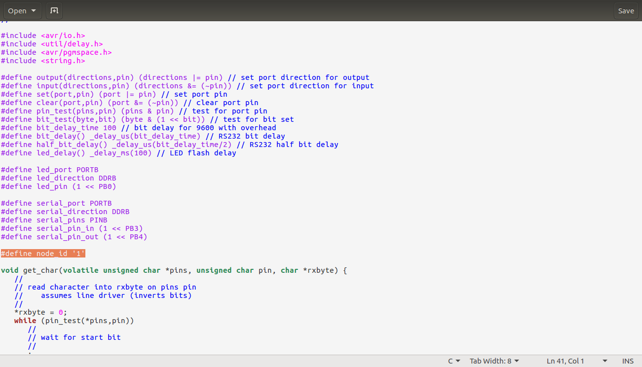
To use the code properly i had to understand the key parameters and what each segment controlled . The following are the key parts and what they control.Node id
The node id is controlled by modifying the following line of code
#define node_id '0'
The receive function
The receiving operation is controlled by the code segment that simulates a read UART operation by bit banging. it first reads the start bit and and then the data bits sequentially one byone with a delay that is equivalent to the baud rate (9600)
void get_char(volatile unsigned char *pins, unsigned char pin, char *rxbyte) {
   //
   // read character into rxbyte on pins pin
   //    assumes line driver (inverts bits)
   //

*rxbyte = 0;
   while (pin_test(*pins,pin))
      //
      // wait for start bit
      //
      ;
   //
   // delay to middle of first data bit
   //
   half_bit_delay();
   bit_delay();
   //
   // unrolled loop to read data bits
   //
   if pin_test(*pins,pin)
      *rxbyte |= (1 << 0);
   else
      *rxbyte |= (0 << 0);
   bit_delay();
   if pin_test(*pins,pin)
      *rxbyte |= (1 << 1);
   else
      *rxbyte |= (0 << 1);
   bit_delay();
   if pin_test(*pins,pin)
      *rxbyte |= (1 << 2);
   else
      *rxbyte |= (0 << 2);
   bit_delay();
   if pin_test(*pins,pin)
      *rxbyte |= (1 << 3);
   else
      *rxbyte |= (0 << 3);
   bit_delay();
   if pin_test(*pins,pin)
      *rxbyte |= (1 << 4);
   else
      *rxbyte |= (0 << 4);
   bit_delay();
   if pin_test(*pins,pin)
      *rxbyte |= (1 << 5);
   else
      *rxbyte |= (0 << 5);
   bit_delay();
   if pin_test(*pins,pin)
      *rxbyte |= (1 << 6);
   else
      *rxbyte |= (0 << 6);
   bit_delay();
   if pin_test(*pins,pin)
      *rxbyte |= (1 << 7);
   else
      *rxbyte |= (0 << 7);
   //
   // wait for stop bit
   //
   bit_delay();
   half_bit_delay();
   }


   //
The transmit function
The transmit code works similar to the receive code. It also sends one character at a time with a delay equivalent to the baud rate
     void put_char(volatile unsigned char *port, unsigned char pin, char txchar) {
   //
   // send character in txchar on port pin
   //    assumes line driver (inverts bits)
   //
   // start bit
   //
   clear(*port,pin);
   bit_delay();
   //
   // unrolled loop to write data bits
   //
   if bit_test(txchar,0)
      set(*port,pin);
   else
      clear(*port,pin);
   bit_delay();
   if bit_test(txchar,1)
      set(*port,pin);
   else
      clear(*port,pin);
   bit_delay();
   if bit_test(txchar,2)
      set(*port,pin);
   else
      clear(*port,pin);
   bit_delay();
   if bit_test(txchar,3)
      set(*port,pin);
   else
      clear(*port,pin);
   bit_delay();
   if bit_test(txchar,4)
      set(*port,pin);
   else
      clear(*port,pin);
   bit_delay();
   if bit_test(txchar,5)
      set(*port,pin);
   else
      clear(*port,pin);
   bit_delay();
   if bit_test(txchar,6)
      set(*port,pin);
   else
      clear(*port,pin);
   bit_delay();
   if bit_test(txchar,7)
      set(*port,pin);
   else
      clear(*port,pin);
   bit_delay();
   //
   // stop bit
   //
   set(*port,pin);
   bit_delay();
   //
   // char delay
   //
   bit_delay();
   }
Sending the character
The data is processed by this function which sends it to the serial port and pin
To program the node i modified the code and changed the node id to 1 as shown
  void put_string(volatile unsigned char *port, unsigned char pin, PGM_P str) {
   //
   // send character in txchar on port pin
   //    assumes line driver (inverts bits)
   //
   static char chr;
   static int index;
   index = 0;
   do {
      chr = pgm_read_byte(&(str[index]));
      put_char(&serial_port, serial_pin_out, chr);
      ++index;
      } while (chr != 0);
   }
Blink function
This is the function that sets the blink operation of the led
  void flash() {
   //
   // LED flash delay
   //
   clear(led_port, led_pin);
   led_delay();
   set(led_port, led_pin);
   }
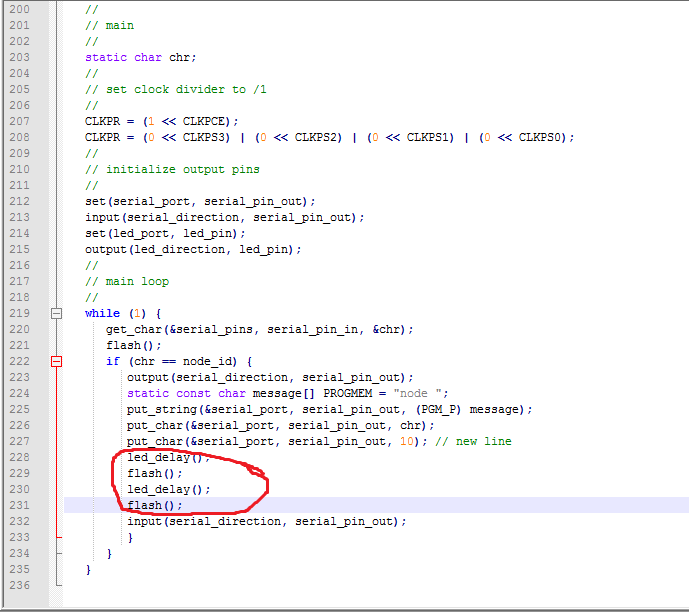
The main loop
This is where all the above functions are called to perform when the buttons are pressed. first the serial ports and directions are set then in the main loop the code checks if the character received is equivalent to the node id and calls the blink function if this condition is true
  int main(void) {
   //
   // main
   //
   static char chr;
   //
   // set clock divider to /1
   //
   CLKPR = (1 << CLKPCE);
   CLKPR = (0 << CLKPS3) | (0 << CLKPS2) | (0 << CLKPS1) | (0 << CLKPS0);
   //
   // initialize output pins
   //
   set(serial_port, serial_pin_out);
   input(serial_direction, serial_pin_out);
   set(led_port, led_pin);
   output(led_direction, led_pin);
   //
   // main loop
   //
   while (1) {
      get_char(&serial_pins, serial_pin_in, &chr);
      flash();
      if (chr == node_id) {
         output(serial_direction, serial_pin_out);
         static const char message[] PROGMEM = "node ";
         put_string(&serial_port, serial_pin_out, (PGM_P) message);
         put_char(&serial_port, serial_pin_out, chr);
         put_char(&serial_port, serial_pin_out, 10); // new line
         led_delay();
         flash();
         led_delay();
         flash();
         input(serial_direction, serial_pin_out);
         }
      }
   }
code
I also modified the ammount of times that the led blinks to two times by adding an extra line of the blink code so that the blinking can be more visible
code modifications
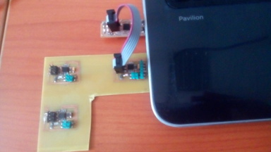
I then powered the nodes using the 4 wire bus as shown and hooked it up to the programmer. i ran the same command as before sudo make -f hello.bus.45.make program-usbtiny
connecting the node
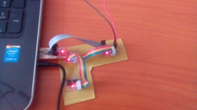
The final result was as shown