This week's assignment was to design and make a board and include at least one output device and program it.
I chose to do charlieplexing with an attiny 45 and six leds.
BOM
component
quantity
Attiny 45
1
red leds
6
resistor 100 ohms
3
isp header
1
power header
1
jumper wire
1
Designing the board
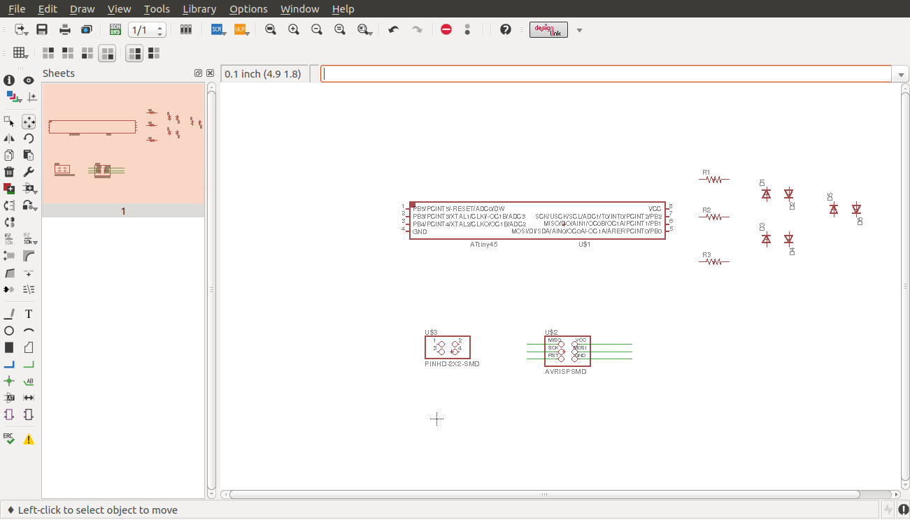
I designed the board first using eagle. i started by placing my components on the schematic
I then connected the wires and nets to the respective pins
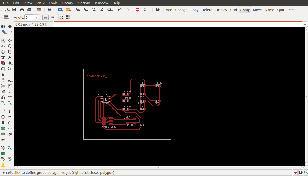
placing
routing
outcome
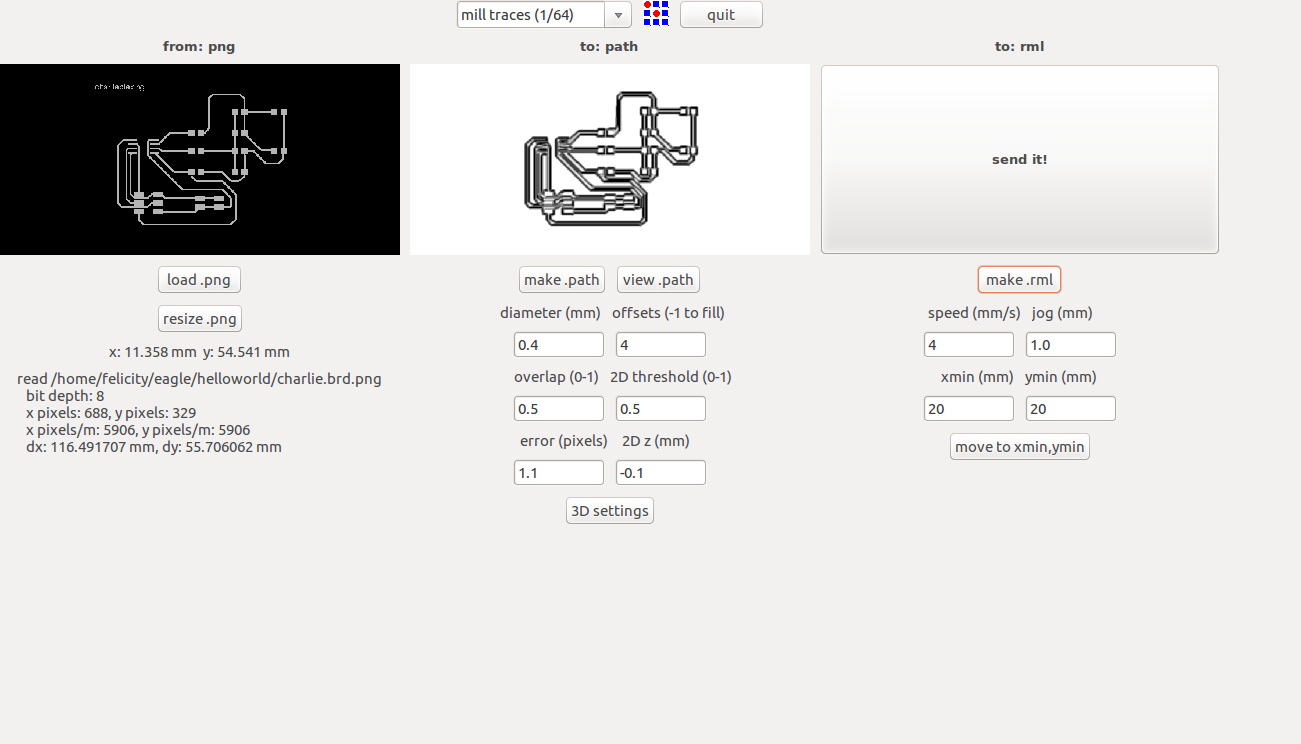
fab modules
below shows my fab modules settings for making the board
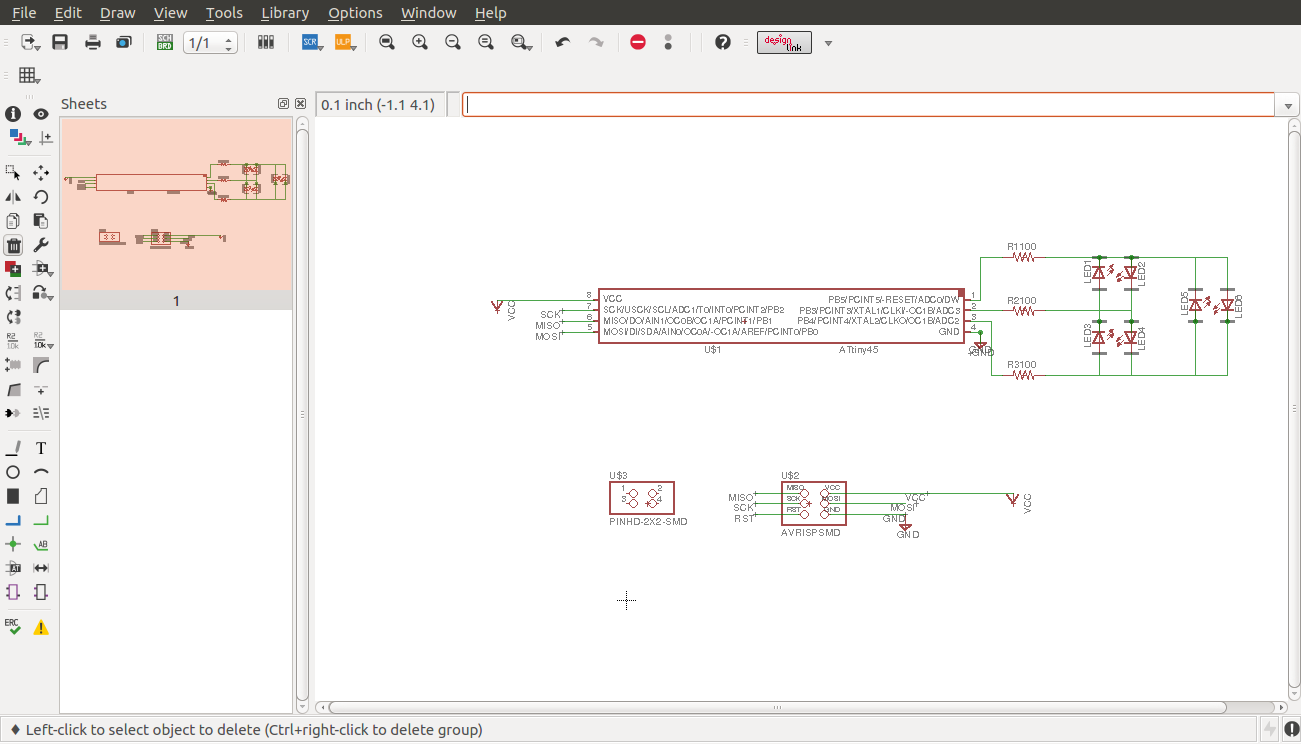
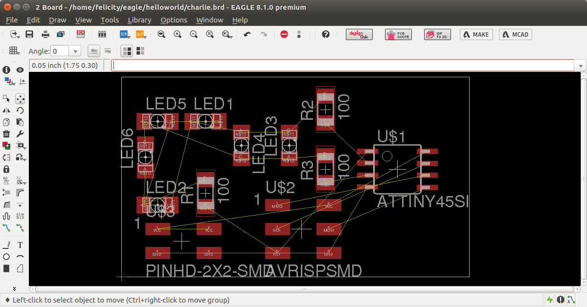
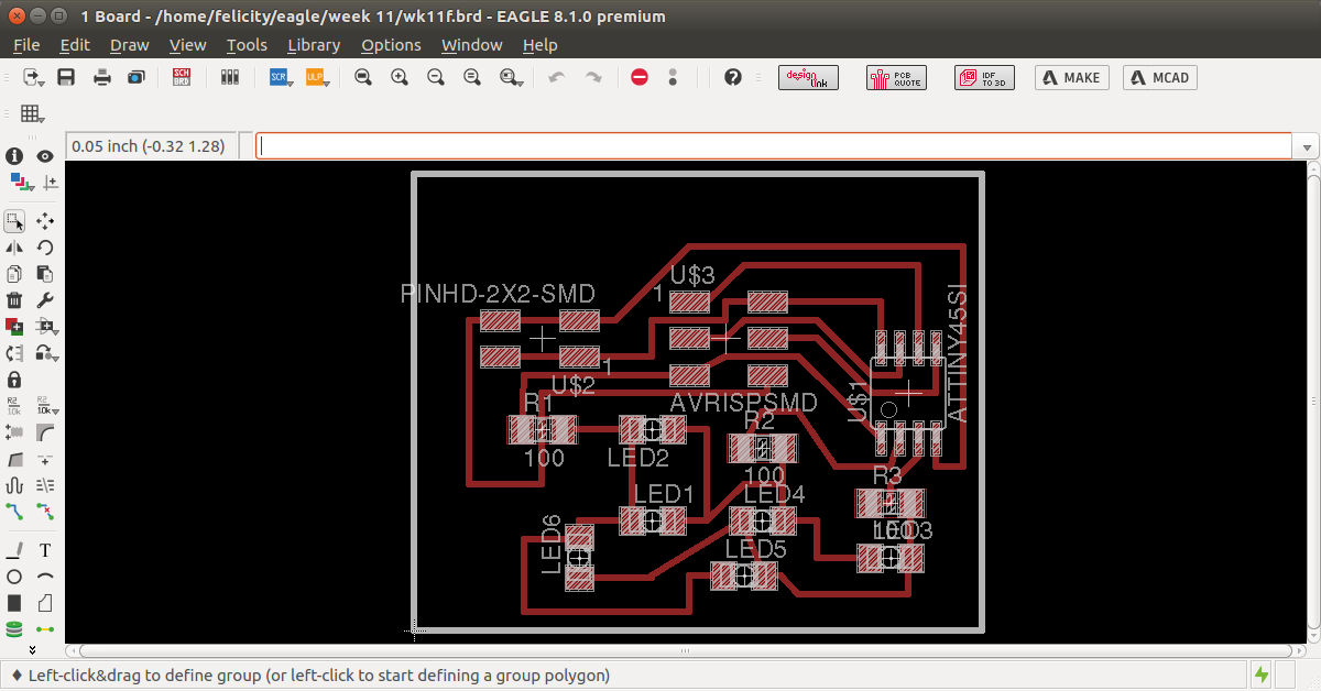
This board turned out to be too big so i set off to redesign it and make it smaller and compact
Redesigning the board
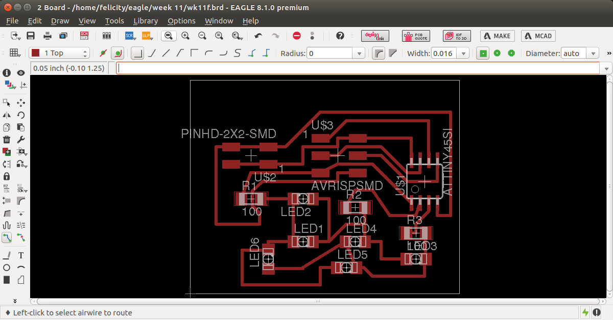
I set off to redesign the board and change the size of the board
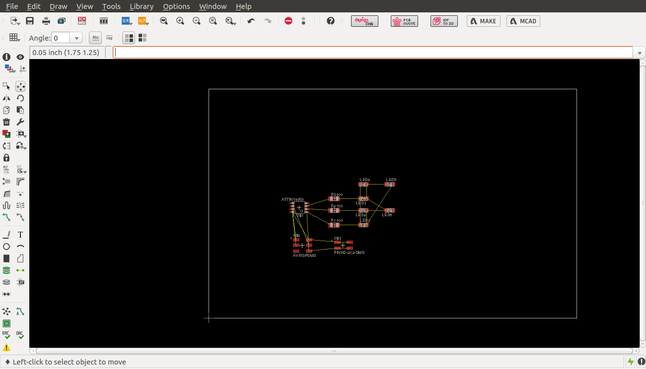
placing the components
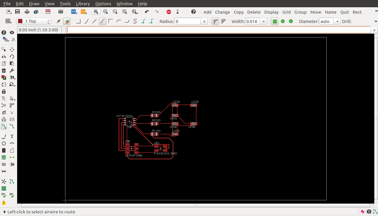
routing
final outcome
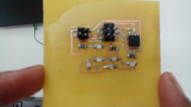
fabbed and stuffed board
Programming
To program the board i connected it to my fab isp programmer used the following command on command prompt
defines the function for putting the first led on. The line DDRB=0b00101000; sets pin 3 and 5 in portB as outputs.
The line PORTB=0b00100000 sets pin 5 of portB high hence putting on Led 1. In the main loop while 1() we call the different functions to turn on the desired led with a delay of 1 second.
Problems encountered and solutions
The board at first on programming issued no output . on checking the datasheet i realised one of the output pins used (pin 1) is the reset pin. I had to use the command rstdsbl command to turn the reset pin to an i/o pin. Even after getting output the leds did not blink in the desired sequence. i had to change their orientation several times.