Networking and Communications
Short note before starting:
For this assignment I planned to communicate my Button+LED board from the Electronics Design assignment with my microcontroller board from the Output Devices assignment.
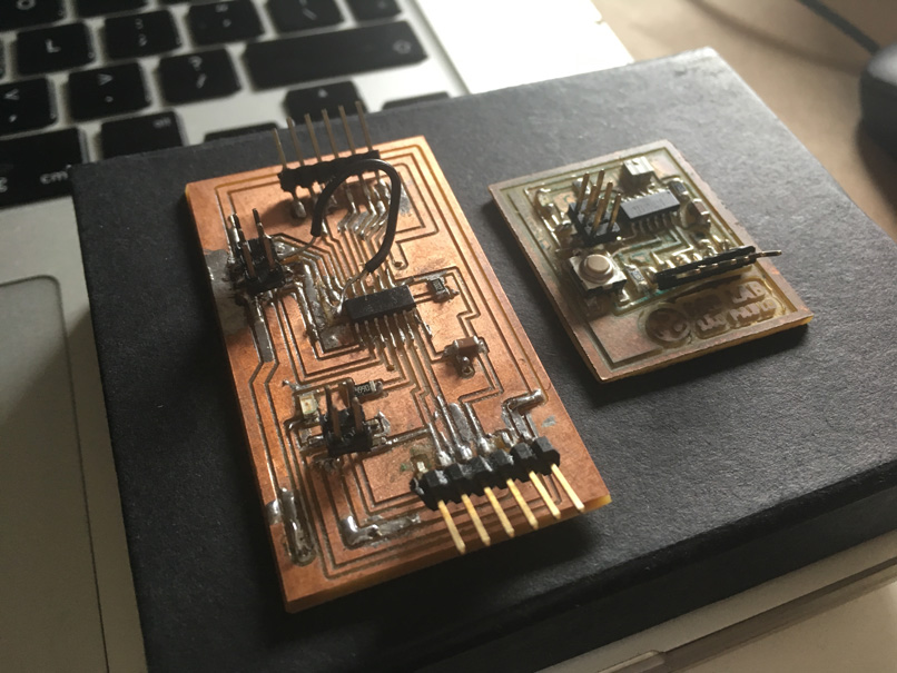
Both boards have a ATtiny 44 microcontroller installed and the intention is to establish a wired network between both.
Before starting I did a research to check if somebody else had the same idea like me to connect two different boards and communicate both by pressing a button as a request and having a LED flashed as a response.
I found the page of May El-Dardiry that documented a similar communication and helped a lot as a departure point!
Like him, the connection I established between my two boards is a “Serial Communication”.
I copied the code to the Arduino IDE and it appeared an error “Serial was not declared in this scope”. I remembered that I had a similar problem when writing the code for my Input Device and the solution was to learn with the “Software Serial Example” from Arduino examples.
So what I did was to add the lines “#include
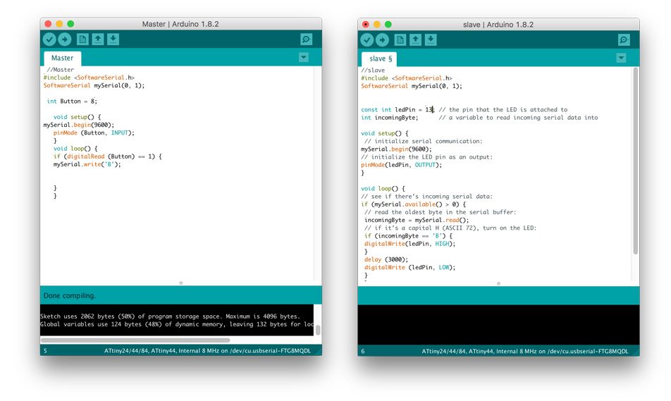
But there was an important thing that I had to change before uploading the code to the boards. I had to change the reference numbers for the pushbutton and LED ports according to the schematic of my boards. To do that I had to check the ATtiny/Arduino diagram to find the correspondent Arduino port to my ATtiny 44 pins. I also checked the number of the pins for RX, TX that appear just after declaring SoftwareSerial “mySerial(0, 1)”, both numbers were correct. After the changes my code looked like this:
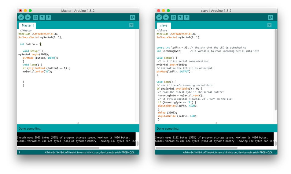
Now that both codes were compiled successfully I started uploading them to the respective boards. First I plugged my FabTinyISP to the master board, that is the board with the button. The upload was done correctly!
Next I uploaded the slave code into the microcontroller board that has a built in LED. It also uploaded fine!
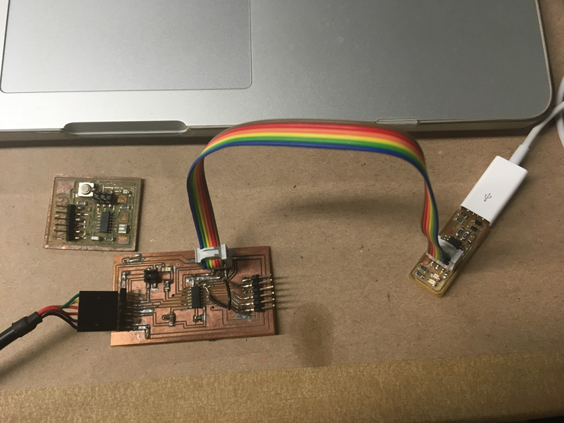
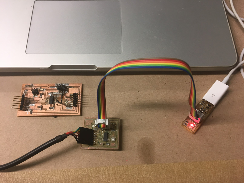
Finally I unpluged the FabTinyISP from the slave board and powered, with the FTDI, the master letting it connected to the slave board via the networking pins.
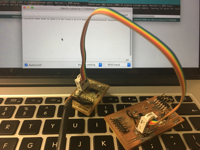
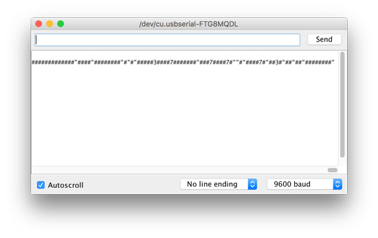
When I opened the serial monitor of the master board I noticed that something was happening, some characters that did not make any sense continuously appeared in the monitor and would only stop when I pressed the button. The LED in the microcontroller board didn’t flash as I expected but judging by the information in serial monitor I believe that somehow some communication was established between both boards.
After a research I noticed that several people had the same issue trying to communicate ATtiny 44 and maybe that’s why most of the examples that went right were done using ATtiny 45 instead.
I’ll continue trying to debug my code in order to refine the communication I believe that I achieved. If I don’t succeed, even with the help of my tutor I plan to design a new board using a ATtiny 45.
Experimenting with I2C protocol
In order to have the experience of working with I2C communication I chose to do an experiment trying to communicate two Arduinos with each other in a Master Reader/Slave Sender organisation via I2C synchronous serial protocol that is used to attach lower-speed peripheral integrated circuits to processors and microcontrollers in short distance.
For that I used the Arduino Wire Library and followed the tutorial at Arduino official page.
I used 2 Arduino’s to establish the communication, being one the “Master” that was programmed to request and read information sent by the second Arduino named “Slave”.
To send the information the I2C protocol uses the SCL (serial clock pin) that the Master will pulse at regular intervals and a SDA (serial data pin) that is over which the data is sent between both.
“As the clock line changes from low to high (known as the rising edge of the clock pulse), a single bit of information - that will form in sequence the address of a specific device and a a command or data - is transferred from the board to the I2C device over the SDA line. When this information is sent - bit after bit -, the called upon device executes the request and transmits it's data back - if required - to the board over the same line using the clock signal still generated by the Master on SCL as timing."
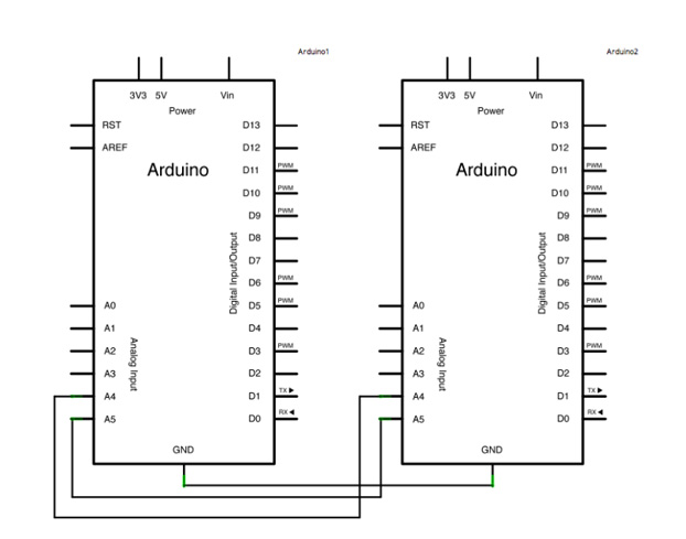
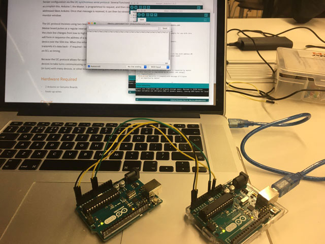
The circuit is very simple, I just had to connect the grounds,the pins 4 (SDA) and the pins 5 (SCL) of the two arduinos with hook-up wires and also another wire to transfer 5V from the master board to the VIN pin of the slave following this schematic:
I uploaded the code for master and the code for the slave separately once they differ from each other, both has an unique address because of the I2C protocol.
Master:
#include
void setup() {
Wire.begin(); // join i2c bus (address optional for master)
Serial.begin(9600); // start serial for output
}
void loop() {
Wire.requestFrom(8, 6); // request 6 bytes from slave device #8
while (Wire.available()) { // slave may send less than requested
char c = Wire.read(); // receive a byte as character
Serial.print(c); // print the character
}
delay(500);
}
Slave:
include
void setup() {
Wire.begin(8); // join i2c bus with address #8
Wire.onRequest(requestEvent); // register event
}
void loop() {
delay(100);
}
// function that executes whenever data is requested by master
// this function is registered as an event, see setup()
void requestEvent() {
Wire.write("hello "); // respond with message of 6 bytes
// as expected by master
}
I connected the master to the USB and the slave responded to the master request of sending 6 bytes of information, that in this case it was the word “hello”. The code worked fine since I was able to check the bytes received from the master in the serial monitor of the Arduino IDE.
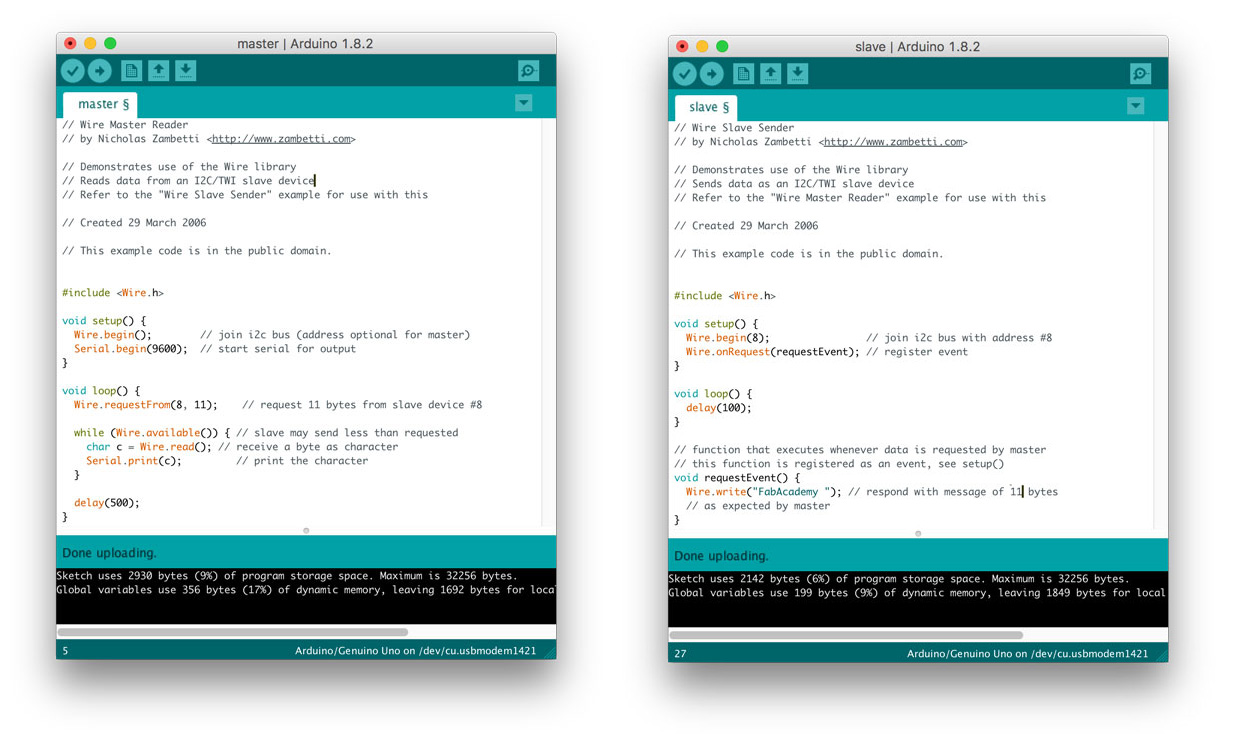
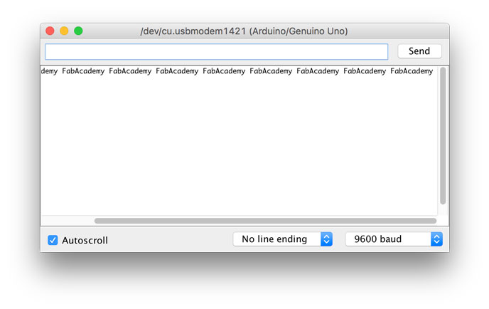
I tried changing the word “hello” to “FabAcademy” but it didn’t appeared complete in the serial monitor. I found that the reason for that is that the number of bytes requested by the master is directed linked to the number of characters of the message being sent. Having that in mind I changed the word to “FabAcademy “ (with a additional space at the end) which gives me 11 bytes and changed the lines in both codes accordingly. The result is that I managed to establish the communication with the exact number of characters that I envisioned!
Softwares used:
- Arduino IDE
Files: