Input Devices
Short note before starting:
For this assignment I’ll keep the experience of measuring light with a sensor, an assignment that I completed in 2013, but I’ll add an experiment where I measure proximity with a microcontroller board that I designed now in 2017.
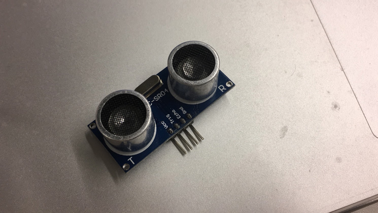
Understanding the Ultrasonic Sensor
Because this was the first time I worked with an ultrasonic sensor, I did a research to understand how it works. This device measures the distance to any object by calculating the elapsed time between sending and receiving back sound waves.
According to the Ultrasonic Sensor HC-SR04 DataSheet the device provides 2cm to 400cm non-contact measurement function.
It has 4 pins being VCC for current supply, Trig for INPUT, Echo for OUTPUT and GND for ground.
Controlling the Ultrasonic Sensor - First try
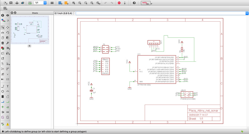
When I first attempted to work with the ultrasonic sensor I designed a single board with a microcontroller to communicate with the sensor and send back the information to the computer.
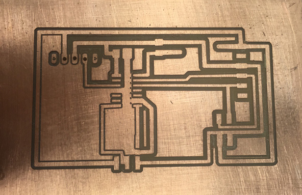
The design of the board, made in Eagle basically, has a ATtiny 44, the 6 pin head for programming the microcontroller, a 4 pin head for network, the 6pin for FTDI connection and the sensor connected to the pin PB1 (3), the VCC and GND.
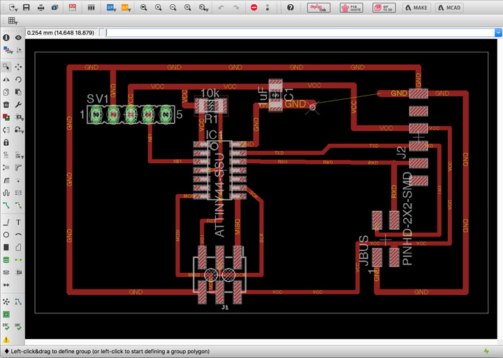
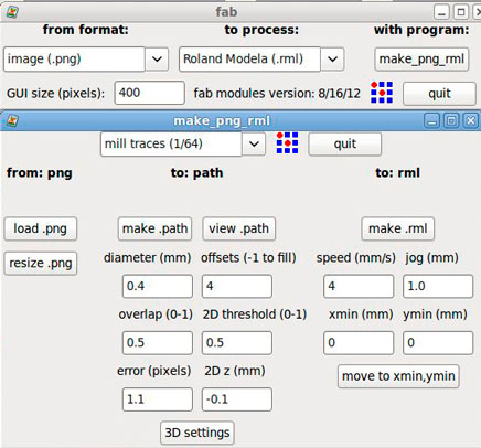
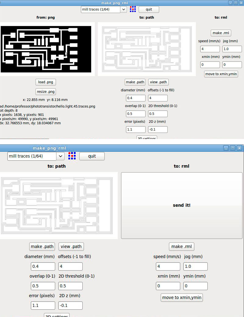
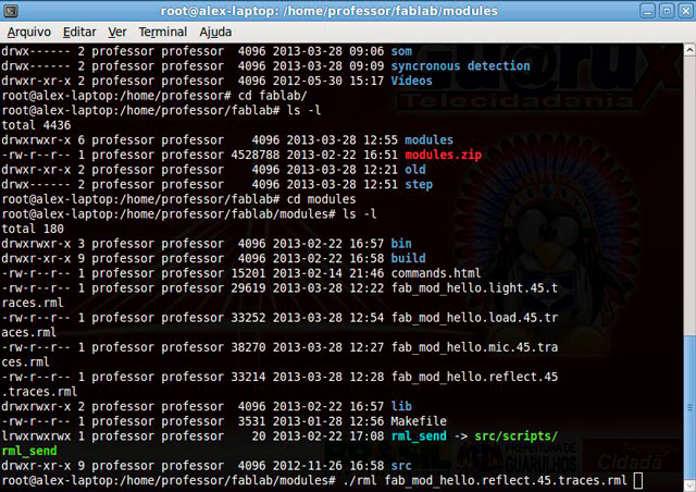
After I finished designing the circuit it was time to export it as a .PNG file and open it in FabModules in order to generate the .RML files. Until here everything was fine!
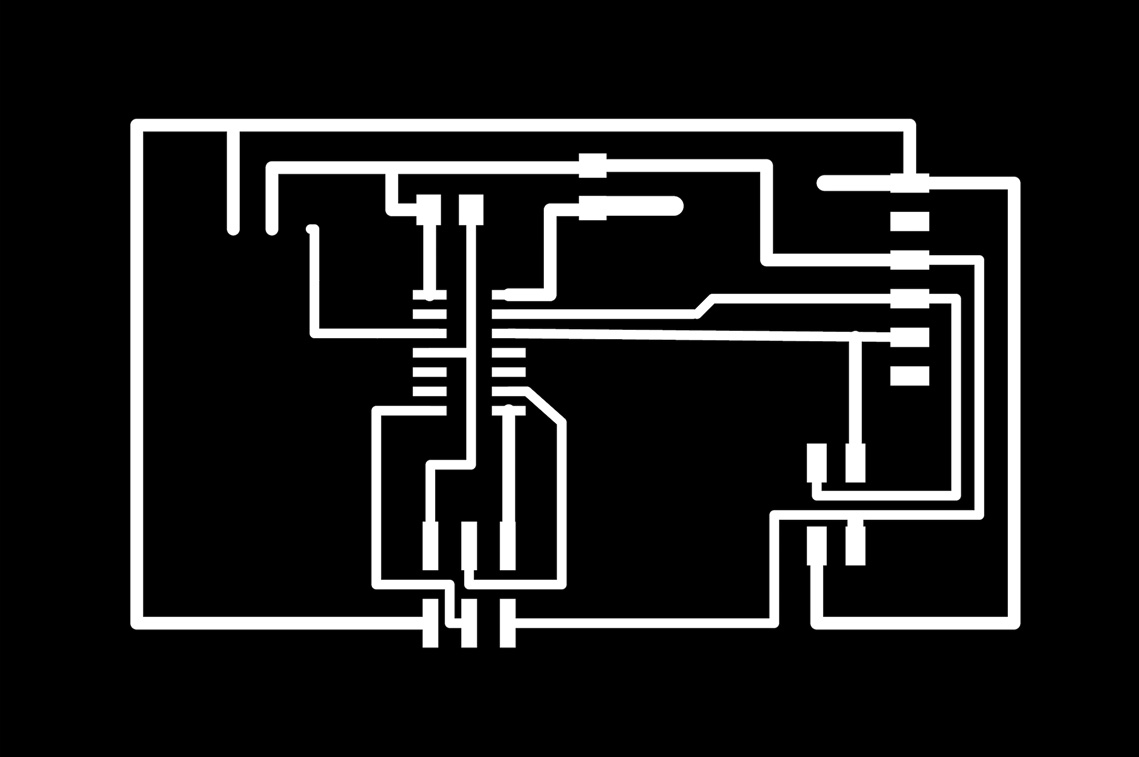
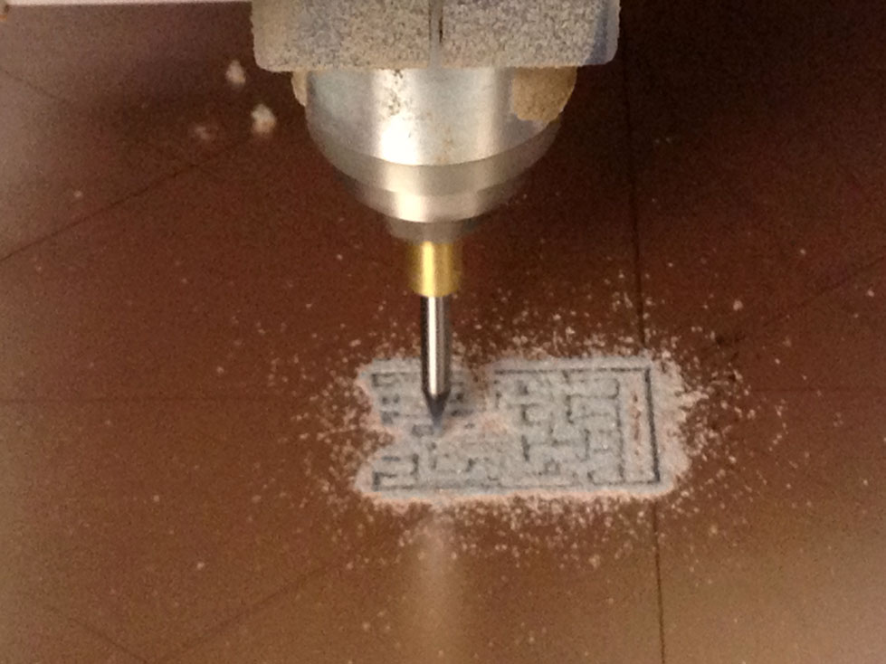
When it came the time for milling it, something wrong happened that the traces were not entirely milled. I just noticed it the next day when I was performing a continuity test with a multimeter that some traces were ignored by the mill. My guess is that the bit was broken during the milling since the .PNG and .RML were ok.
After noticing the problem I decided to try again, with the resources I had in hand to control the ultrasonic sensor. This means using the ports of the microcontroller board that I designed to control the sensor (this experiment will be described below). It’s important to say that I intend to mill my ultrasonic sensor board again (with a brand new bit) in order to document it in here.
Controlling the Ultrasonic Sensor - Second try
To control my ultrasonic sensor I decided to use the microcontroller board that I created in the assignment 10.
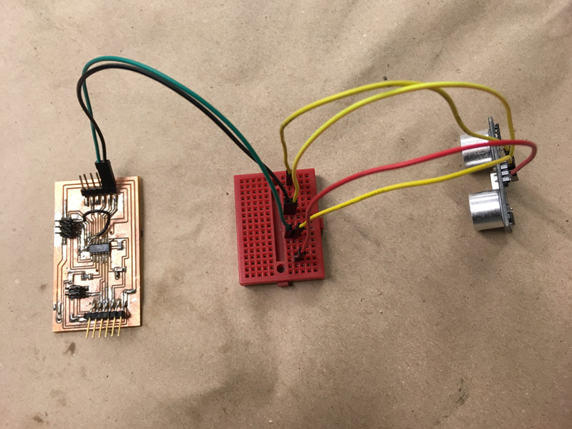
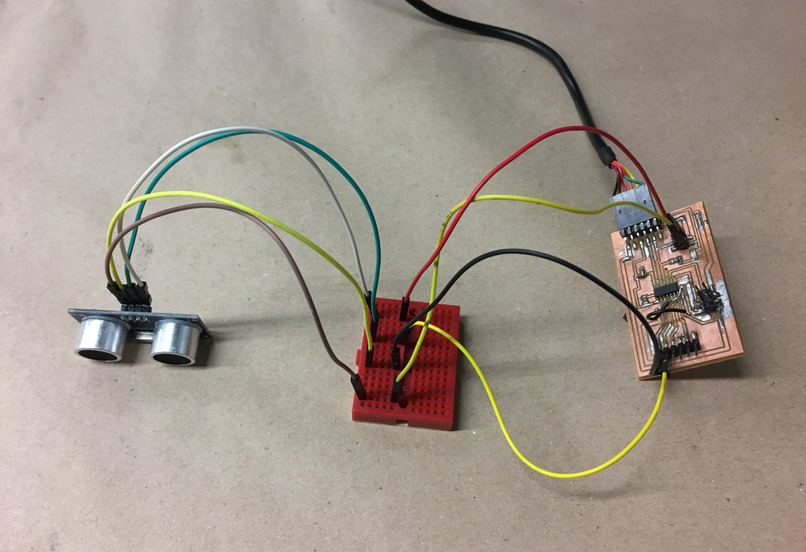
My microcontroller (ATtiny 44) has 5 pins that could be used that are: PB0, PB1, PB2, PA7, PA3. In order to connect my microcontroller to read the input from the ultrasonic sensor I had to chose any 2 pins, one for connecting to the Input(trig) and another to connect to the Output(echo). I decided to establish this connection using PB0 (pin 2) for output and PB1 (pin 3) for input. The ground and the VCC pin of the sensor I connected at the communication pins of my microcontroller board.
I used a breadboard to extend the wires a little longer and the connection looks like this:
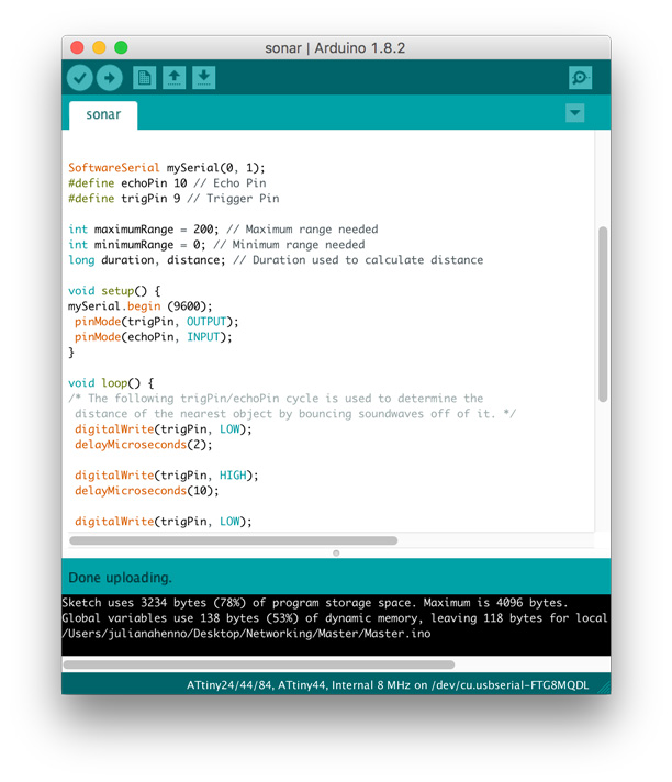
To program the microcontroller board I followed the steps from this tutorial that dealed with the same issue of programming a microcontroller to read the input of a ultrasonic sensor. The code is the following:
/*
HC-SR04 Ping distance sensor:
VCC to arduino 5v
GND to arduino GND
Echo to Arduino pin 7
Trig to Arduino pin 8
This sketch originates from Virtualmix: http://goo.gl/kJ8Gl
Has been modified by Winkle ink here: http://winkleink.blogspot.com.au/2012/05/arduino-hc-sr04-ultrasonic-distance.html
And modified further by ScottC here: http://arduinobasics.blogspot.com.au/2012/11/arduinobasics-hc-sr04-ultrasonic-sensor.html
on 10 Nov 2012.
*/
#define echoPin 7 // Echo Pin
#define trigPin 8 // Trigger Pin
#define LEDPin 13 // Onboard LED
int maximumRange = 200; // Maximum range needed
int minimumRange = 0; // Minimum range needed
long duration, distance; // Duration used to calculate distance
void setup() {
Serial.begin (9600);
pinMode(trigPin, OUTPUT);
pinMode(echoPin, INPUT);
pinMode(LEDPin, OUTPUT); // Use LED indicator (if required)
}
void loop() {
/* The following trigPin/echoPin cycle is used to determine the
distance of the nearest object by bouncing soundwaves off of it. */
digitalWrite(trigPin, LOW);
delayMicroseconds(2);
digitalWrite(trigPin, HIGH);
delayMicroseconds(10);
digitalWrite(trigPin, LOW);
duration = pulseIn(echoPin, HIGH);
//Calculate the distance (in cm) based on the speed of sound.
distance = duration/58.2;
if (distance >= maximumRange || distance <= minimumRange){
/* Send a negative number to computer and Turn LED ON
to indicate "out of range" */
Serial.println("-1");
digitalWrite(LEDPin, HIGH);
}
else {
/* Send the distance to the computer using Serial protocol, and
turn LED OFF to indicate successful reading. */
Serial.println(distance);
digitalWrite(LEDPin, LOW);
}
//Delay 50ms before next reading.
delay(50);
}
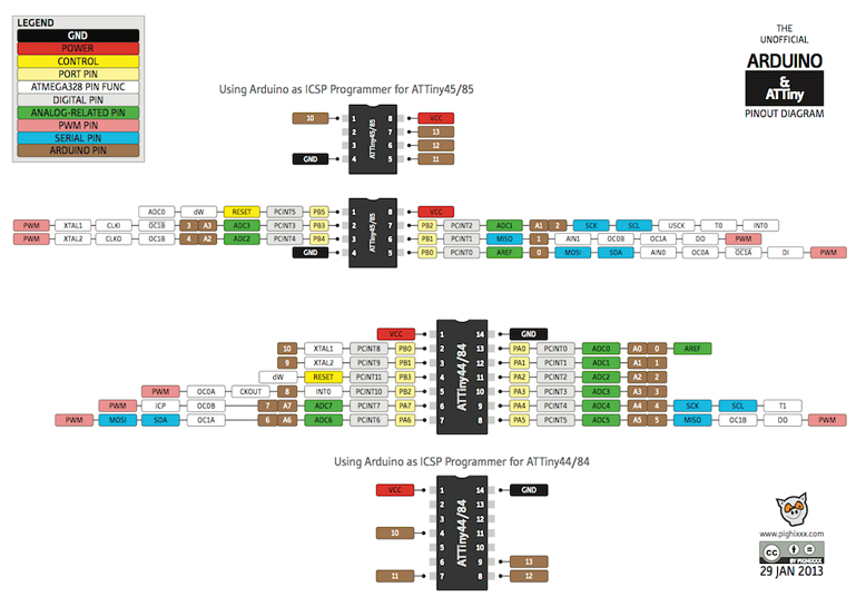
First thing I did before running the code was to change the ports related to Echo and Trig to the correct ones. For doing that I had to check the ATtiny/Arduino diagram (displayed above) and search for the correspondent Arduino pins to the ATtiny pins 2 (PB0) and 3 (PB1) and I found out that I should use pin 10 for output and 9 for input.
I also eliminated the lines of the code mentioning the LED (the LED pin that the code refers is the Arduino onboard pin that comes with it). Another important thing is to define the Arduino tool setting as “board” (ATtiny 44), “processor” (ATtiny 44), “clock” (Internal 8MHz), “port” (.usbserial) and “programmer” (USBtinyISP).
After everything was set and the USBtinyISP was correctly plugged to my microcontroller board, I burned the bootloader and noticed that I was having some issues regarding the “Serial”. My tutor Kenzo Abiko helped me while showing me the SoftwareSerial Example from Arduino IDE. I learned that this SoftwareSerial library allow a serial test to be runned, receiving from a hardware serial and sending to the software serial and the other way around receiving from the software serial and sending to the hardware serial.
To adjust the code to this software serial example I had to add one line including SoftwareSerial library and change all the “Serial.” to “mySerial.”. After performing those changes, the code was uploaded without any problem.
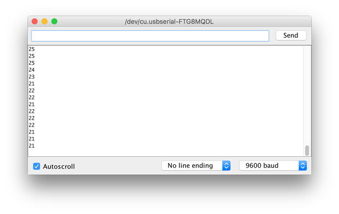
After disconnecting my in-circuit programmer “USBtinyISP” from the microcontroller board I tested the ultrasonic sensor by checking what was going on in the Serial Monitor. The sensor was working fine and the monitor displayed varied numbers according to the measurements from the proximity that were being inputted.
Ultrasonic sensor from Juliana Henno on Vimeo.
Measuring light - Past experience during FabAcademy 2013
This week´s assignment was to add a sensor to a microcontroller board and measure the results. Because of my past surveys on the theme colour as a light source, I decided to measure light.
Since the last assignments the electronic theme has been increasingly less scary for me. I´m getting along with this environment and this is helping me to face the new assignments that seem to be getting each time more complex.
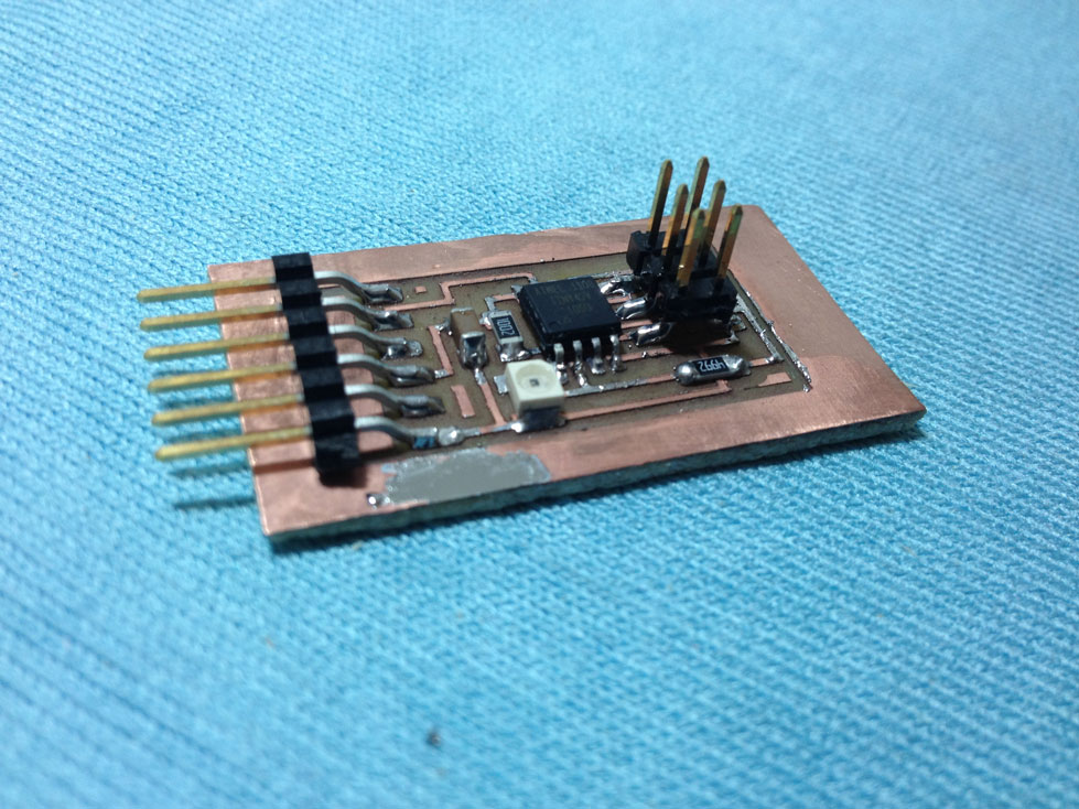
After defining the kind of sensor I wanted to work with, I saved all the files regarding the “phototransistor” light sensor that was listed under the assignment official page schedule.
The first step was to mill the board, and for this task I just had to open the traces/interior file in the Fab Modules and send it to print through a command in the terminal to the Modela MDX-40A. We still are having problems setting the X, Y and Z axis from the Fab Modules, because of this we are setting the axis in the Modela software and completing the “send to print” process in the Fab Modules.
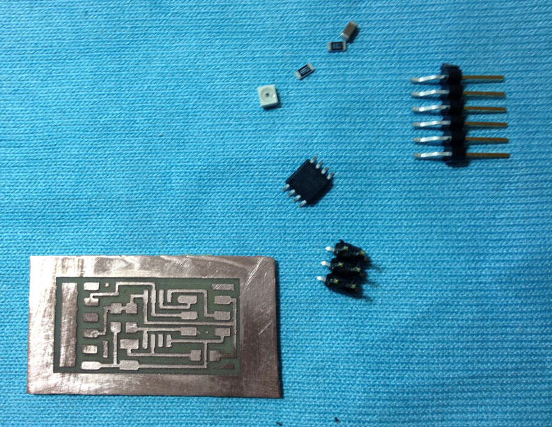
Just in case I milled two phototransistor boards in case it would be necessary in the programming process.
After the boards were printed I started sorting the components. Now it´s getting easier to find the components and this step was completed really fast! I used the “board” page as a reference to find the components.
Once the components were separated I soldered them, always taking as a reference the “board” scheme. The soldering was easier than in the last time and I started refining the techniques I learnt in order to obtain a better looking joints in the board. It didn't take me a lot of time to accomplish it.
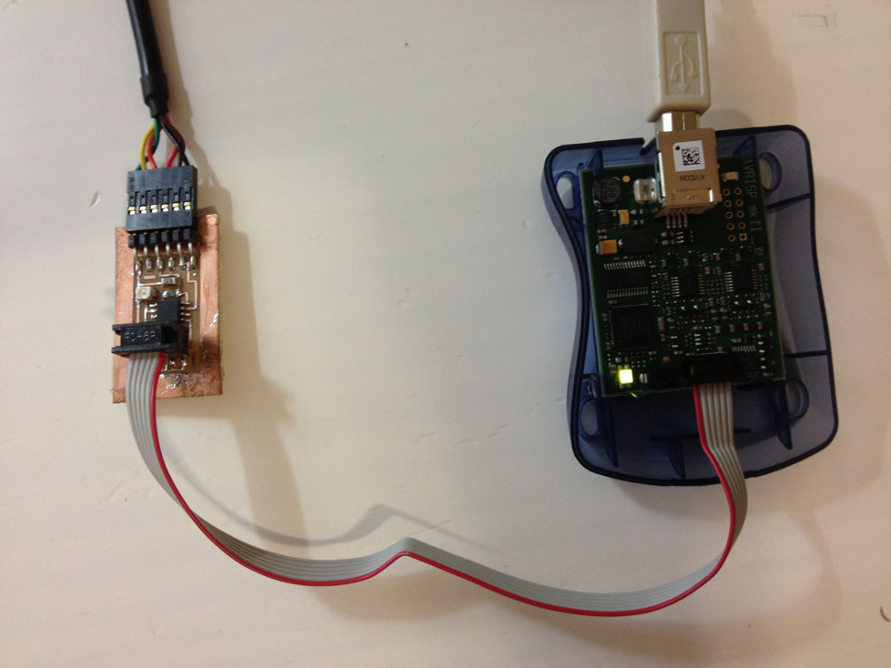
After my board was soldered I started to program it. The first thing was to connect the phototransistor board to the programmer (AVRISPmk2). My FabISP was not working correctly, so I decided to use the AVRISPmk2 for this assignment. After plugging the phototransistor to a FTDI cable (to power the board) and to the programmer (through a ISP cable) the LED of AVRISPmk2 went green, that was a good sign!
The programming is still a huge task for me to solve. I tried programming the board in Windows 7 (64bit) through the Cygwin Terminal but it didn´t work. I tried programming with the Arduino software and it didn´t work either. I also followed the steps on the Providence tutorial and I had no luck. The part of “try to program” took a lot of time and I could not accomplish it before the deadline. It´s too early to say that the problem was with the components position on the board, because the programs I run were not working normally (as I noticed while following the tutorials). I intend to continue with this assignment during the next week in order to keep track on the next electronic-related assignments.
Further progress on assignment #10
After accomplishing the first steps of this assignment, which was printing and soldering the components I stopped at the programming phase due to some difficulties I found. I had some trouble downloading the Cygwin terminal and luckily I managed to install it correctly!
What I installed: Cygwin, Mercurial and Winavr
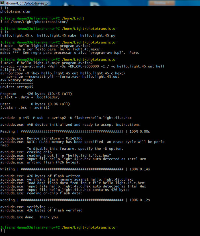
After installing Cygwin I entered the following command in order to program the board through the ATAVRISP2 programmer:
Juliana Henno@JulianaHenno-PC /home/Light/phototransistor
$ make -f hello.light.45.make program-avrisp2
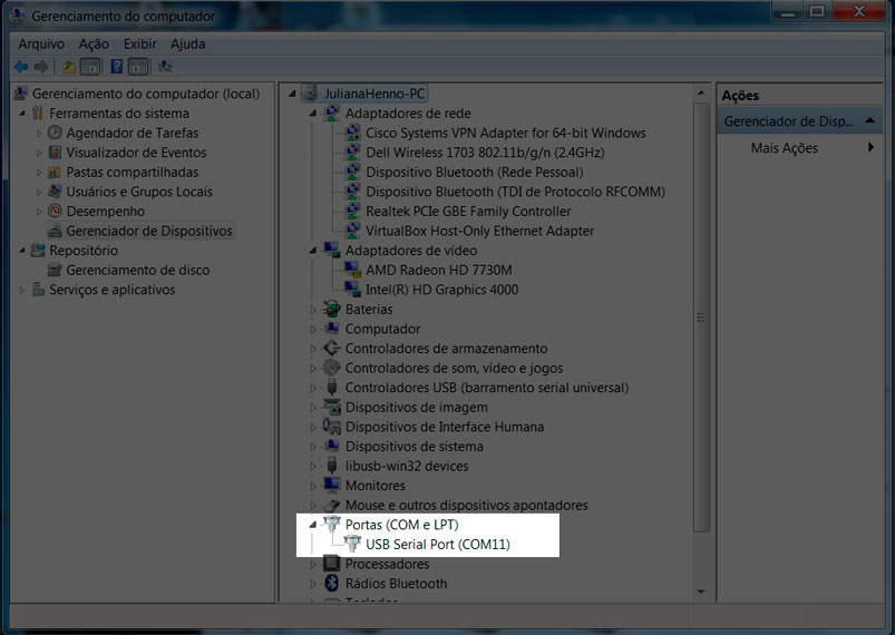
After the board was programmed the next step was to run the Python file (hello.light.45.py) in order to visualize the board working. To do so I had to discover in what USB port my board was connected. As my phototransistor board was plugged to a FTDI cable I noticed my board was connected to the port 11. So I tried to run the Python program.
In Cygwin I tried entering the following command:
Juliana Henno@JulianaHenno-PC /home/Light/phototransistor
$ python hello.light.45.py /dev/com11
Traceback (most recent call last):
File "hello.light.45.py", line 67, in < module>
root = Tk()
File "/usr/lib/python2.7/lib-tk/Tkinter.py", line 1685, in __init__
self.tk = _tkinter.create(screenName, baseName, className, interactive, wantobjects, useTk, sync, use)
_tkinter.TclError: no display name and no $DISPLAY environment variable
But it didn´t work and I got this error notice.
I tried once again to run Python to visualize my sensor board using Cygwin and it worked. For me it was great to see how far I have reached in the electronics field! I almost gave up on the way but thanks to my fabber colleagues and all the people that are kindly helping us in the Lab I managed to accomplish one more electronic related task!
Until now I was working with the phototransistor board but there was an accident during the manipulation of the board and I could not use it anymore. So I used my second option board: a “synchronous detection spread spectrum” that worked detecting the reflection of a LED light upon the sensor. Because I changed the board I had to do all the initial steps of this assignment all over again.
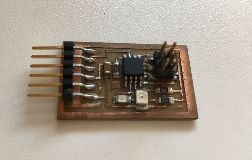
I first tested the board using AVR (AVRISP2), I connected the board to a FTDI cable and to the programmer (ISP cable) and noticed that the board was well soldered (the green light was glowing). Nice start! With the board connected to the programmer and to the computer I entered into the programming phase. For it I had to download the C file, the make file and the Python file and save them inside the Cygwin folder (C:>Cygwin>home>Light>reflect). The next step was to program the board and for it I used the Cygwin terminal. I typed the following command in order to program my board:
Make –f hello.reflect.45.make program-avrisp2
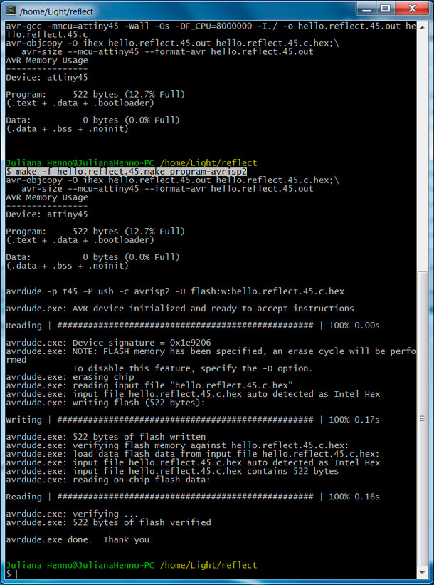
The command was successful to program the Attiny45 microcontroller I had in the board!
Next I identified the port the board was connected to in my computer. I found out that it was port 11. This information will be needed when I run the Python through the terminal.
But until now there was no mystery, I managed to reach to this point using the former board but I was up against a huge task: running Python through Cygwin. The tutorials we found in the internet did not explain how we could run Python from Cygwin because everybody who tried the same experiment had used Ubuntu or Mac as a platform. In our case, in the FabLab SP, we could only use PC, so we had to search in forums how to run Python from Cygwin having a Windows 7 (64bits). The research went well and the fabber Alex Garcia found a site that explained the correct command to run the Python through Cygwin:
Cygstart /cygdrive/c/cygwin/home/Light/reflect/hello.reflect.45.py com11
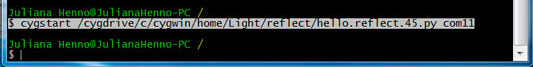
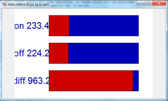
It worked perfectly! And the window with the graphics showing the result of the sensor appeared in the screen:
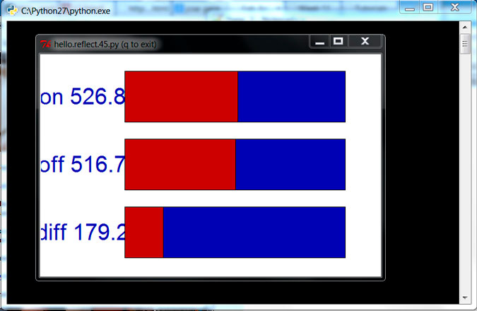
After succeeding using Cygwin we decided to run Python through the Windows terminal (CMD). The command, that everybody was using in the tutorials to run Python in Windows worked here perfectly! After opening CMD I entered the following command:
Python hello.reflect.45.py com11
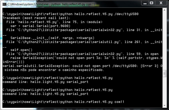
And after that it appeared the graphic window displaying the results of the sensors!
Softwares used:
- Fab Modules
- Cygwin Terminal
- Arduino software
- Python
Machines used:
- Modela MDX-40A
Files: