- Week 14 +
composites
Tasks
Coupon
Material Exploration
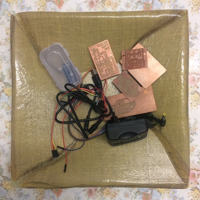
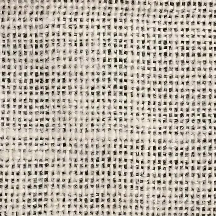
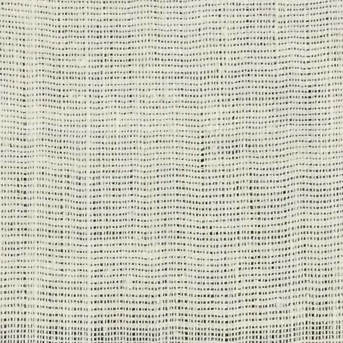
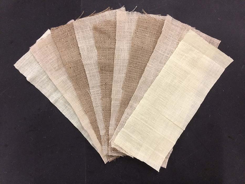
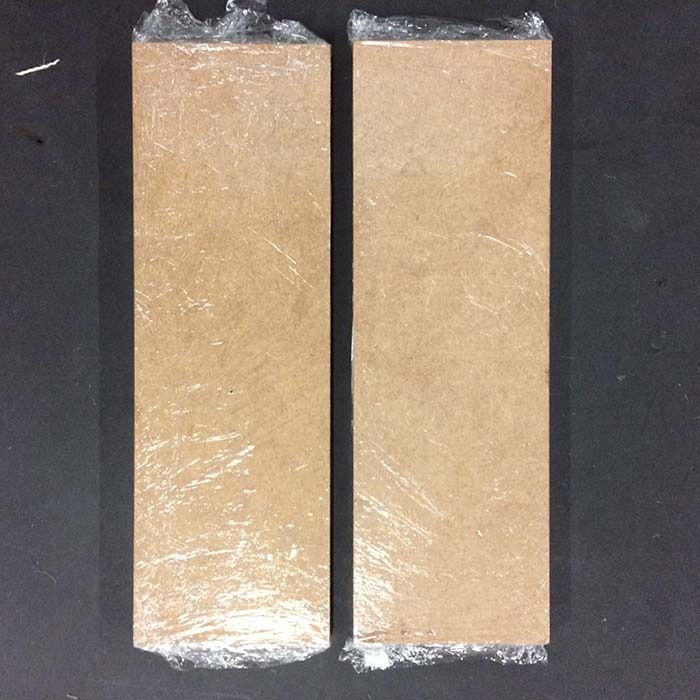
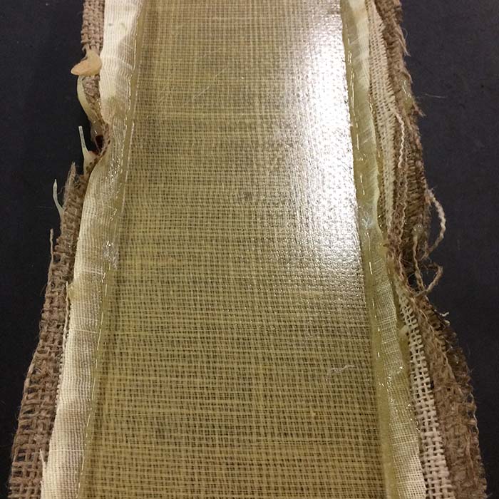
Before initiating design process, I decided to make a -test coupon- to check strength and limitations of composite, and also various possibilities it could offer. Since, composite should have a materials that could take compressive as well as tensile foreces, I choose to go for natural fibre and in resin matrix. So, I procured burlap of two kinds, one with thinner fibre and other slightly thicker. Observing their permeable nature, I thought of combining them with khadi fabric which is comparatively less pervious than both types.


Layering, Infusion and Compaction
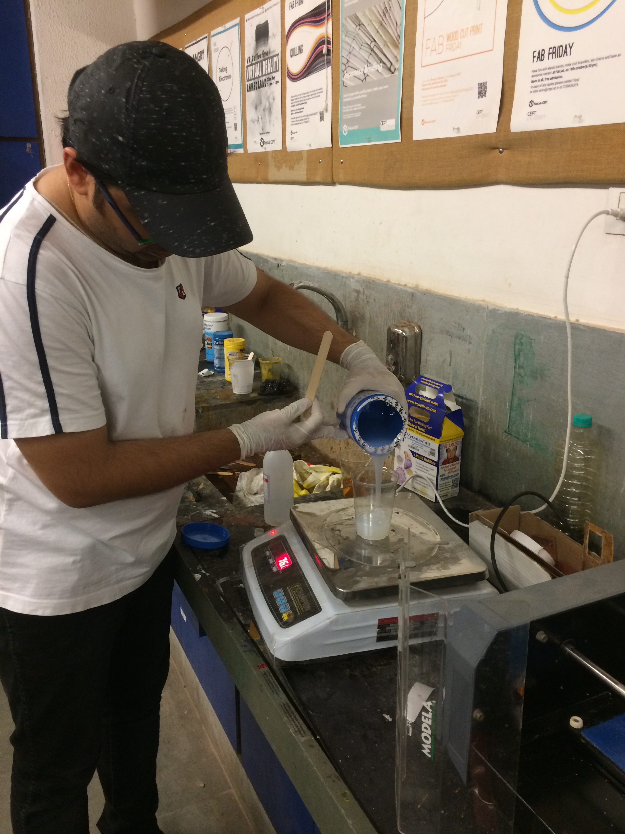
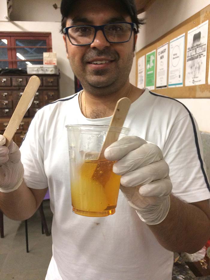
To make the coupon, I took 25cm x 10cm rectangular pieces of all three types and layered them alternatively one over the other. The coupon I am making has nine layers of fabric in epoxy resin matrix. The reaction ratio of epoxy resin to hardner is 100:80 by weight.

Then I quickly applied resin with the help of wooden tongue depressor, one by one, as the shelf life of the mix is nearly half an hour. As even contact throughout suffices to ensure proper cure, I clamped it tightly and kept it aside for 10 hours in order to achieve handling strength as mentioned in the data-sheet.


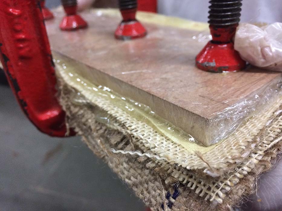
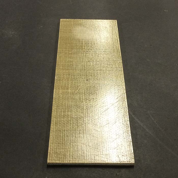
Lesson Learned
I should have applied lesser quantity of resin in the composite. To ensure the composite is evenly infused with resin, I applied too much of resin, casuing excessive resin to overflow from its sides.
Mold design and construction
3D Designing
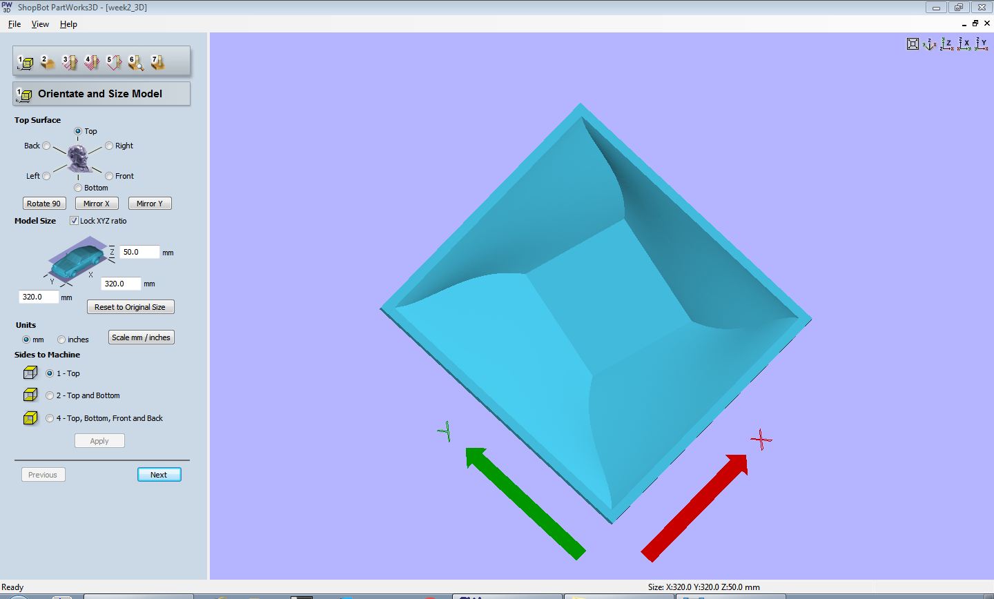
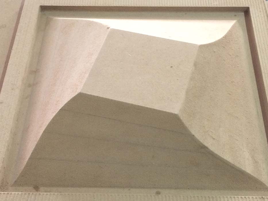
For this exercise, I am using my week 2 - 3D design created in Rhino. It is 320mm x 320mm in size and is something I wish to make composite of. It seems a challenging task to me and not really sure if I am going to succeed or not. But I am still giving it a try.
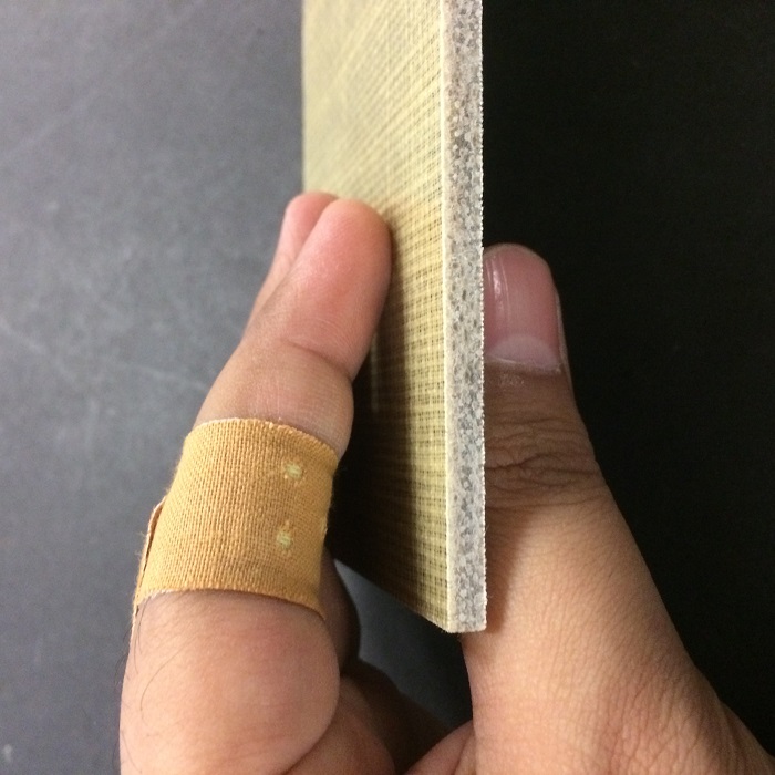
Since the 3d that I made is appropriate as the inside mold, I will have to now create it's outer mold that would ensure compaction. I learned from the coupon I made that nine layers of natural fabric when infused with resin yields a surface that is roughly 4 mm thick. So, I have spaced my outside mold accordingly.
To create the mold I simply had to offset the surface by 4mm usign OffsetSrf Command. Then, I created a reactangle of size 320mm x 320mm using Reactangle Command. Now, using Move command I shifted it by 55mm. The using Loft Command I created polysurfaces between the two geometries. The next step is to join all the surfaces, for that I used my favourite command BooleanUnion. Once the closed single model is there, I flipped it upside down to place both inside mold and outside mold side by side. For detailed design workflow, please check following commands I employed for creating the mold.
Preparing Drawings for Laser-cutting the fabric
To cut fabric that could take the 3D form shown above, it is first required to unroll the surface of the 3D and then laser cut them. To do so, again I used rhino 3d. I simply used UnrollSrf Command.
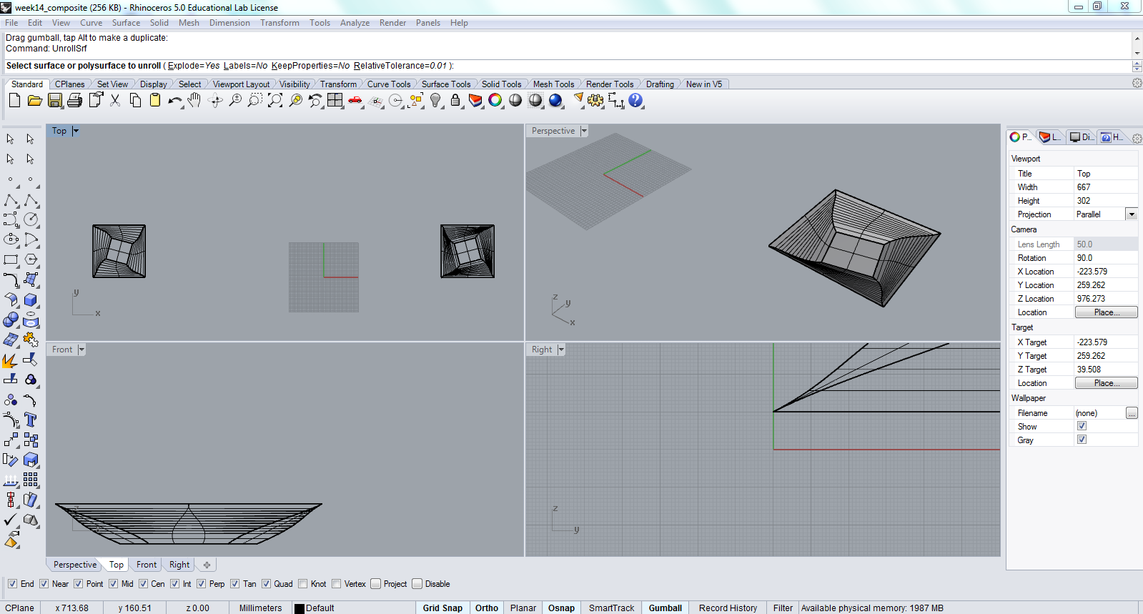
First select the object and type "unrollsrf" and push enter to get the 3D surfaces unroll in one plane. Its this simple.

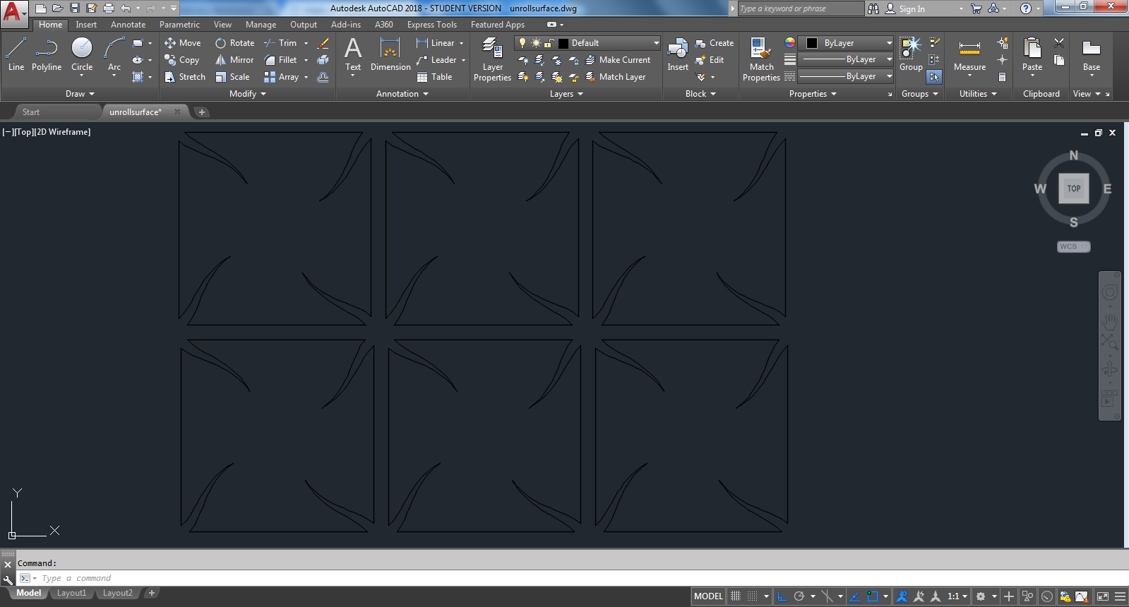
Then I exported it as 2D drawing which I then opened in Autocad. Since the unrolling of surface yeilds polysurfaces arranged linearly, it cannot be used right away for laser cutting. It needs some more work to be done. Once the file got opened in autocad, again I had to a set of simple commands to prepare it for futher stage. I decided to keep the small rectangle at the top, to be at the center connecting all four sides, as it's limbs. First I created the rectangle of 150mm x 1500 mm using Rectangle Command, then I moved all the four sides using Align command and aligned the shorter side to the rectangle I created. Later, I removed the central rectangle, which I drew as a reference to bring all the unroll surfaces together. Now at last, I copied it using Copy Command and pasted it as many times as I wanted. The profile can be seen in the following image:
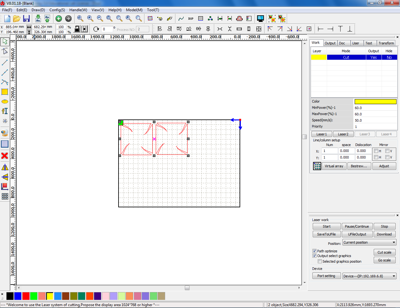
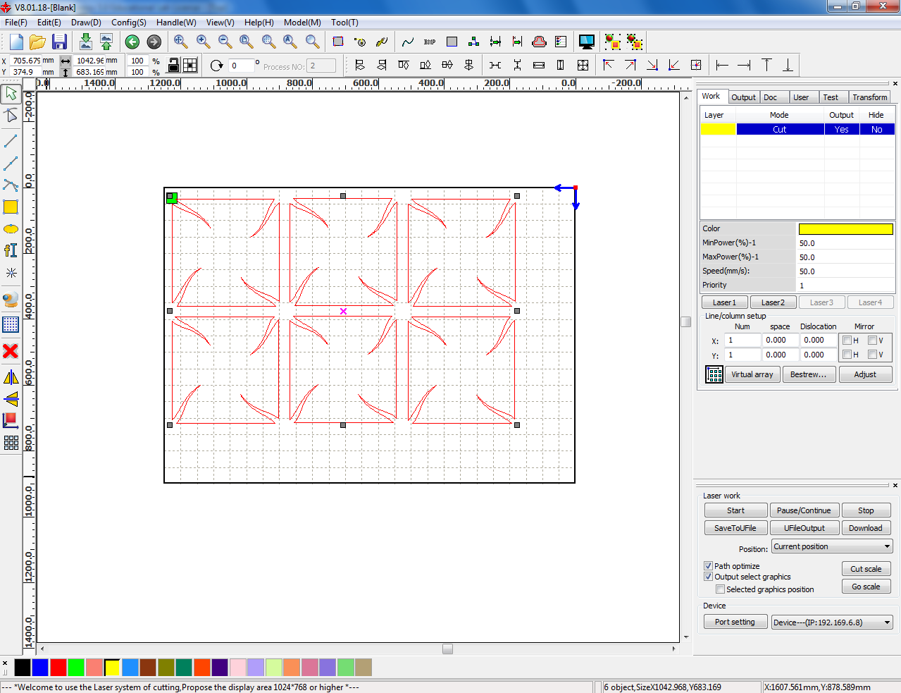
RDWorks and Laser Cutting
As demonstrated in week 3- laser cutting exercise, I religiously followed all the steps that are required for successful laser cutting. Following are the parameters that I had set to cut the fabric.
Following parameters are for laser cutting of khadi fabric:
Following parameters are for laser cutting of thinner burlap:
Following parameters are for laser cutting of thicker burlap:
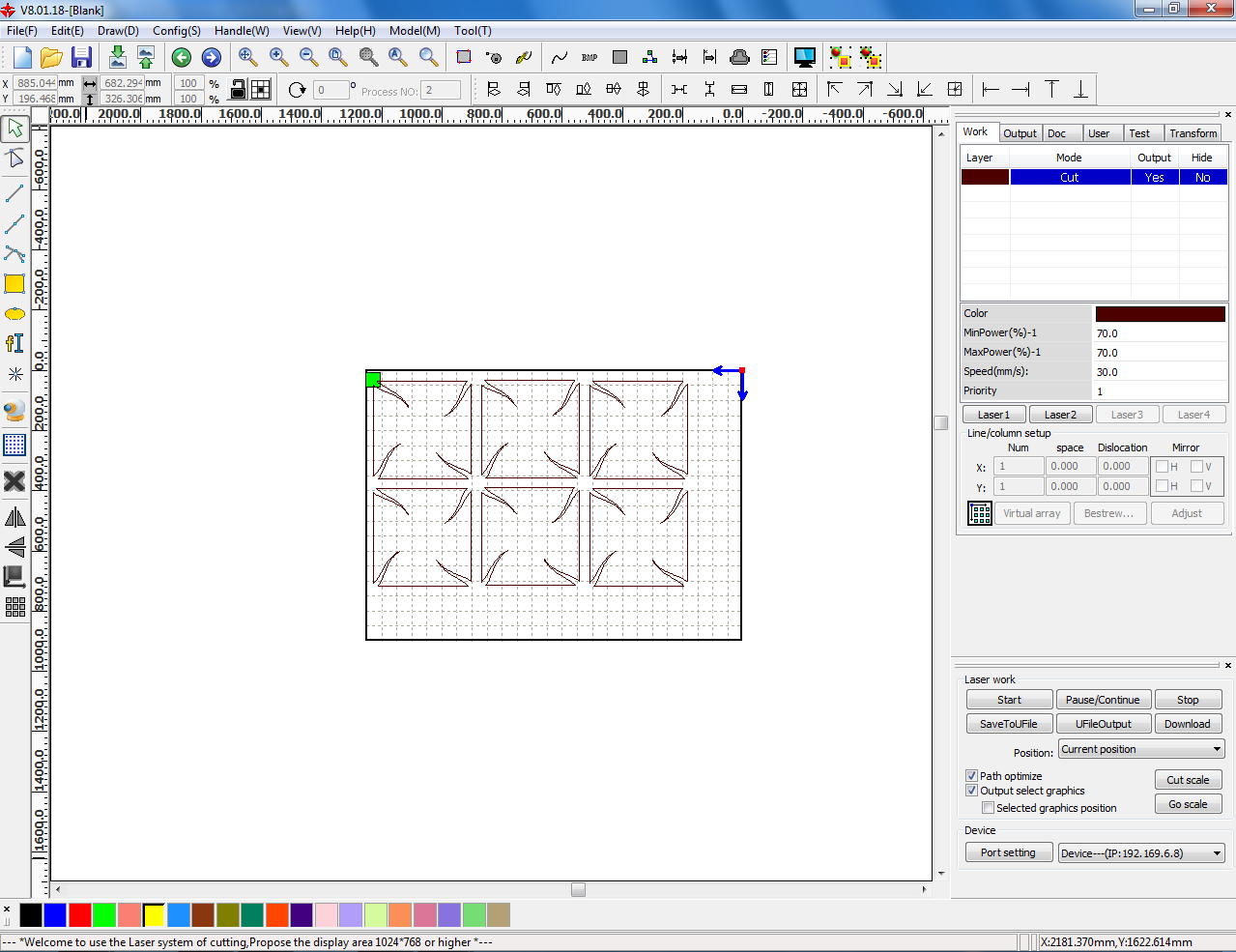
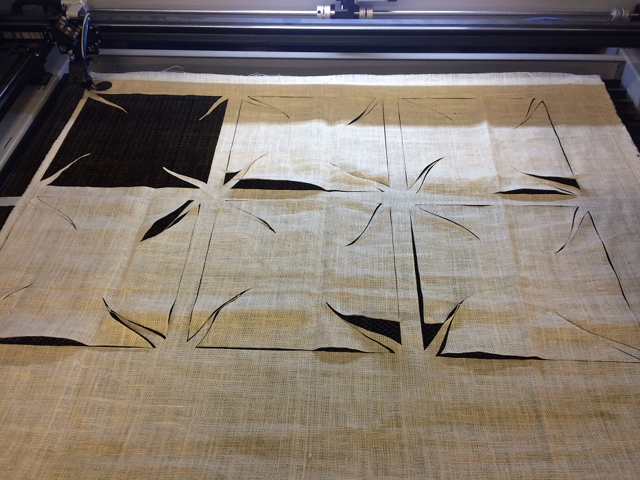
Basically, for laser cutting a fabric, I ensured that the power is not too much and the speed is not too less. For khadi and thinner burlap the power to speed difference is kept close to avoid burnt edges, where as in case of thinker burlap 'jute' the difference is increased. This was done beacuse jute has numerous thick fibres which needs more power to cut them through. Below two images are of laser cut burlap.

CNC Machining
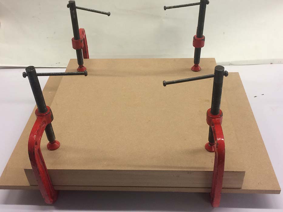
11mm tk MDF x 5no.s are glued together to create the base material for 3D milling of mold-1, where as base material for mold-2 is made out of 18mm tk MDF x 3no.s.

a. Toolpath: Following are the screenshots of the toolpath that I created for roughing, finishing and cutting the material.
Orientate and Size Model: In partworks 3D, I defined the orientation of the model by selecting the correct face of the .stl model as the top surface. And then I specified that machining is to be to be done only on the top side.
Material Size and Margin: In this screenshot I defined the origin point, the depth of the model from the top surface and the bottom surface of the model, which is known as a cut plane.

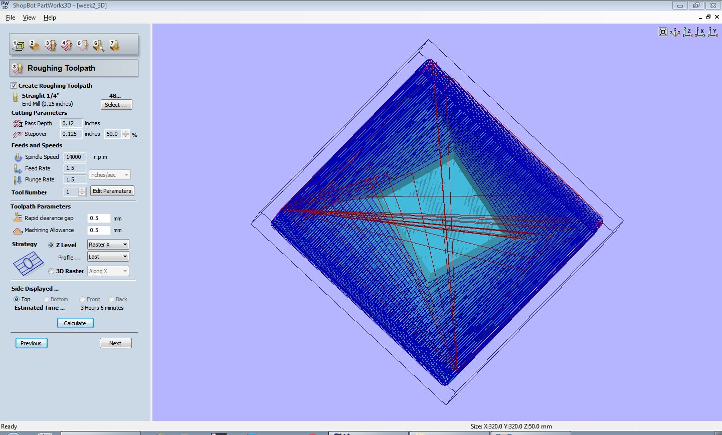
Roughing Toolpath: Key parameters in the roughing toolpath are-
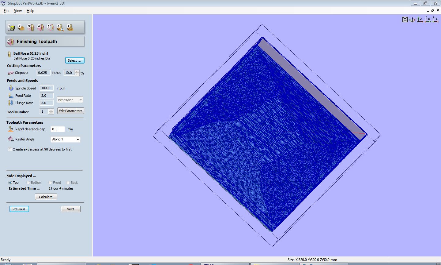
Finishing Toolpath: Key parameters in the finishing toolpath are-
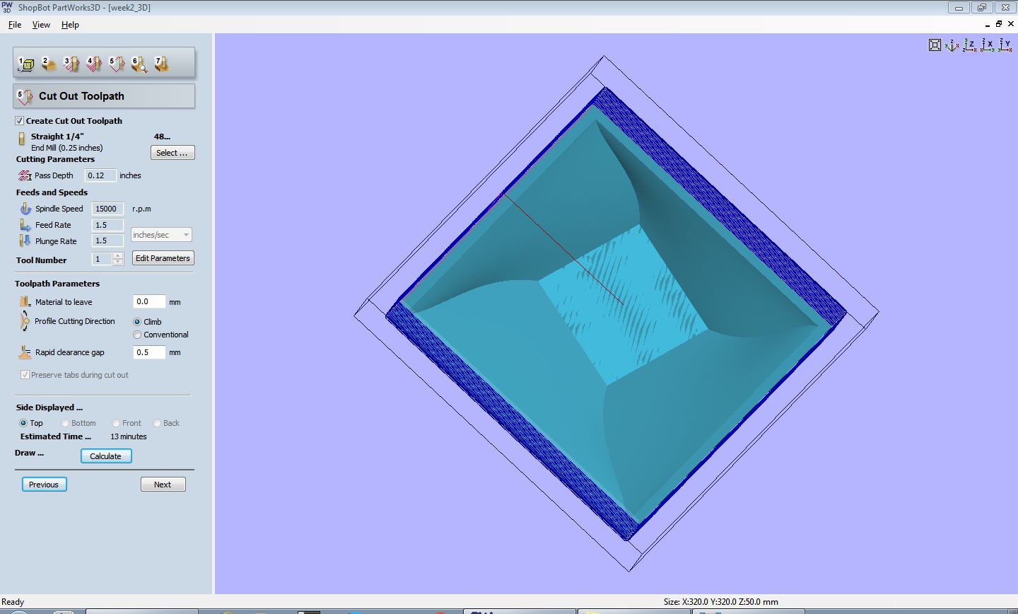
Cutout Toolpath: It meant to cut out the actual model from the stock material, if it is bigger than the model. Following are the key parameters for it-
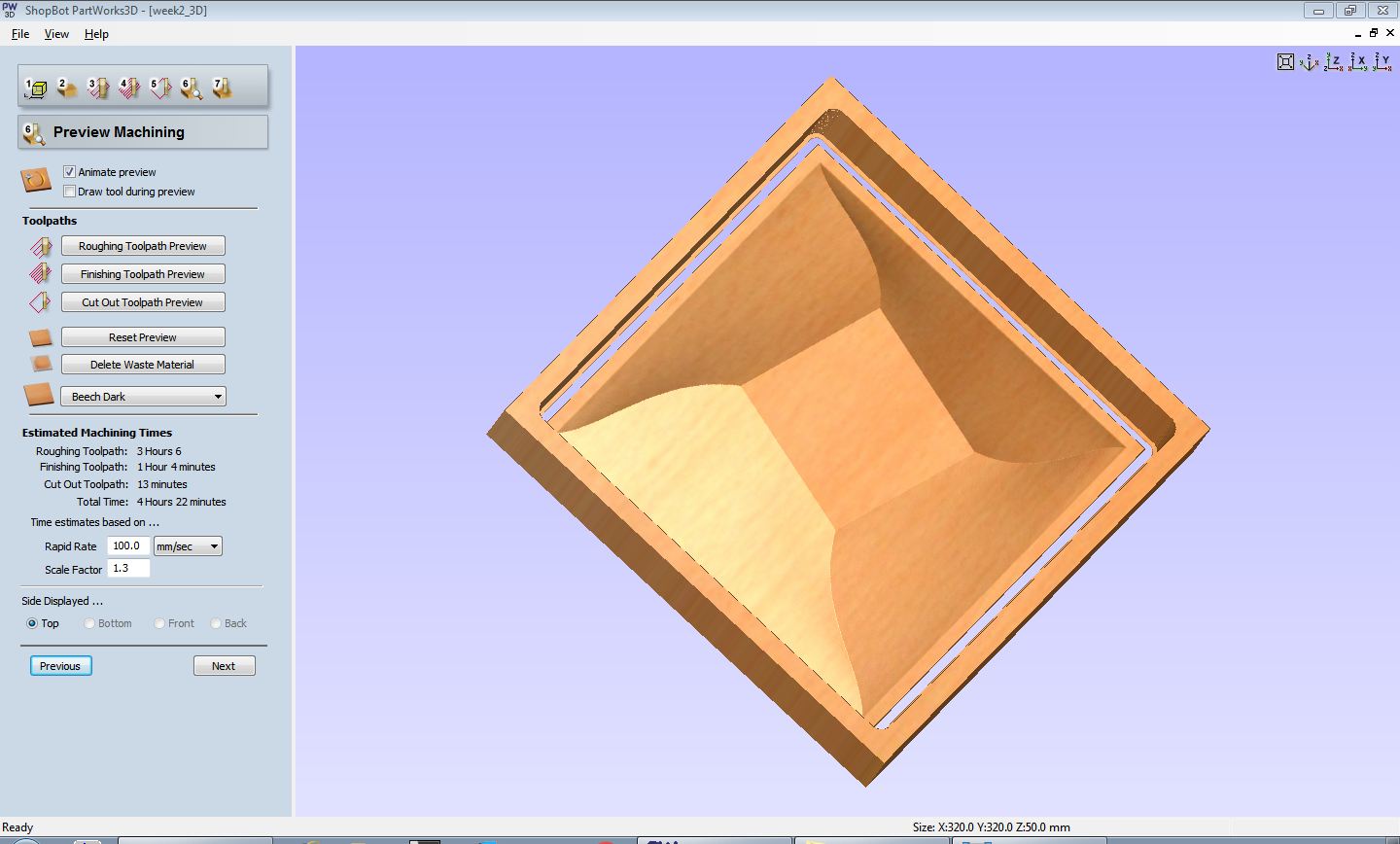
Preview Machining: This stage of creating toolpath provides with a simulation of roughing, finishing and cut out toolpaths, ensuring if the desired milling is going to happen or not.
Save Toolpaths: To this page saves toolpath in .sbp format that is good for milling.

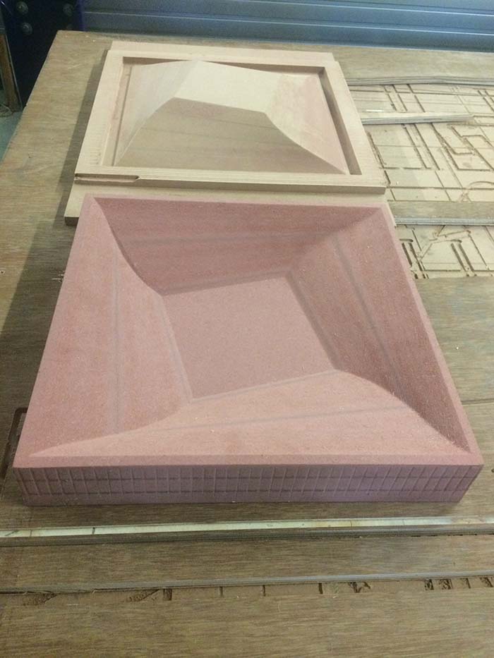
b. Milling: After Setting up the machine, and mounting the base material on the sacrifice board, I started milling on CNC. Following are the final milled molds to be employed later for compaction.
I used similar process of creating toolpath for mold-2, (outside mold) and was successfully able to mill it. The only difference lies in mold-1's milling and mold-2 is the use of cut out toolpath. As I mentioned above that I made cut out toolpath for mold-1 but did not actually applied it so that I can handle the mold. In case of mold-2, cut out toolpath could have easily been avoided, but I wanted to see the process and learn. So I used the for mold-2. Mold- 2 toolpaths are included in the week14 files.
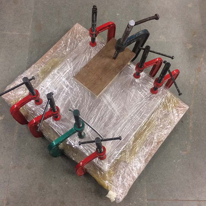
Layering, Infusion and Compaction
Coupon making process helped me get hold of the entire process of composites, I followed same steps that I employed for coupon. Following are a few pictures of the process. I am using the same epoxy resin that I used for coupon building. So I mixed resin and hardner in the same proportion of 100:80 by weight.


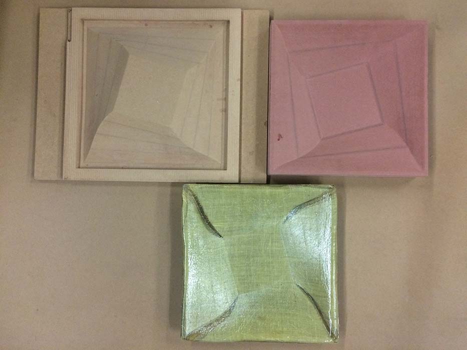
Final Object

Links
Week 14 FilesSaftey Data-Sheet and Technical Data-Sheet for Resin
Araldite Website