Week 13: Input Devices
Tasks for the week:
- Measure something: add a sensor to a microcontroller board that you have designed and read it.
For Final Project: Button
Task:01
Designing the Board
For my final project, I plan to use two end stoppers on my extruders as input devices. Since I am planning to use a syringe, my idea was to add two switches such that once the moving plane hits the top button, it would start counting the steps, after hitting the next button, it would go back.
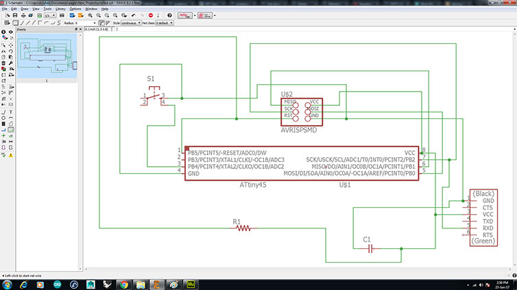
Hence, for this week's assignment, I tried making a board where I can recieve data by pressing button.To begin with I referred to the board diagram given on the class's site and started by making the schematic.
The datasheet for Attiny 45 helped me understand that Attiny 45 has a simpler layout and a smaller footprint as compared to Attiny 44. This helped me to have a board with lesser components tha can work with lower power also as compared to that of Attiny 44.
Components:
AVR ISP 6 pin header
Attiny 45
FTDI header
10k Resistor
1uF capacitor
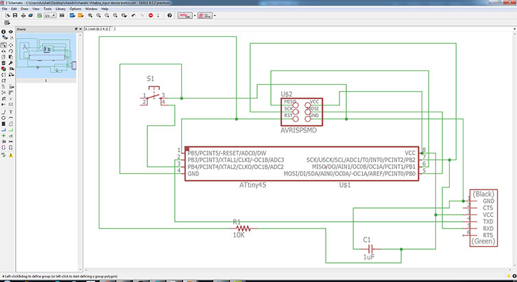
The only modification I made to the circuit is to connect the TX pin to the attiny 45 so as to allow a two-way communication between the RX-TX pins.
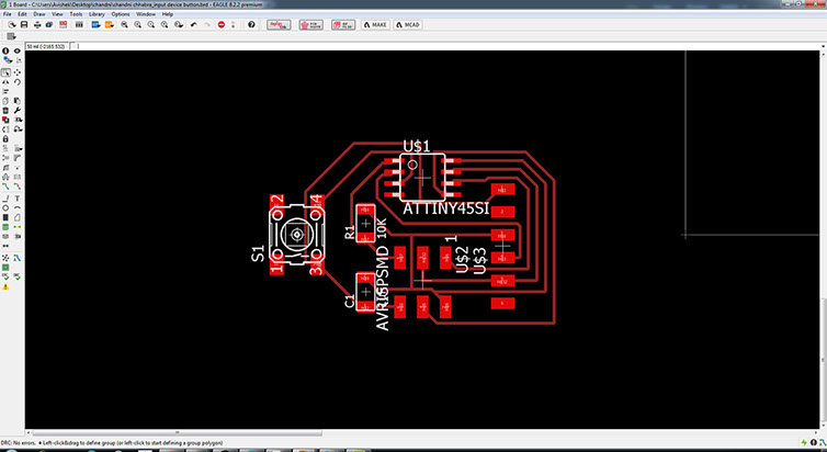
Next, I autorouted the components in the boards diagram and checked wwith the design rules. It showed 'No errors.
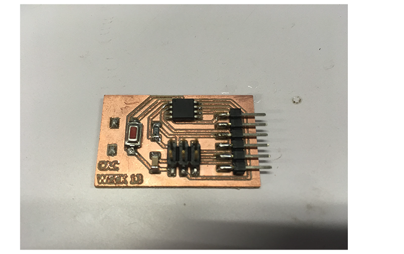
After finishing the board diagram, I proceeded towards milling and stuffing the board.
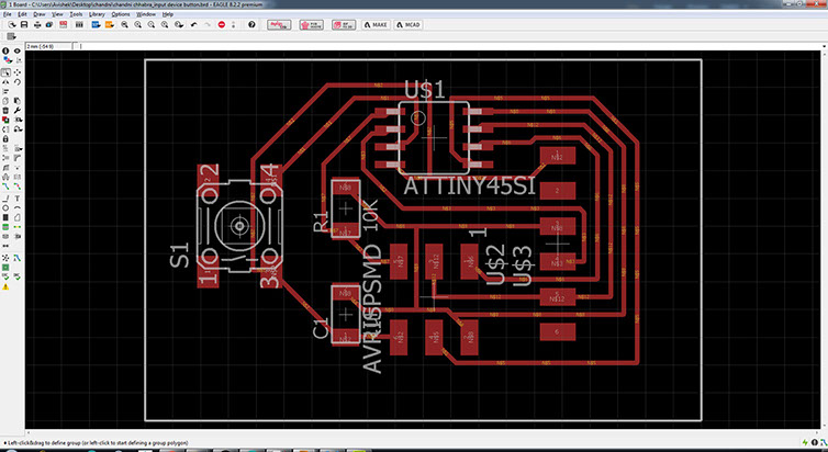
Below, are the png images for my board that I used for milling and stuffing. EAGLE files can be acessed here.
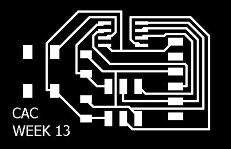

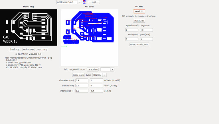
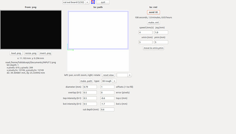
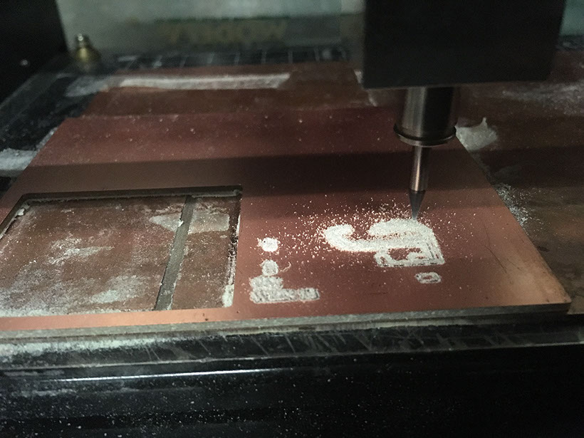
Below, are a few images that show the parameters I used for milling the board and the process of milling:
<
>
Task:02
Programming the Board
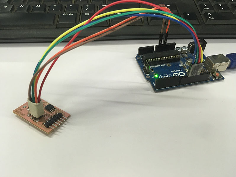
For programming the board, I first prepared my Arduino to work as ISP. Next, I connected the MISO, MOSI, SCK, RST, GND and VCC pins of my board to the arduino for programming.
ISSUES I fixed:
Next, I uploaded the code but was unable to get data on the serial monitor. Hence to verify the issue, I first burnt the bootloader on my board run the basic code for RX-TX communication to get data on the serial monitor . The image showing the working can be seen below the codes.
I used the following codes:
#include <SoftwareSerial.h>
#define rxPin 3
#define txPin 4
SoftwareSerial serial(rxPin, txPin);
void setup() {
pinMode(rxPin, INPUT);
pinMode(txPin, OUTPUT);
serial.begin(9600);
serial.println("A");
}
void loop() {
serial.print("s" );
delay(100);
}
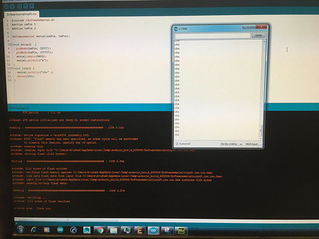
Next, I uploaded Neil's code onto my circuit. Now, it worked perfectly. It gave 'd' and 'u' on the serial monitor when I pressed the button. The video below shows the working of the board.
Option for Final Project:
Distance Sensor
Task:01
Designing the Board
For this week's assignment, I also made a board, that can sense diistance.For this, I referred to the board given by Neil on the class site. I wanted to try the distance sensor, because I kept using this as an option for for my Final Project. The idea was to use this instead of the button to stop the motor when it senses a certain range of distance.
I starte by designing the board. The screenshots below explain my process:
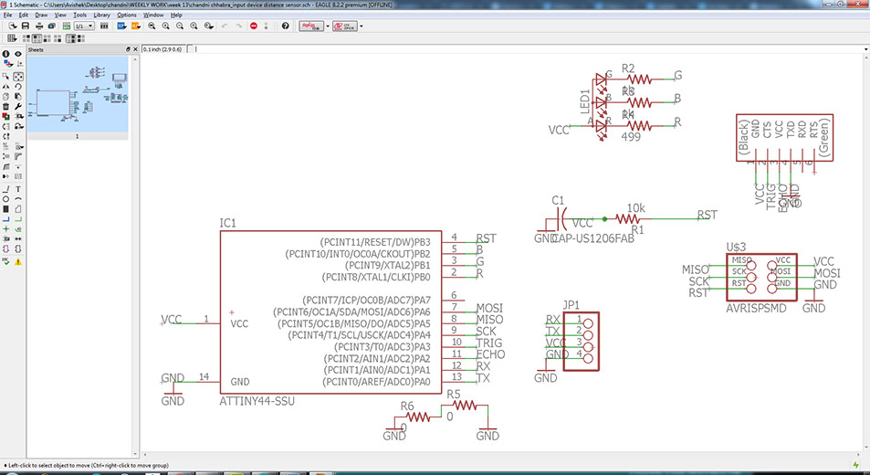
The above image shows the schematic of my board. I added extra 4 pins of RX, TX, VCC and GND for the possibility of using the circuit by networking for my final project.
Components:
Attiny 44
1uF capacitor
10k Resistor
0ohm resistor- Qty 2
499ohm Resistor
Ultrasonic Sensor
AVR ISP 6 pin header
4 pin male header
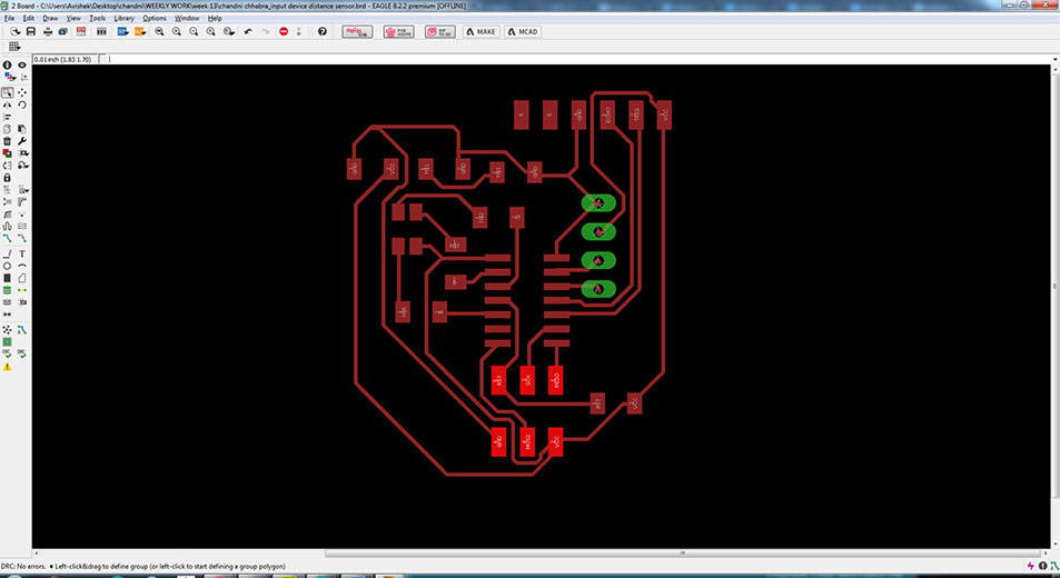
Next, I arranged the componets and auto-routed it. Further I checked it by the design rules and it showed no errors. The 'No errors' message can be seen in the bottom tab of the image above.
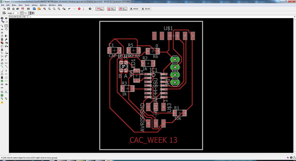
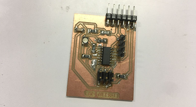
The above image shows the final prepared diagram of my board. Next, I moved to the milling and stuffing the board.
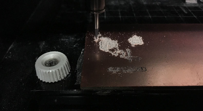
Below images show the parameters I used for milling the board:
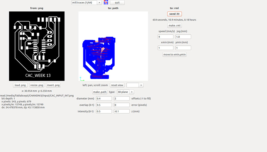
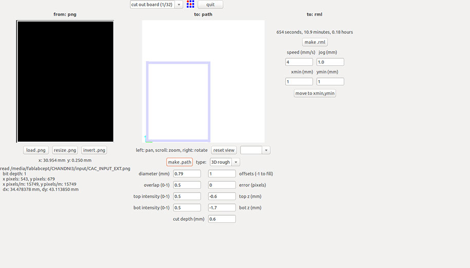
Below images show the milling process and stuffed board:
<
>
Task:02
Programming
For programming the board, I prepared my Arduino Mega to work as ISP. It is not necessary to use Arduino Mega to program the board. But, since it was available, I used it. Next, I connected my board with arduino using the MISO,MOSI, SCK, RST, GND and VCC pins.

The above image shows the connections I made from the AVR ISP header of my board to the arduino for the purpose of programming.
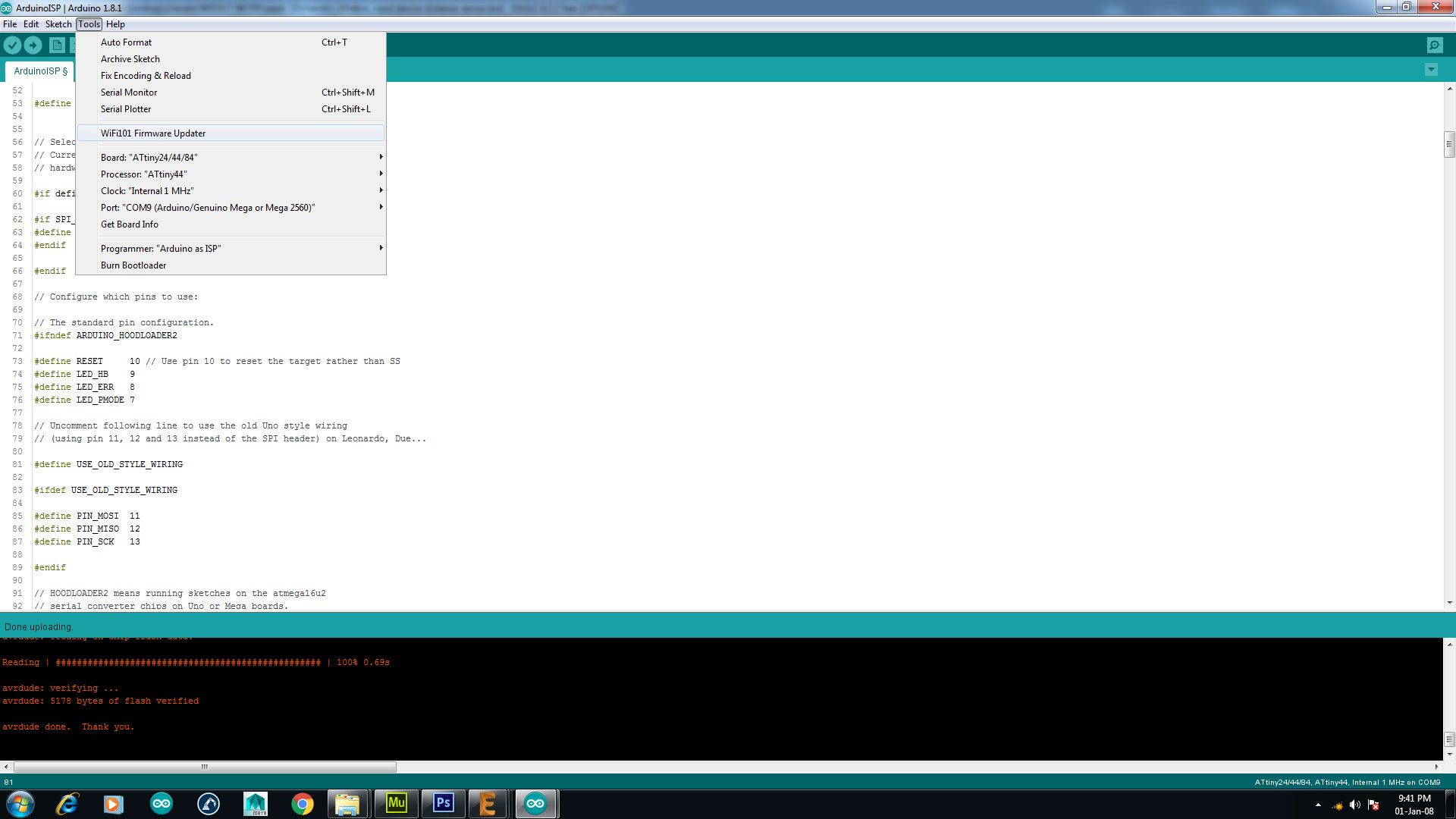
Next, I selected the following from the tools menu and burnt the bootloader on my board.
Next, I pasted the following that lights up a LED based on the distance mapped by the sensor. This is why I used an RGB led to have the output of the data read from the ultrasonic distance sensor.
I uploaded the code by mentioning the pin numbers of the LED and distance sensor as follows:
int led = 8 ;
int led2 = 9 ;
int led3 = 10;
int trigPin = 3 ;
int echoPin = 2;
On uploading the code, The led lighted up to the value that I mentioned in my code to be constant.
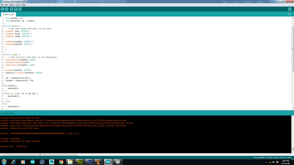
The above image shows the successful uploading of the code on my board.
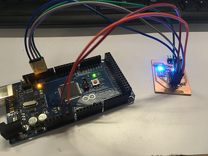
The image shows the lighting of the LED on uploading the code.
Code I used for the board:
int led = 8 ;
int led2 = 9 ;
int led3 = 10;
int trigPin = 3 ;
int echoPin = 2;
long duration, cm , inches ;
void setup() {
// put your setup code here, to run once:
pinMode (led, OUTPUT) ;
pinMode (led2, OUTPUT) ;
pinMode (led3, OUTPUT) ;
pinMode(trigPin, OUTPUT) ;
pinMode(echoPin, INPUT) ;
}
void loop() {
// put your main code here, to run repeatedly:
digitalWrite(trigPin, HIGH);
delayMicroseconds(10);
digitalWrite(trigPin, LOW);
pinMode(echoPin, INPUT);
duration = pulseIn(echoPin, HIGH);
cm = (duration/2)/29.1;
inches = (duration/2) /74;
if(cm<10){
burnled();
}
else if ( cm > 10 && cm <20) {
burnled2();
}
else
{
burnled3();
}
delay(250);
}
void burnled(){
digitalWrite(led,LOW);
digitalWrite(led2,HIGH);
digitalWrite(led3,LOW);
}
void burnled2(){
digitalWrite(led,LOW);
digitalWrite(led2,LOW);
digitalWrite(led3,HIGH);
}
void burnled3(){
digitalWrite(led,HIGH);
digitalWrite(led2,LOW);
digitalWrite(led3,LOW);
}
Stating the pins on the board that are connected to the Attiny 44 micro controller
Setup for lighting up the LED when data is read from the sensor
Creating an output via lighting the coloured LED in reference to the distance sensed by the sensor.
The below video shows the working of my board based on the codes I uploaded:
Step:01
Milling the FabISP
To start milling the FabISP , I first understood the method of working using Ubuntu (basics).So I documented each step of opening a file and creating .rml file for milling.
Step:01
Milling the FabISP
To start milling the FabISP , I first understood the method of working using Ubuntu (basics).So I documented each step of opening a file and creating .rml file for milling.

EX-TERRA-DUR by Chandni Chhabra is licensed under a Creative Commons Attribution-ShareAlike 4.0 International License.