Week 8: Embedded Programming
Tasks for the week:
- Read a microcontroller data sheet.
- Program your board to do something, with as many different programming languages and programming environments as possible.
This week the first task was to read the micro controller data sheet. So I started with it. Since, I am new to electronics, I didn't understand much when I started then my fellow fab-acdamiean Gautam Prakash helped me understand it.
The first page helped me understand the features of the ATTiny. Next page is the Pin diagram. This page was very helpful. It helped me understand as to what pin of the ATTiny links to what. Next all the pins have been described in detail. It helps for a new person like me to understand the micro controller better.
I realized the importance of reading data sheet after reading this one, as it helped me understand the reason behind using a micro-controller. There were a few things that I felt were interesting to understand through this data sheet. The images of those pages are below:
.jpg?crc=4120200583)
.jpg?crc=208739479)
.jpg?crc=522732989)
.jpg?crc=4095451047)
.jpg?crc=265477757)
Questions that need to be answered:
How can I register more effectively.
Programming the board:
Choosing Arduino over FabISP
I tried installing the Atmel suite on my windows pc to use FabISP to program the board. But there were bugs in the software that was creating issues in my system. I tried learning working in Linux, but since I dont have much experience with linux, I find working in windows better. Hence,I chose to move forward with Arduino to program my boards.
Task:02
Programming the board
Step:01
Preparing Arduino as ISP:
For this I connected the Arduino Uno to my PC and followed the steps in ARDUINO IDE as below.
Arduino IDE:
"The Arduino IDE supports the languages C and C++ using special rules of code structuring. The Arduino IDE supplies a software library from the Wiring project, which provides many common input and output procedures. User-written code only requires two basic functions, for starting the sketch and the main program loop, that are compiled and linked with a program stub main() into an executable cyclic executive program with the GNU toolchain, also included with the IDE distribution. The Arduino IDE employs the program avrdude to convert the executable code into a text file in hexadecimal encoding that is loaded into the Arduino board by a loader program in the board's firmware."- Wikipedia
.jpg?crc=16363819)
First, I selected the codes for 'Arduino ISP' from 'Examples' tab in the 'File' menu after opening Arduino IDE.The above image shows the interface of Arduino IDE and
.jpg?crc=3775252218)
After that, I scrolled down to Line 81: "// #define USE_OLD_STYLE_WIRING". Here, to uncomment this line, I removed the "//".
.jpg?crc=525310404)
The code displayed the pin numbers where I needed to connect the AVR ISP pins from my board later.
.jpg?crc=438875999)
Next, I went to tools menu, and selected 'Arduino Uno' from drop down menu in the 'board' option.
.jpg?crc=3901735385)
Next, I selected 'AVRISPmkll' in programmer option and uploaded the code.
.jpg?crc=4290447479)
Next, I uploaded the code on the Arduino Uno. After it was done, the message 'Done Uploading' appeared.
Step:02
Programming the Hello Echo Board
Now, I connected my board to the Arduino by connecting pins from the 6 pin header of the board to the pins on the arduino. In the previous code that was uploaded on Arduino showed the number of pins on Arduino that corresponded to the pins of the 6 pin header on my board.It can be seen below:
.jpg?crc=34317363)
The image below shows the connections from my hello echo board and Arduino UNO.
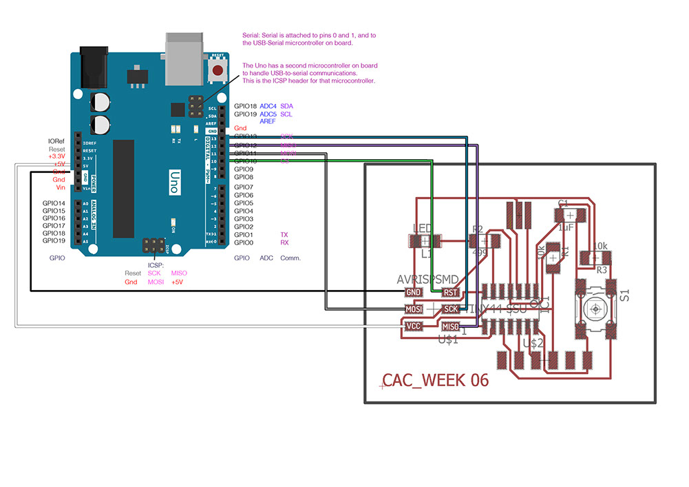
I used Male to Female head jumper wires to make connections by colour coding them as follows:
GND: Black
VCC: White
MISO: Grey
MOSI: Purple
SCK: Blue
RST: Green
Next, I opened the codes for 'Button' from 'Examples' tab from 'File' menu as seen below:
.jpg?crc=4054225606)
Before uploading code to my board, I downloaded the boards data for 'Attiny' by referring this link.
Next, I set the button and Led pin number by referring the Attiny pins on my circuit to which the button and led were connected.
Button pin: 3
Led Pin:7
951x535.jpg?crc=323072224)
.jpg?crc=390409285)
Next, I made following changes in the tools menu to upload the code to my circuit.
The changes can be seen in the image below and uploaded the code:
Below is the button code working on my circuit. The LED blinks when I press the button and stops when I release it.
Next, I edited the code to reverse the action. As per my edited code, the LED stopped blinking when I pressed the button. The edited code is as below:
const int buttonPin = 3; // the number of the pushbutton pin
const int ledPin = 7; // the number of the LED pin
// variables will change:
int buttonState = 0; // variable for reading the pushbutton status
void setup() {
// initialize the LED pin as an output:
pinMode(ledPin, OUTPUT);
// initialize the pushbutton pin as an input:
pinMode(buttonPin, INPUT);
}
void loop() {
// read the state of the pushbutton value:
buttonState = digitalRead(buttonPin);
// check if the pushbutton is pressed.
// if it is, the buttonState is HIGH:
if (buttonState == LOW)
{
digitalWrite(ledPin, HIGH); // turn the LED on (HIGH is the voltage level)
delay(500); // wait for a second
digitalWrite(ledPin, LOW); // turn the LED off by making the voltage LOW
delay(500); // wait for a second
} else {
// turn LED off:
digitalWrite(ledPin, LOW);
}
}
Below is the video showing working of the edited code on my circuit:

EX-TERRA-DUR by Chandni Chhabra is licensed under a Creative Commons Attribution-ShareAlike 4.0 International License.