_Week06_ELECTRONICS DESIGN
_Introduction
In this week we get an introduction to Electronics Design going through redrawing a board in a electronics design software in order to make a new board learning outcomes like circuits and its parts (VCC, GROUND, current flow), components (resistors, capacitors, LED) and different ways to solve circuits.
_Background
Electronics design is based on the calculation of the components within a circuit to achieve its operation, this has to do with the amount of current that passes, the polarity of its components and the order in which it is arranged
This was my first time in Electronics Design so I read several articles about electronics in general for understanding what I was about to do. I leave the links here:
_Week Assignments
_Workflow /Step by Step
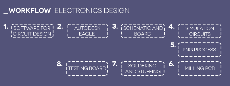
_Software for electronics design.
The electronics design software helps us to create the circuits from two views: schematic and board, each one helps us to order correctly and it facilitates the manufacture of the board. In this case I used Autodesk Eagle to re-draw the echo hello-world for the assignment.
For our projects, the electronics design workflow is generally a two-step process:
- 1.Designing circuit in schematic editor, optionaly simulating with capable tool.
- 2.Component placement in board layout editor and route traces, manually or with autorouter
Others softwares useful:

_Autodesk Eagle.
Eagle is a free open PCB design software recently acquired by Autodesk, allows us to design our board by working with a schematic editor and board editor in which we enter the necessary components and we are interconnecting them in the correct order.
First, I downloaded Eagle and install the software in my computer to later create a new project.
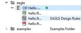
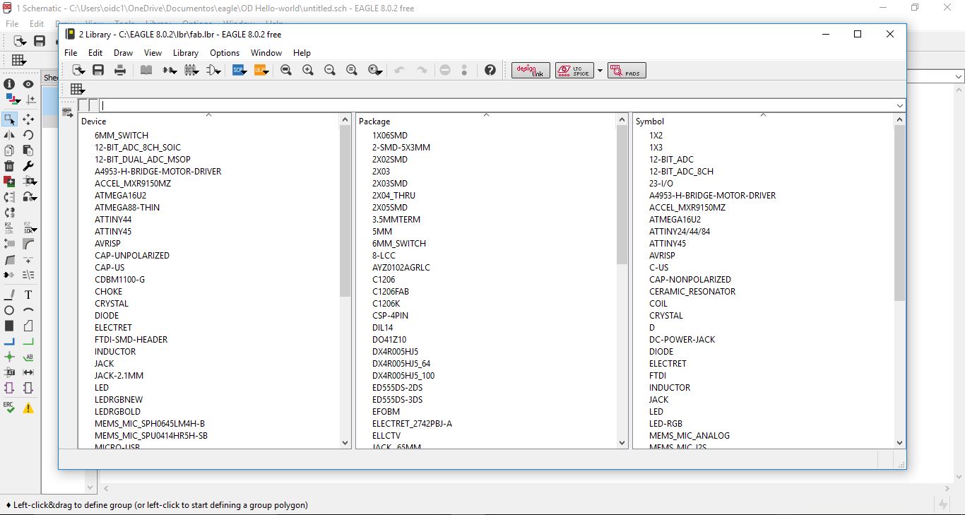
I opened a new Project/Schematic and downloaded the fablibrary that have most of the components for Fab Academy boards, To bring fab.lbr into Eagle, simply download the library and copy it to the Eagle library folder.
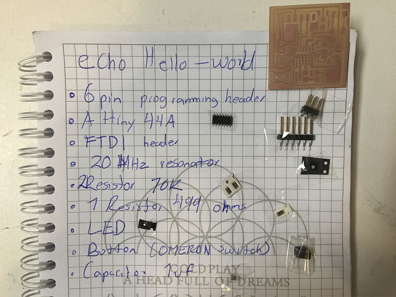
List of components for Echo hello-world board:
- 6-pin programming header
- ATtiny44 microcontroller
- FTDI header
- 20MHz resonator
- Button (OMERON switch)
- Ground
- Resistor 10k
- Resistor 499Ohm's
- VCC
- LED
- Capacitor 1uf

To start working in Eagle, I used the following commands:
ADD for  adding components to the diagram
MOVE for moving items
NET for linking traces
NAME for giving names to each link
LABEL for conecting different links (dont have to be visible)
VALUE for giving a amount to the item
JUNCTION for adding a junction between wires

NOTE Be secure and verificate to do correctly the JUNCTION, NAME, LABEL for all the pins.
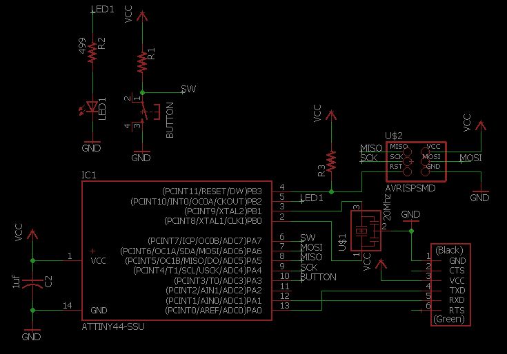
_Schematic and board.
For working in the schematicfor adding all the components and do the correct connections of each item in orded to switch then to the board layoutfor reorder all the items as they gonna be at the PCB for the milling.
To change to the board layout
Menu >> File >> switch to board
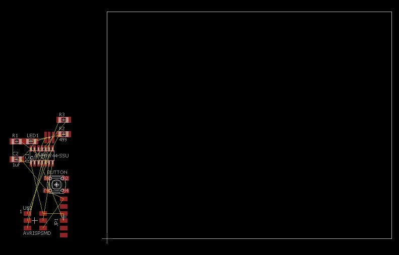
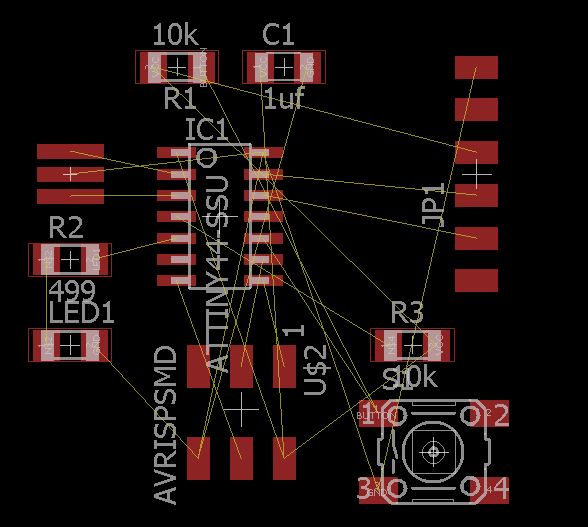
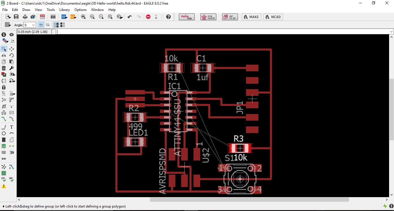
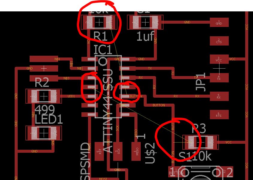
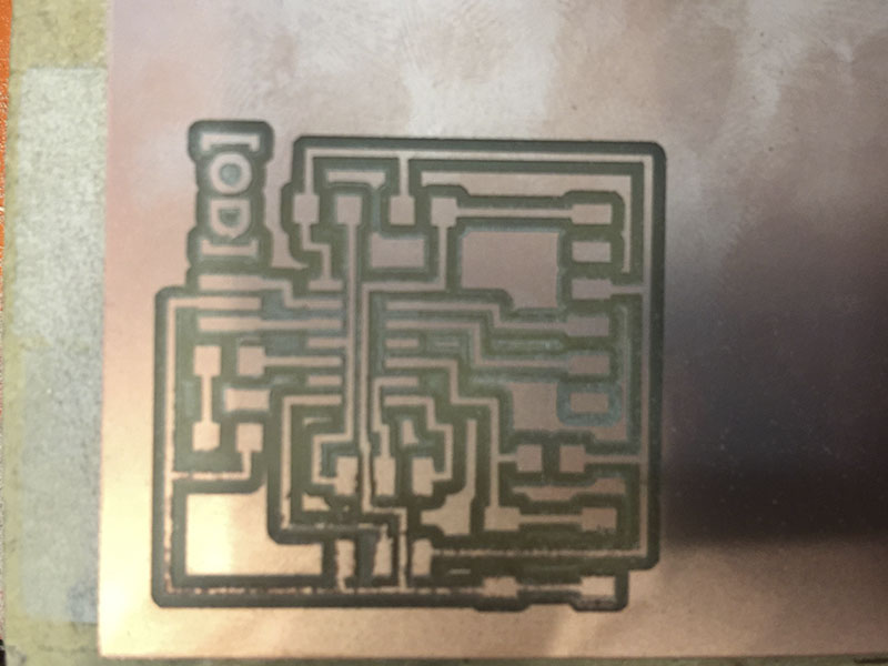
When I changed to the board layout for the first time the items appeared like this so I had to reorder each one creating the correct traces for the milling (no trace can cross other).
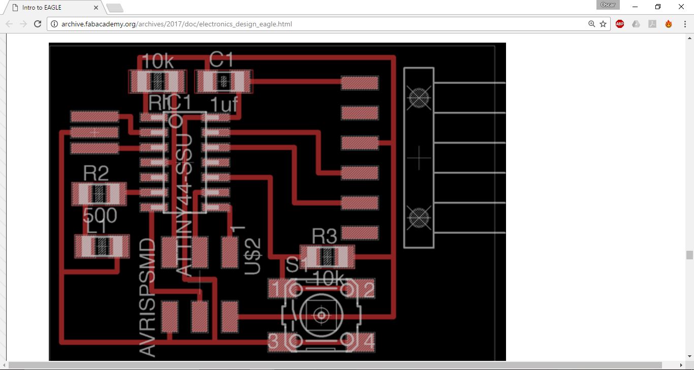
After trying several times to sort all the items I realized that it was not going to be able to somehow (after seeing 3 different tutorials tried to do it my way but I lost a lot of time) so I decided to return to the schematic view and order them as shown in this tutorial.
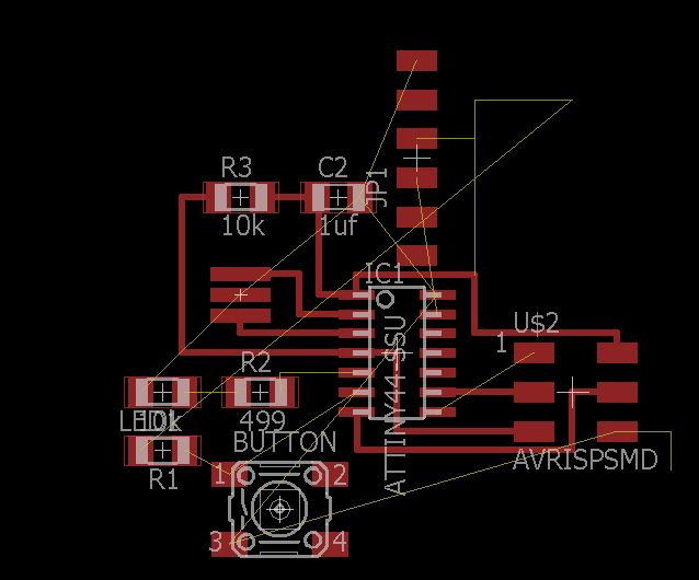
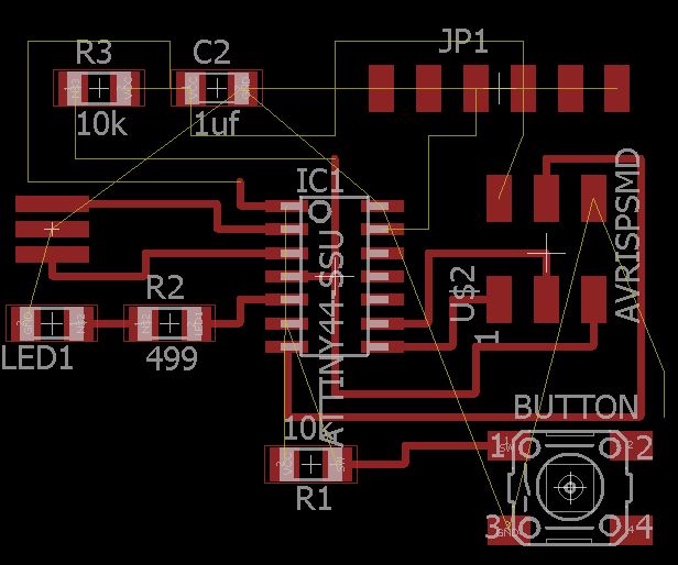
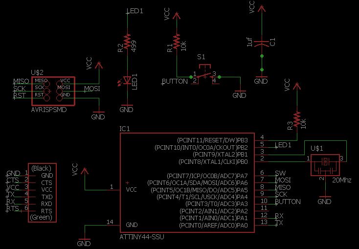
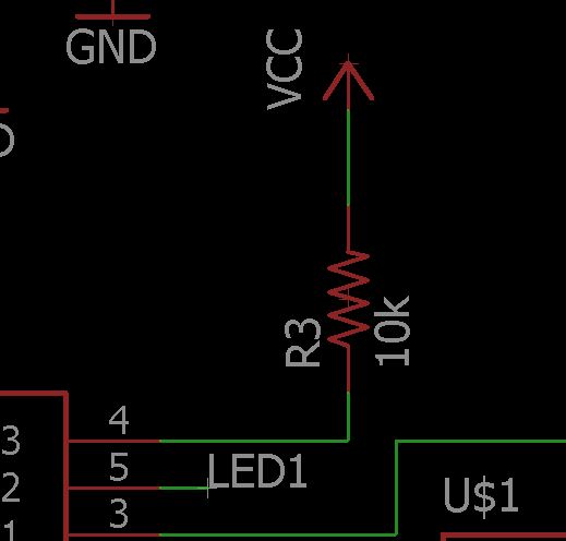
So when I rearranged everything in the schematic view I noticed an error in the resistor connections in the order they were connected and where they were.


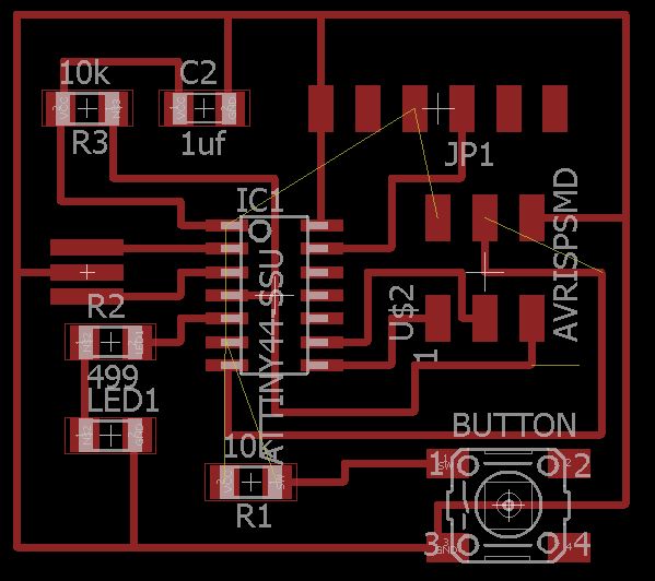
After that everything was in order check the design rules:
TOOLS >> DRC >> out 16 mill in all the values
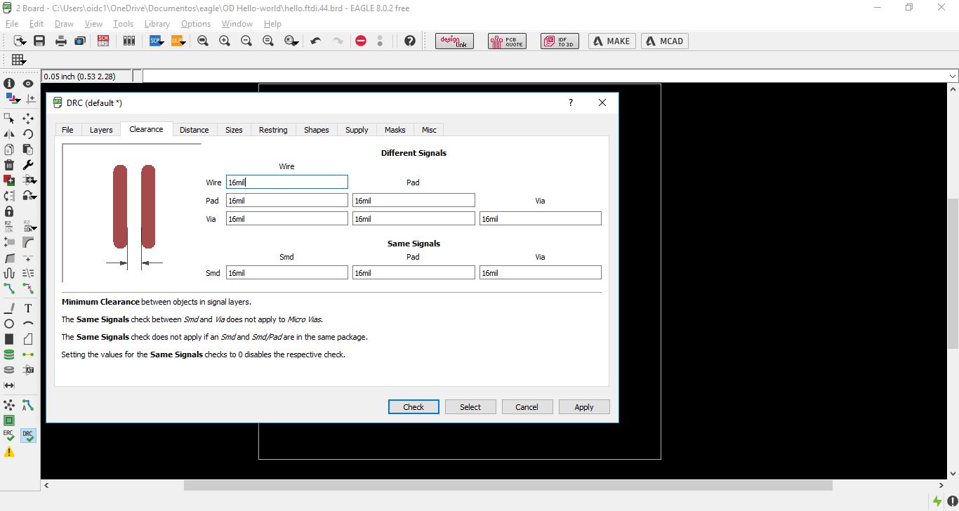
TOOLS >> DRC >> check cleareances
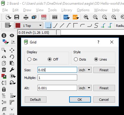
GRID >> change size 0.05 for solve the cleareances.
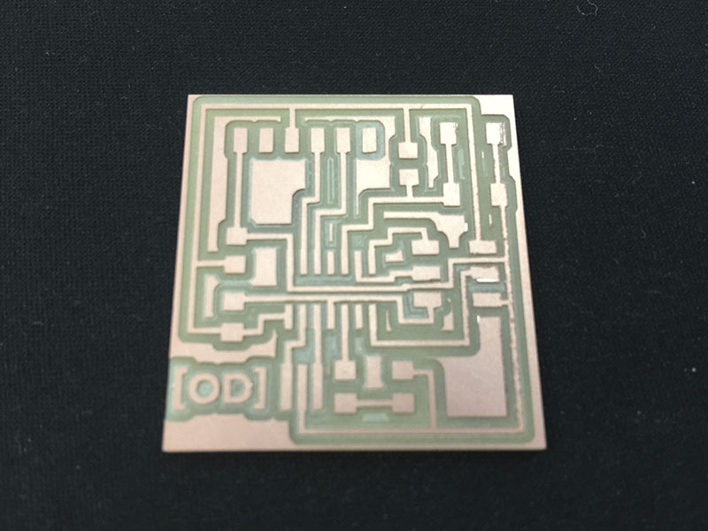
Final board

_Export and PNG process.
I exported as EPS because in the new version of the Eagle the direct PNG goes wrong in the milling process, so I did another process in Adobe Photoshop.
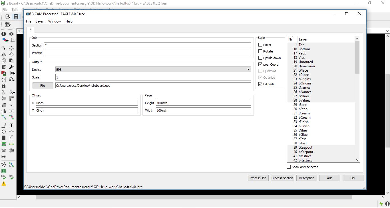
Exported first the TOP layer for the traces, and the DIMENSION layer for the outline.
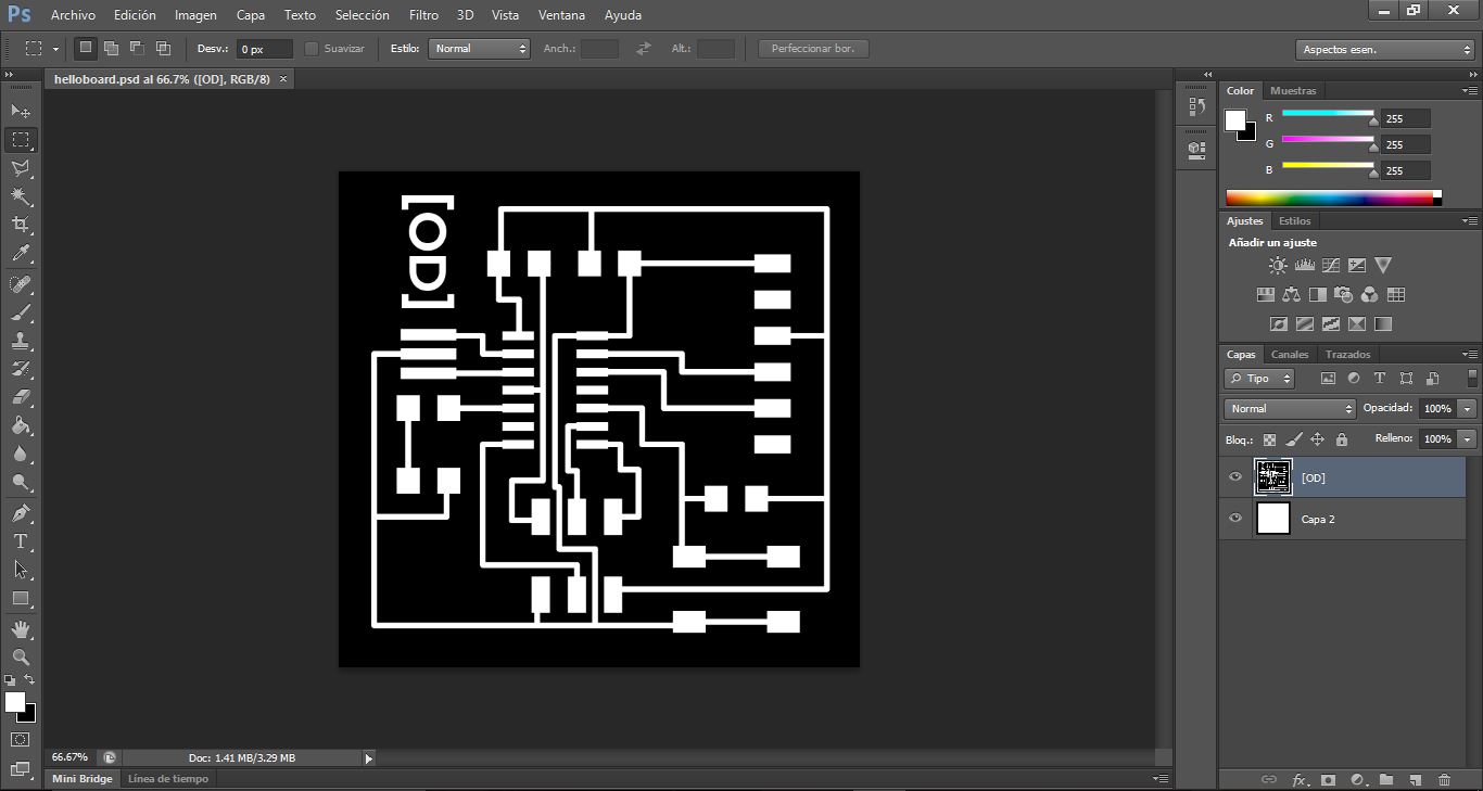
In Adobe Photoshop I created other layer for the outline so in order to create the inverse and export the two PNG files.


_Milling PCB
For the milling process I worked with the Roland Monofab SRM-20 and create the gcode in FabModules and then I followed this steps:
For create the gcode from FabModules:
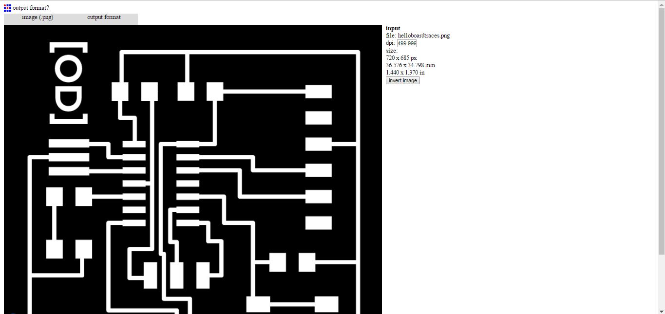
- Import the PNG files to the FabModules in INPUT FORMAT
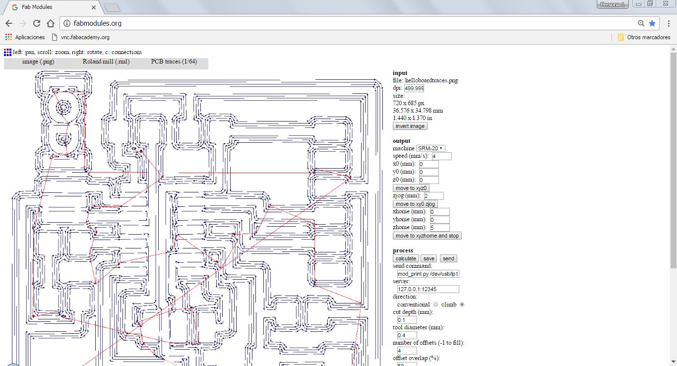
- In OUTPUT FORMAT put Roland mill (.rml)
- In PROCESS put 1/64 for traces and 1/32 for outline
- In OUTPUT on the rigt side of the window put the following values: Choose machine SRM-20, put all X Y Z to 0, put XHOME=0 YHOME=0 ZHOME=5.
- Then CALCUTE BUTTON


For milling the PCB traces:
- Put double side tape to the back of the PCB for not moving of the plataform.
- Adjust the drill 1/64.
- Set from the software manually X/Y and Z.
- Let the drill drop softly in the new X Y Z.
- Set the new X Y Z in the buttons on the right side.
- Upload the gcodes (previously done in FabModules) in the CUT button, then DELETE ALL-ADD GCODE-OUTPUT.
- Set Speed at 20% for checking the process, if its correct then put 60% for all the work.
- Press VIEW button for see if the work were correct.
- Press Z button to change the drill to 1/32 NOTE: X and Y stays do not reset it.
- Set new Z home manually.
- Press CUT and upload new gcode and press output.

For milling the PCB outline:
_Soldering and stuffing.
For soldering and stuffing this time I done a good job at once, I feel more confortable at doing it.

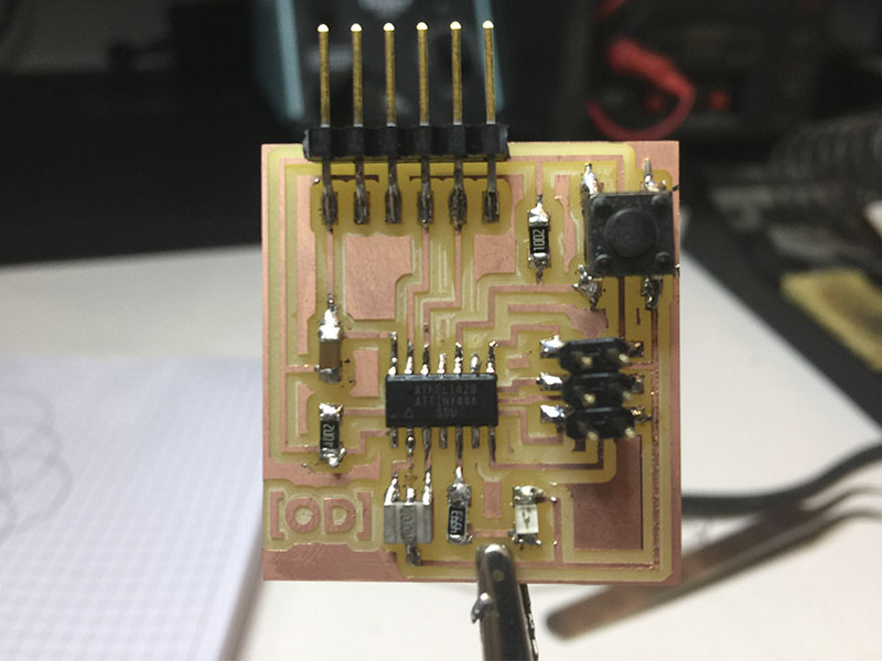
_Testing board.
For testing the board, I connected with the same motherboard that in electronics production an appeared green light at first try (all the connections were correct).
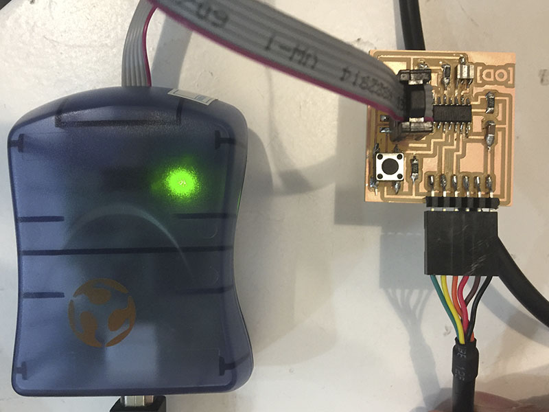
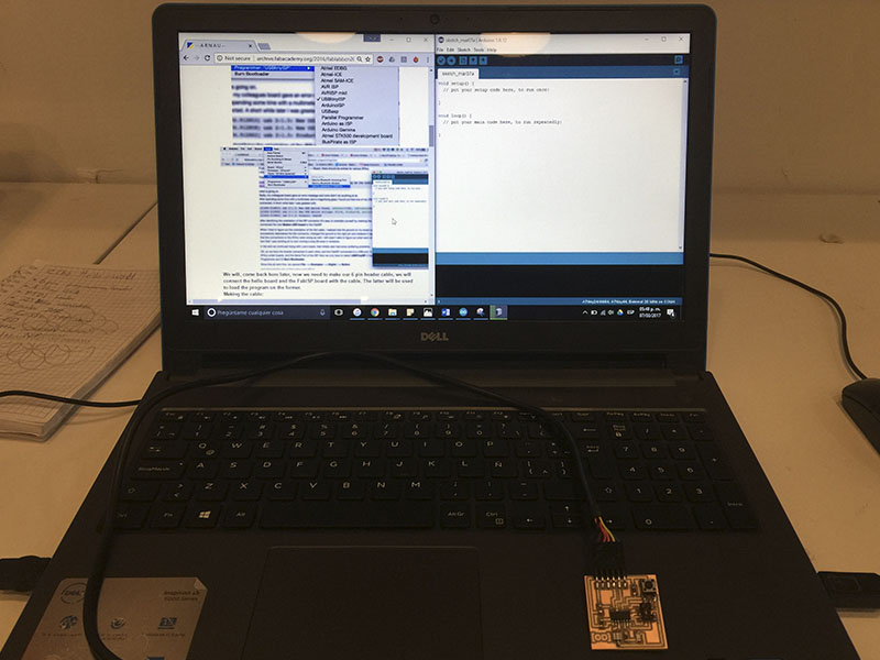
At the moment of trying to program from Arduino it appears an error in my laptop so we try with a MACbook and could program it. Later the LED do not turned on so I saw after several repairs that the 499ohms resistor was not the correct so I changed and turned on!.
_FILES
All the files for this assignment are available to download here