_Week07_COMPUTER-CONTROLLED MACHINING
_Introduction
In computer-controlled machining week we saw how you work in CNC machines knowing about equipment, materials, tools and as well as software to create the gcodes (toolpaths); we knew the advantages of creating a properly sorted file and different techniques to take advantage of everything the computer-controlled machining offers us.
_Background
Computer-controlled machining is the use of any automated tool from any CNC machine (Computer Numerical Control) in which through computer-programmed sequences; The use of any CAD software for the design of a project is passed by a CAM software that makes the manufacturing addresses in a specific material creating a toolpath making equal use of a post processor software which is loaded to the CNC machine. It is possible to specify everything in the toolpath software for the work: what type of material (dimensions, thickness), tooling, speeds and feeds, etc.
Differents Opensource projects:
Differents CNC machines:
Differents CAM softwares:
_Week Assignments
_Workflow /Step by Step

_Select Material.
There is a lot of variety of materials but for this time we only got two options:

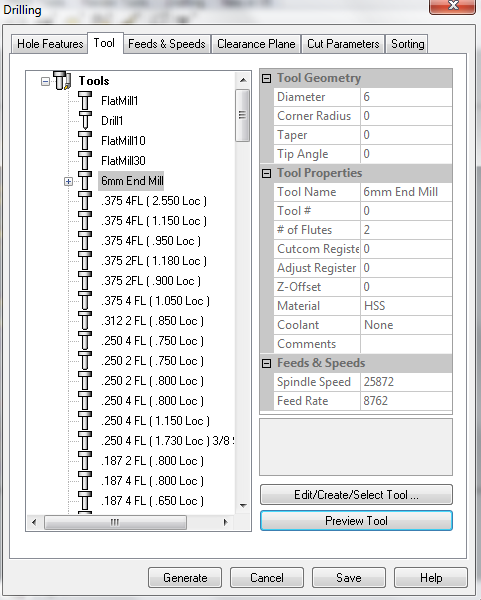
_Select tool.
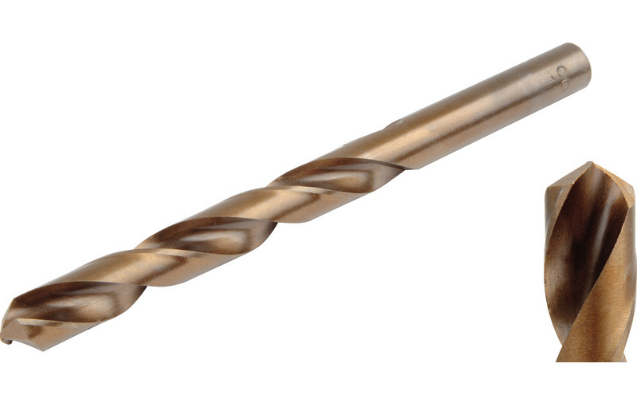
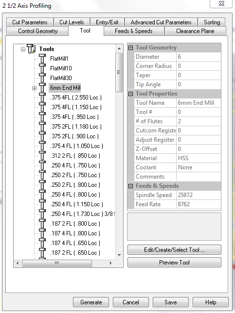
We work with the 6mm drill bit testing before with the OBS checking for the first time the software and important technical things of the head of the drill tool, how to start with the CNC machine and how to put the material sheet in the workspace.
The main difference between a drill bit and a mill bit (end mill) is the work done by each tool, in this case a drill bit performs the holes for the dogbones and performs a job down the sloth; the mill bit works to cut the sloths and remove the material horizontally or cut the necessary parts.Drill bits are usually longer, more flexible and have only two flutes, and a sharp point. Mill bits are short, hard, very sharp, with 2,3 or 4 flutes, can be flat or ball end, you can drill with them, you can use one in drill press, they're designed for cutting laterally
_Design.
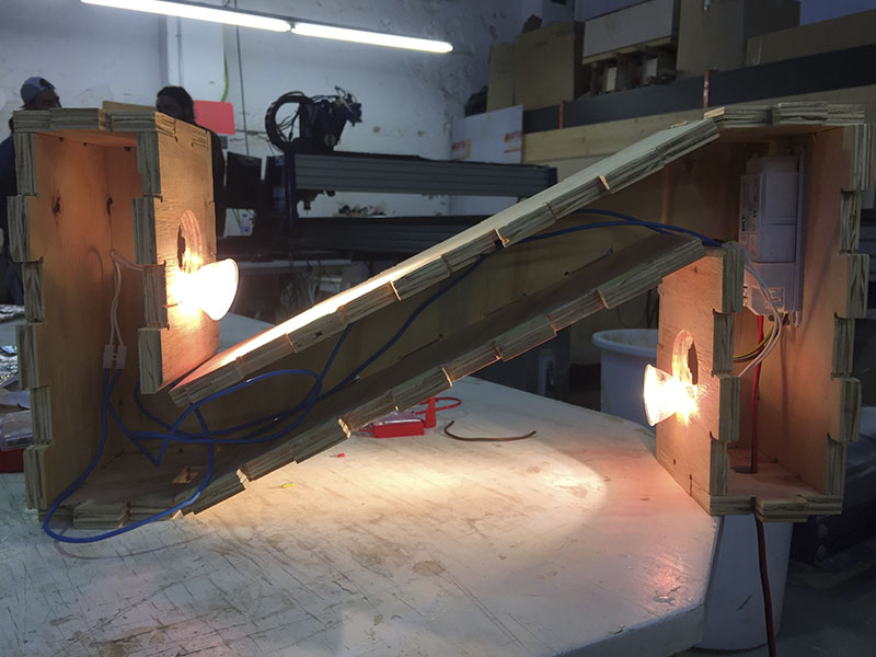
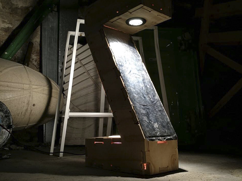
With my background in lighting design I´ve been working in a project to develop a bollard for exterior footpath which gonna bring light up (to the trees) and down(to the feet).
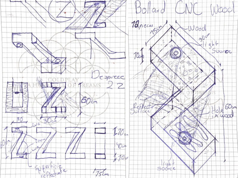
LumZ prototype have a Z design in order to bring two different angles of light having all the electrical instalation inside and two reflective surface for avoiding the glare. I started to design in Rhinoceros drawing a kind of milano wood joint for assembly all the parts but also for the diagonal surface of the "Z" i have to measure the angle correct of reflection.
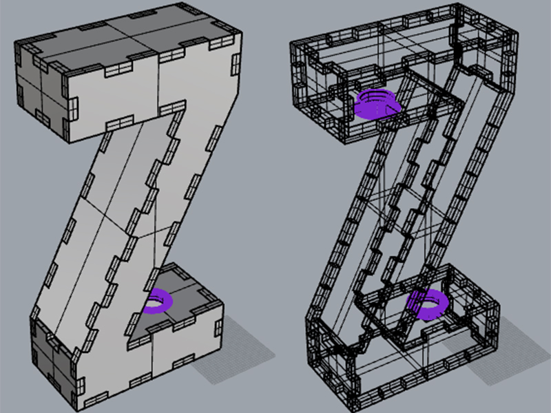
NOTE Always is helpful to assembly all the 3D model for seeing all the correct joints and have all the file ordered in layers helpful at the hour of the milling (for example one of the profiling, of the pocket, of the holes).
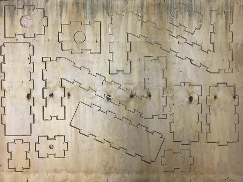
_Nesting
Always in order of avoid the waste of material and take advantage of the entire sheet of material is good to organize very well all the pieces within the space available, in my case I could arrange all the pieces in 80cm so i worked in a leftover sheet of that size. It's important also check the cleareances between each piece and the path of the drill bit across all the pieces.
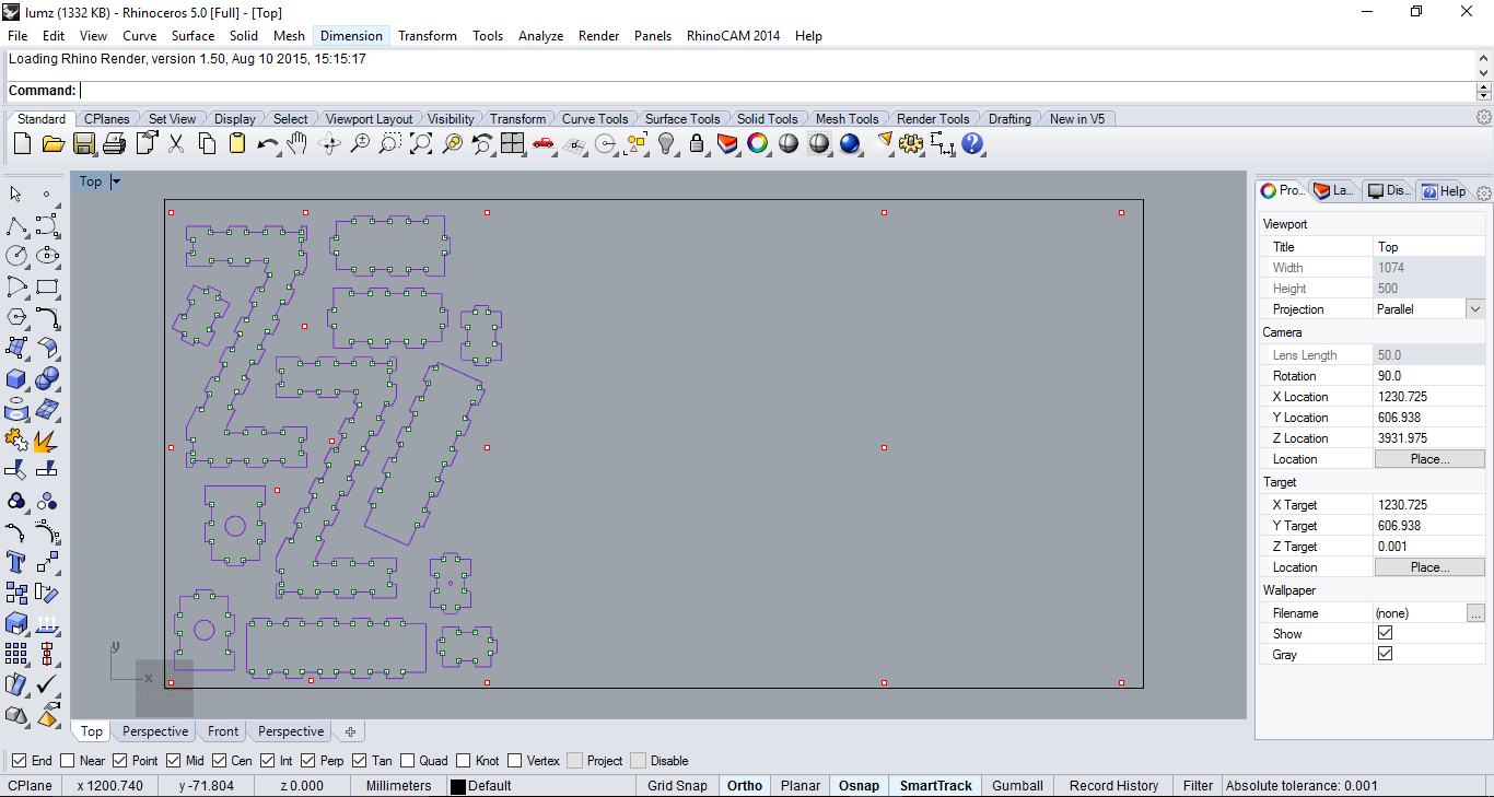
NOTE Be careful in the settlement of all the pieces and the holes (screws for fix the sheet into the bed).
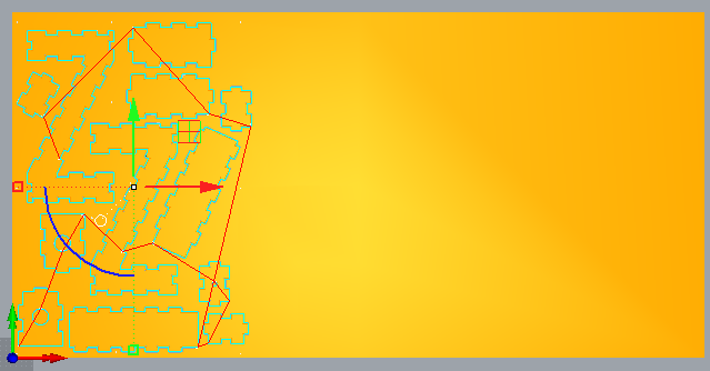
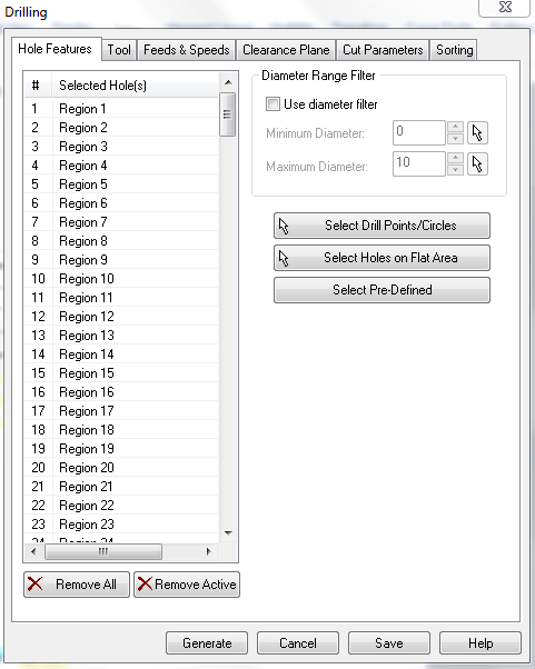
_Generate and check gcode.
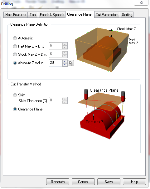
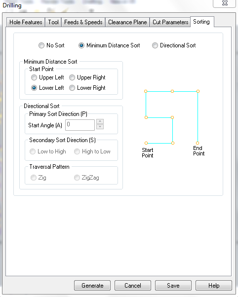
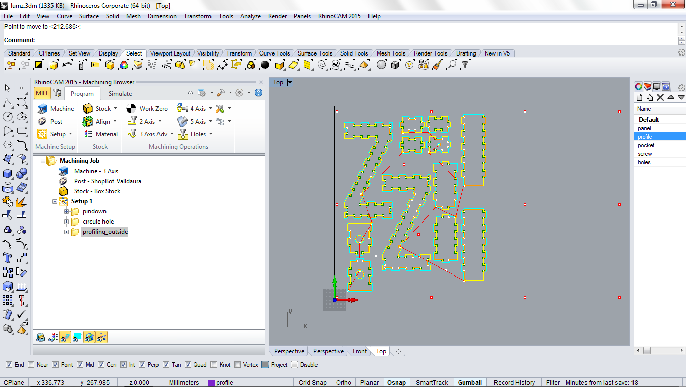
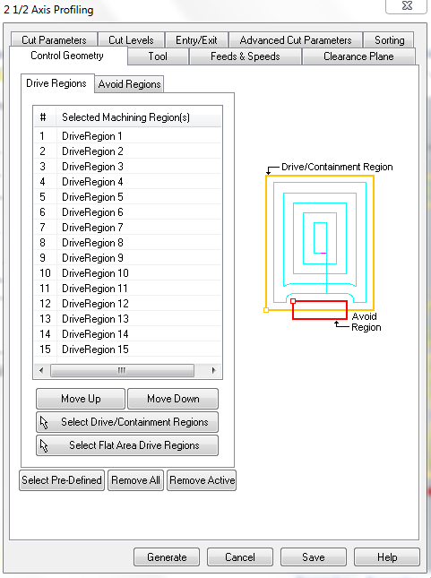
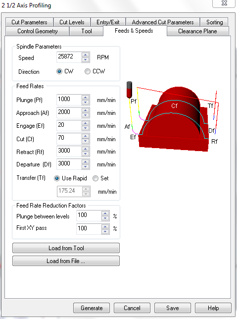
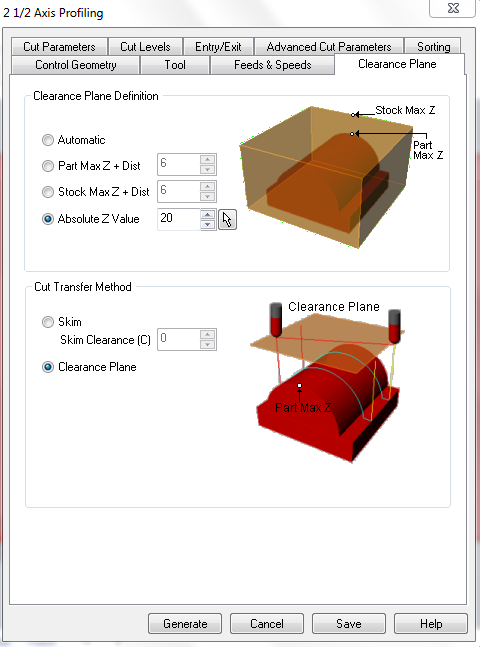
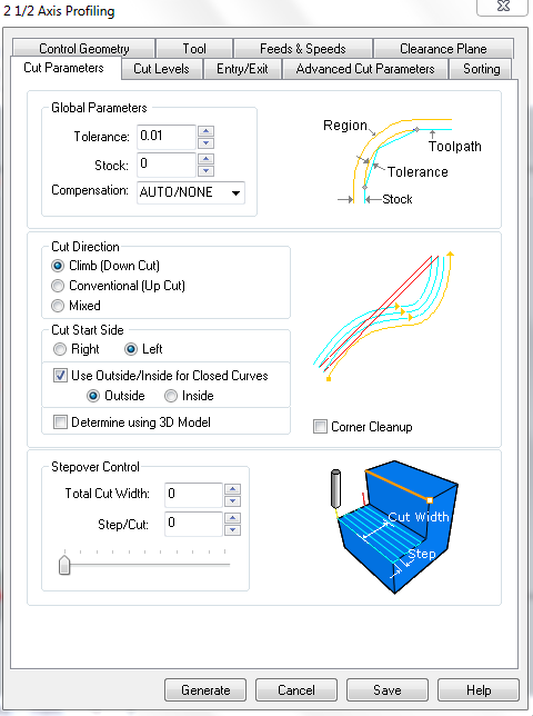
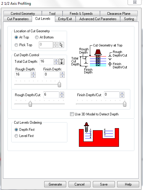
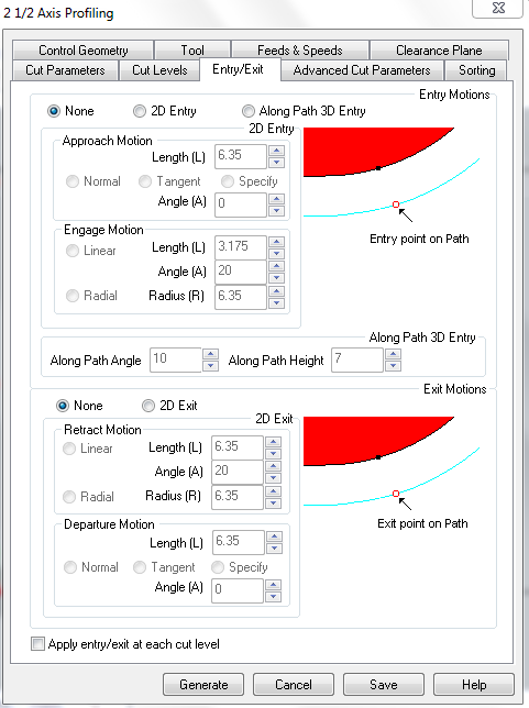
I generated the gcode in RhinoCAM in Valldaura GreenLab in order to use their Valldaura ShopBot profile which have the correct configuration of the sets of the machine for milling. I upload the profile and check each configuration in the following order:


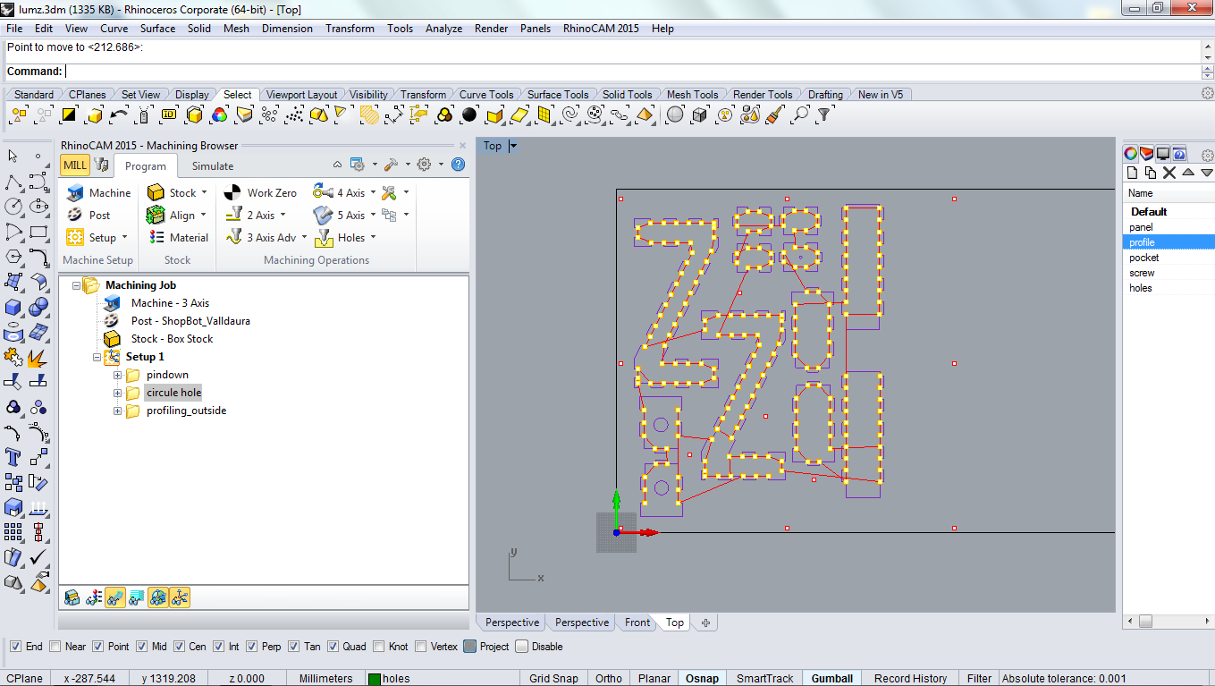


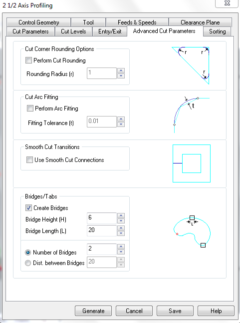
Then export the .sbp files for milling the work, first the pindown work selecting it and then the circle holes and profiling in the same file.
NOTE Generate, simulate and check the gcode if it's correct all the cleareances and cut depths. In this case I didnt have any pocket work. Check also the bridges made by the software for help the milling work.
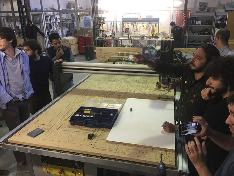
_Milling.
For the milling at first, the team encouraged us in double measure our material sheet in order to avoid problems once the cut is done, I uploaded the .sbp file of the pindown for putting the screws for fixing the sheet on the bed. Arrange the X and Y axys and then the Z axys in the middle of the sheet.


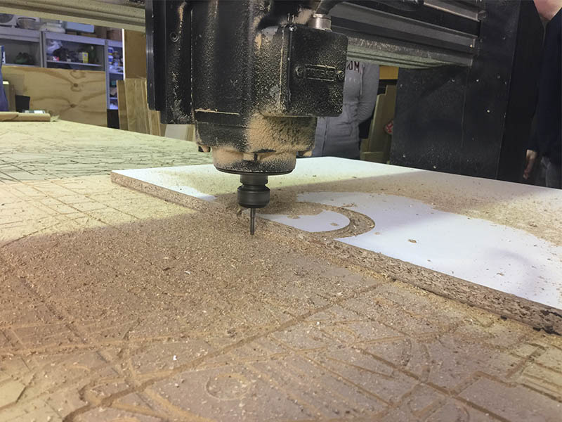
Once that is done the pindown work and the screws are in place, I reset the Z axys now that the sheet are correctly placed and flat to the bed;then I uploaded the other .sbp file for the circle holes and profiling work.

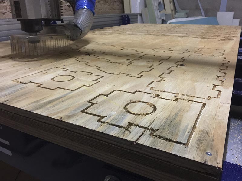
NOTE For this work it's important to wear the safety equipment, clean all the machine after using it and always keep an eye in the machine.
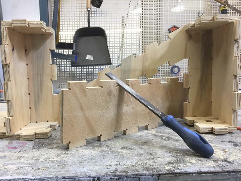
_Assembly.
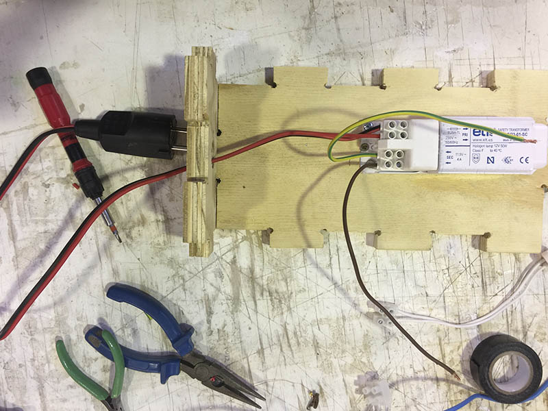
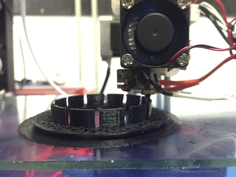
After all the milling and cleaning all the bridges and the bur of the wood, i started to connect all the electrical circuit of the lamp: 2 halogens lamps (not so efficient but cheap), a tranformer for 127V to 12V, 2 3D printed lampholders, aluminum foil and wires.


_Final review.
Things to correct after this exercise:
_FILES
All the files for this assignment are available to download here