_Week16_INTERFACE AND APPLICATION PROGRAMMING
_Introduction
During this week I continued working with the wifi module ESP 01 using to create the interface with the inputs and outputs that I require for my final project, since this same module but a more advanced version is the one I will use to control the boards in my final project . The assignment focuses on being able to remotely control (in any of several ways) some inputs or outputs from another device.
_Background
Application program interface (API) is a set of routines, protocols, and tools for building software applications. An API specifies how software components should interact. Additionally, APIs are used when programming graphical user interface (GUI) components. A good API makes it easier to develop a program by providing all the building blocks. A programmer then puts the blocks together.
Useful links:
_Week Assignments
_Workflow /Step by Step
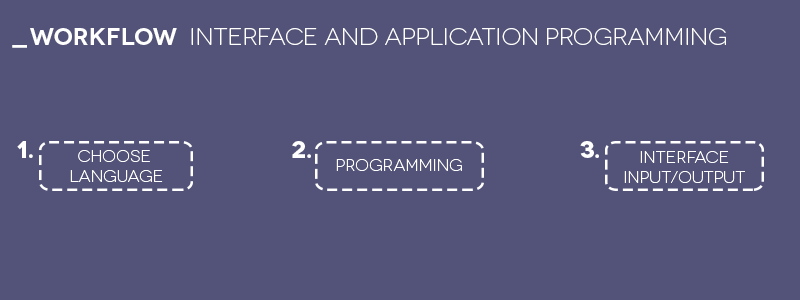
_Choose language.
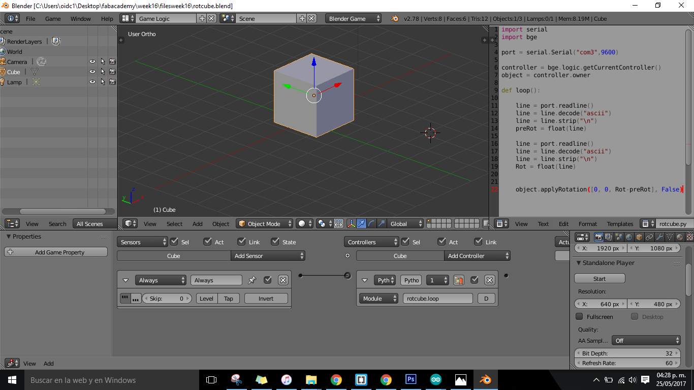
Starting with this tutorial for knowing differents ways for intefacing applications:
import serial
import bge

port = serial.Serial("com3",9600)

controller = bge.logic.getCurrentController()
object = controller.owner

def loop():

    line = port.readline()
    line = line.decode("ascii")
    line = line.strip("\n")
    preRot = float(line)

    line = port.readline()
    line = line.decode("ascii")
    line = line.strip("\n")
    Rot = float(line)


    object.applyRotation([0, 0, Rot-preRot], False)
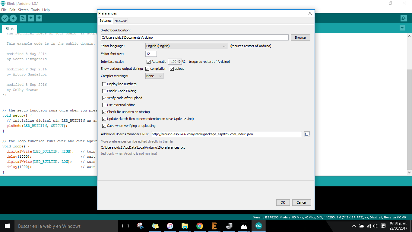
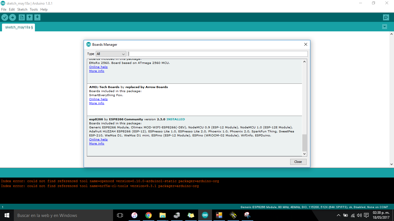
After this I continued working with the ESP 01 that it was working last week with the firmware that comes from fabric responding to the AT commands normally, but seeing a several tutorials for interfacing somehow the module with some inputs/outputs I have to flash again in order to create a web server for the interface. So I worked with the ESPlorer for ESP8266 and with Arduino IDE for doing this assignment.
_Programming.
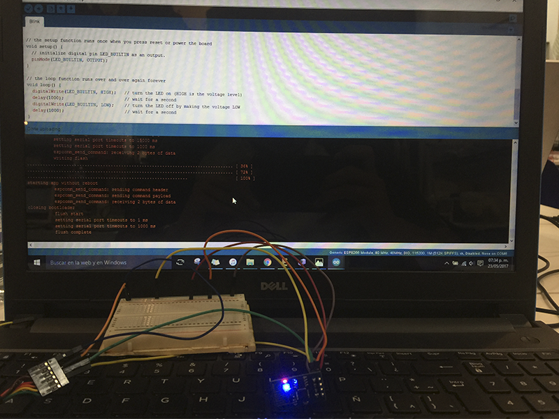
I disoldered the ESP01 from my last board in order to reflash the module because there are boot modes for flash/program/use the ESP01, also differents ways to do it (with the nodemcu-devkit, with the Arduino UNO or with the FTDI cable).
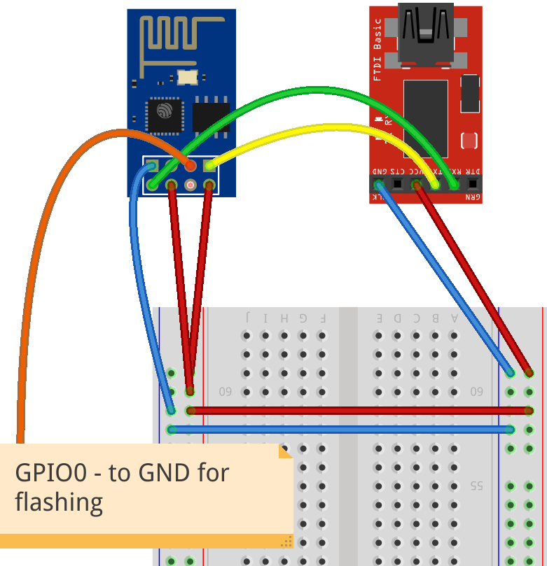
Useful links for flashing the module:
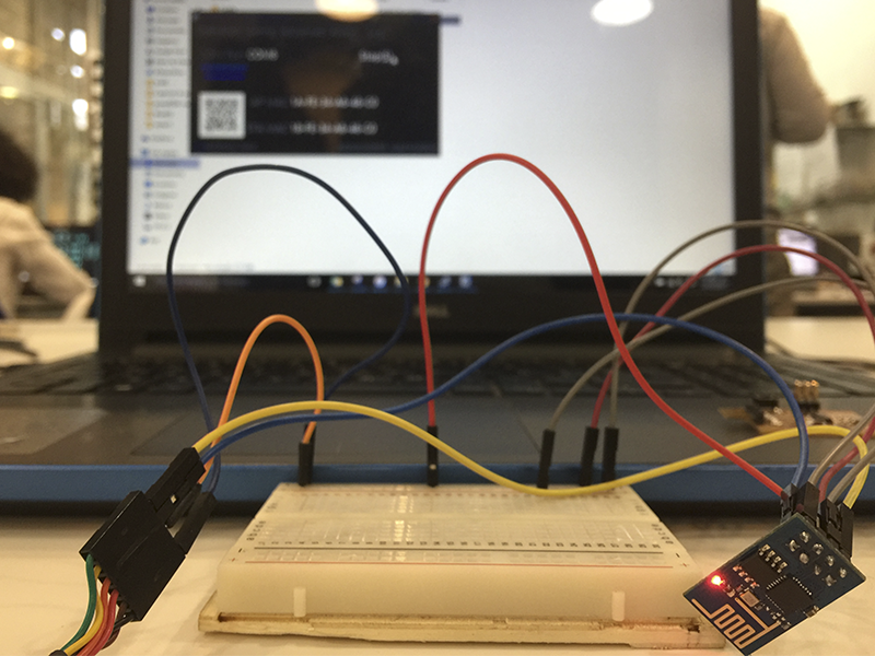
After seeing a lot of tutorials for how to do the circuit I get so confused, the module worked like this:
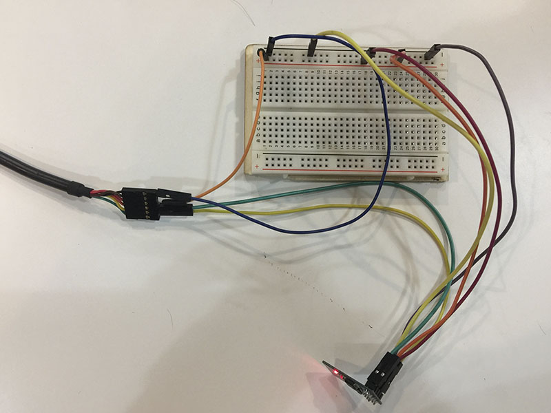
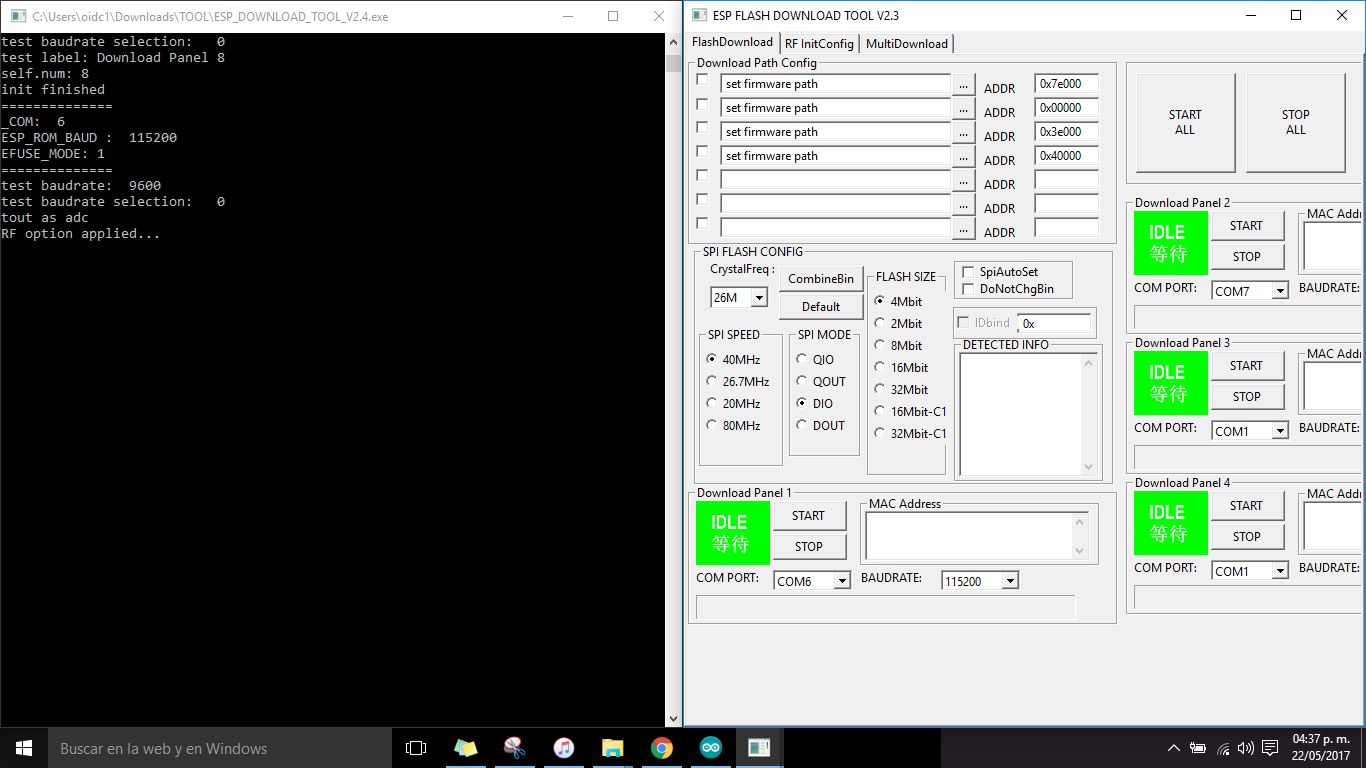
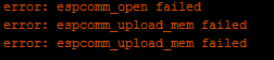
First time I tried with the ESP flash tool, the flashing was correct the firmware was updated and still working with AT commands but I was no able to upload a sketch to the ESP 01 it appear an error on the Arduino IDE that means that the module was not correctly communicating.
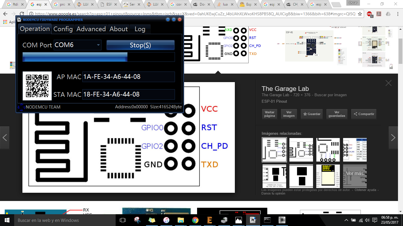
Next I tried with the NodeMCU flasher tool
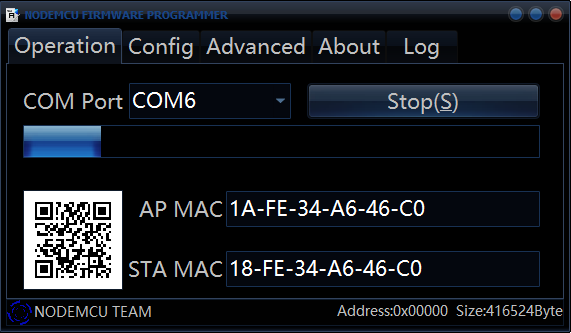
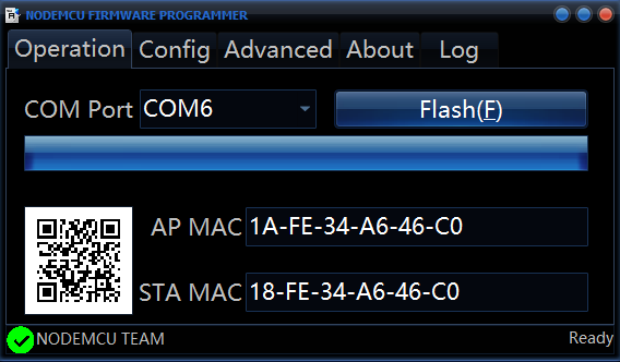 And it worked but there was a mistake... I tried to connect with the ESPlorer the module and... nothing happened.
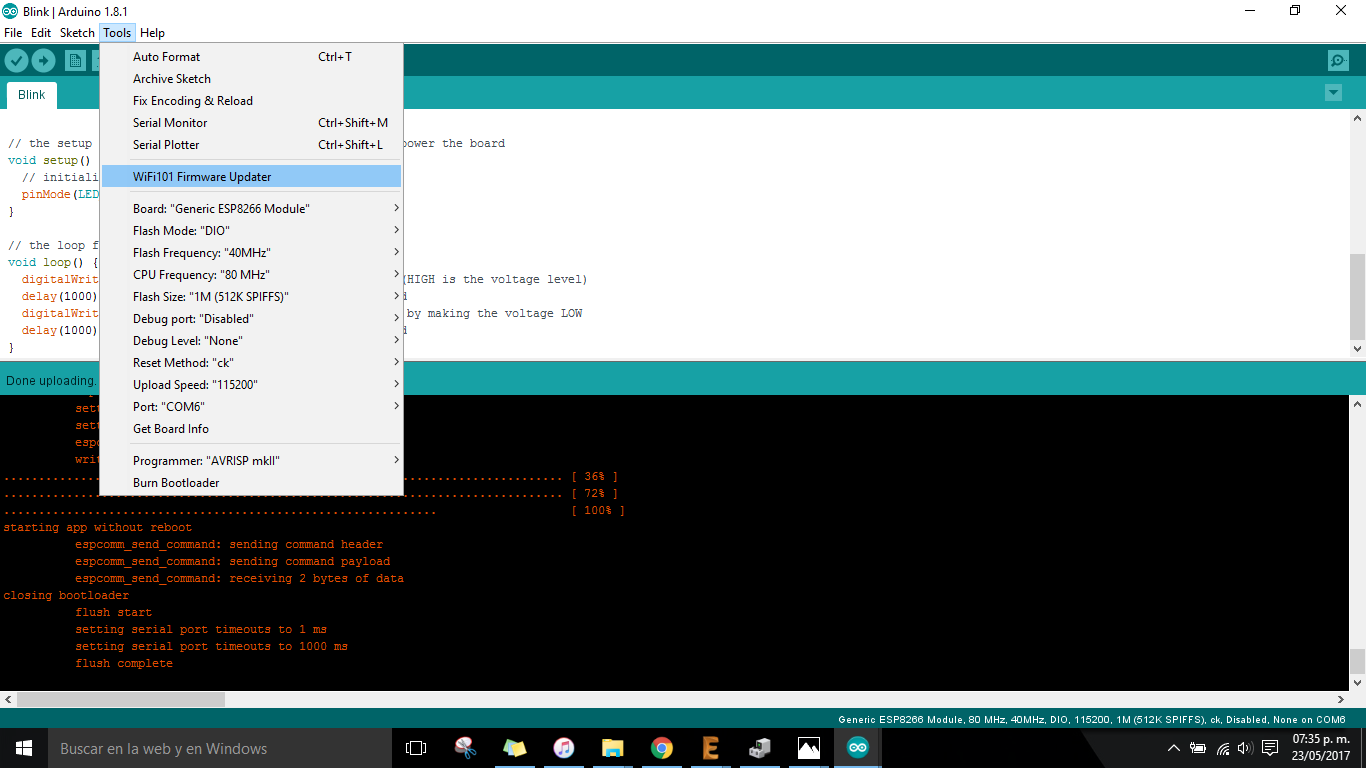
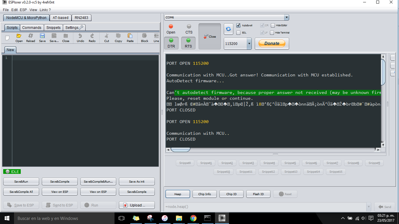 But then Victor help me (a lot) to get it work and understand why this doesnt work we tried to reflash the module but getting no success! After several hours of work we discover WHY! the module was flashed with the incorrect flashsize and baurate so the module stay in a loop for START-RESET-START-RESET when I tried to program it.
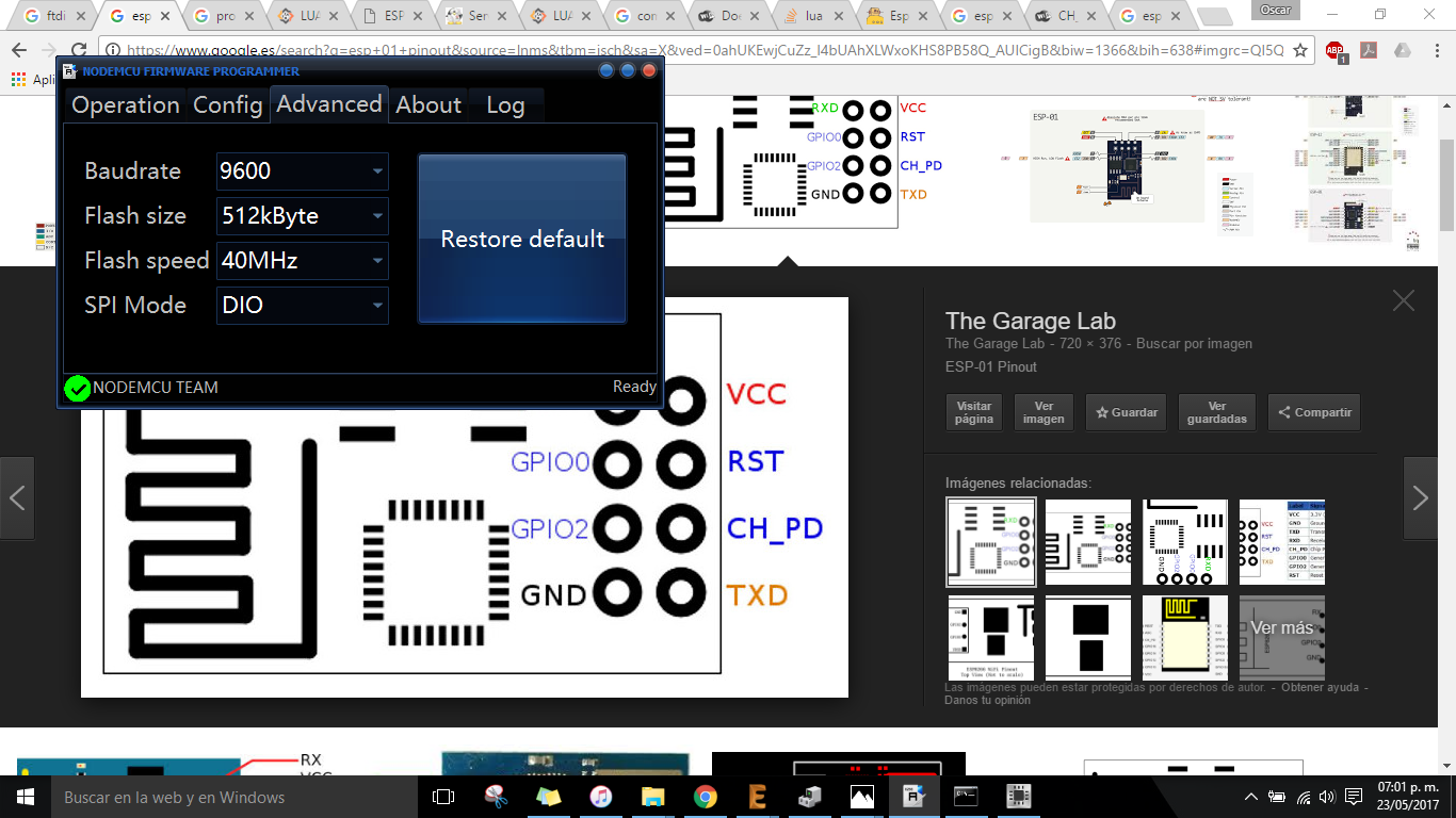
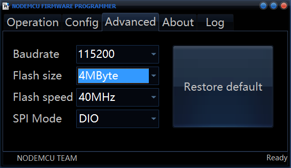 So then I continued my work with a new one ( no remedy :( ) now changing correctly the advanced configurations and keeping the same circuit as the beginning.
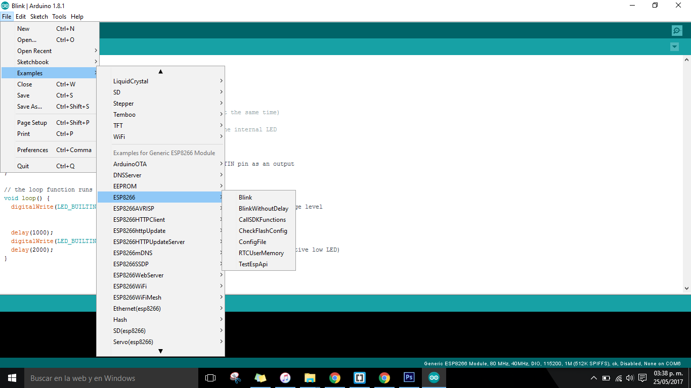
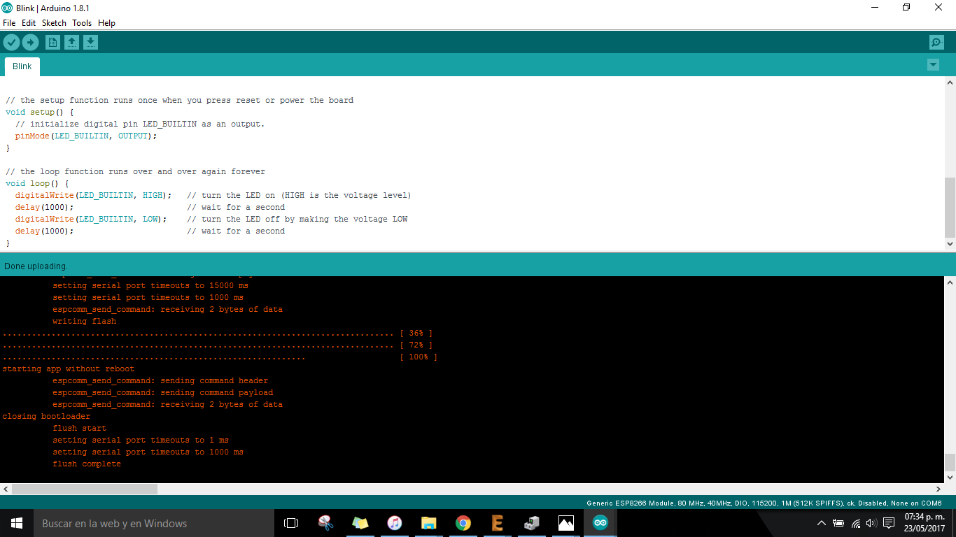
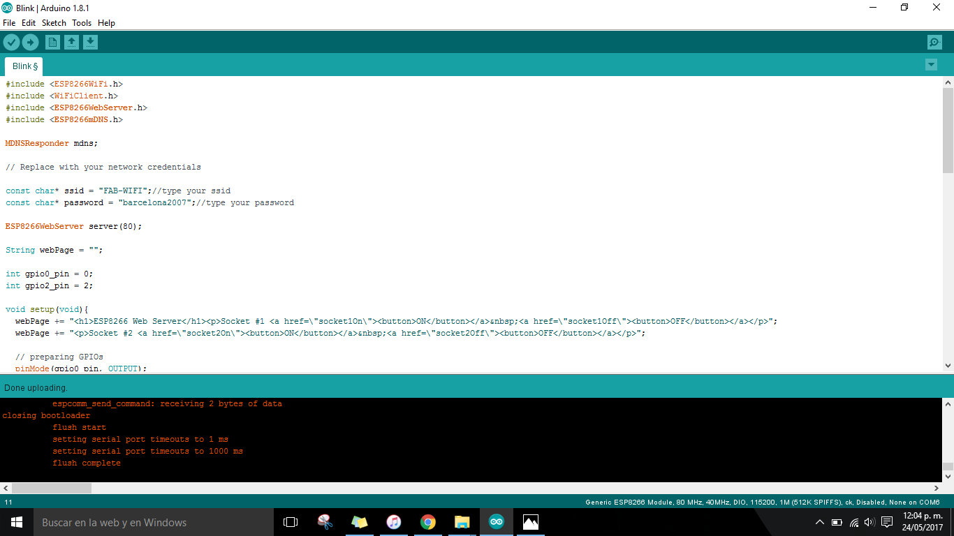
Then working on the Arduino IDE for making the communication and uploading a sketch to the ESP 01:
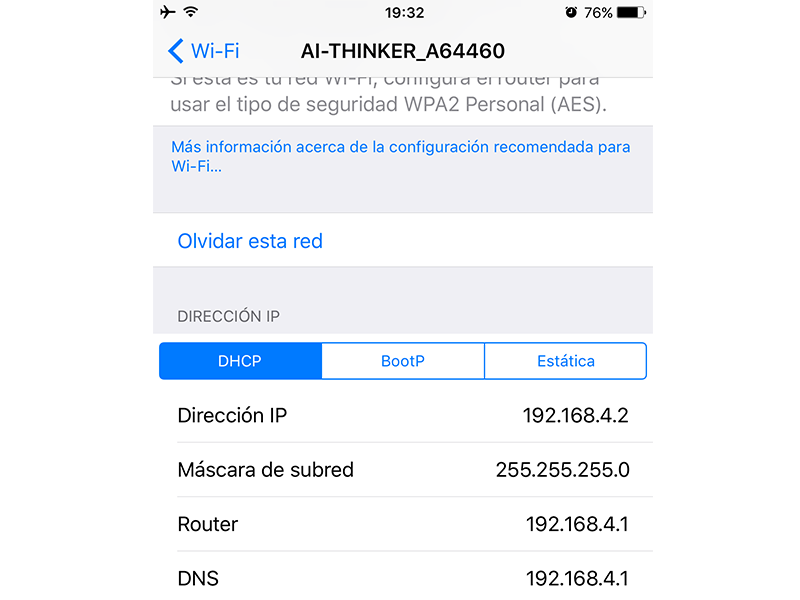
 And creates its own IP
_Interface INPUT/OUTPUT.
Now it's time to interface the module with some inputs and outputs (so useful for my final project), I started with some easy tutorials using a webpage for showing what was happening with the components.
Useful tutorials for starting:
IMPORTANT NOTE
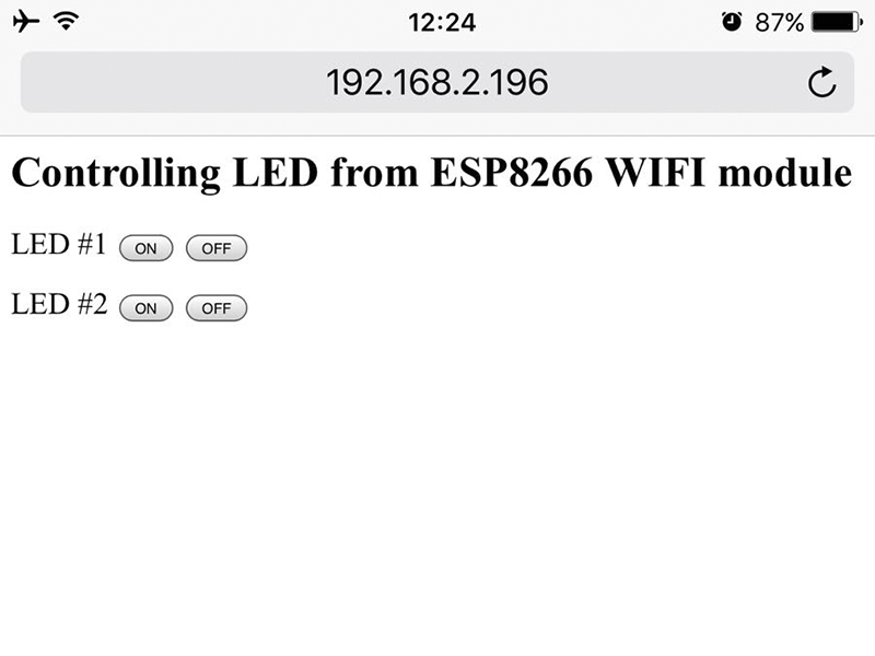
Following the ESP web server I program it the module for creating a webpage that could be edited from the Arduino code, showing an interface for controlling both LED in the circuit.
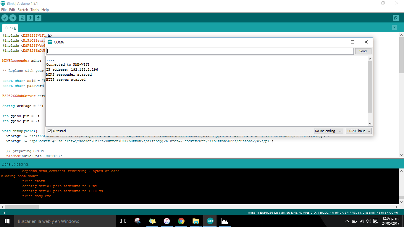
Copy and paste the IP adress printed on the serial of Arduino in the browser for seeing the webpage with the buttons to control the LED's.
Afterwards, I interface my own board that I made with a RGB LED for controlling the color by creating buttons like the code used before just changing the name and just getting the VCC and the GND from the breadboard.
_FILES
All the files for this assignment are available to download here