Final Banner
My Final Presentation Video
3D Model of Maze Solving Robot
As being a person from the computer science department I always think projects in the direction where computer is involved in solving the real time problems. So for this Fab Academy I also wanted to create some thing like that.
Since childhood I appreciate the field of robotics, as being here is a chance for me to enhance my experties, I would like to work on it.
I like to create a Line Following Robot which can solve Mazes.
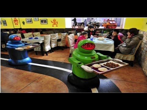
Well nowadays Line Following robot is getting more and more used in the industry and real life, such as Industry Assemblies, conveyere belts, restaurants and many other places. So I wanted to make such a thing as well.
My main field of interest for this project is Hospitals where the passing of reports and medicines is done by the personell so instead of that its better for the robots to remember the shortest paths and move efficiently to pass things.
The basic Robot Lookup
Being a computer scientist I am very excited about robotics, as it is a multi-disciplinary task, involving Electrical, Electronic and Mechanical Designing and requires sophisticated computer algorithms to pull all these things together.
For this project I will be deisigning a complete system bottom up. The major steps of this project will include
To start work on proejct early than planned, I started making my week tasks based on the FINAL PROJECT. In Output Assignment I created the double motor circuit which will be used to move the car. While creating the circuit i found that I cannot make the circuit on single layer so I had to put one jumper to resolve this issue.
Double Motor Driving Board reference
After this I went through all the process of milling and soldering and completed my circuit, the process is deeply explained in the weekly assignment
Double Motor Driving Board Soldered
Well after a few tests I dropped this board and needed a replacement, as this board has the memory issue. Just after the installation of motor code the memory was 87% full. So I just found a replacement of it. My friend was working on the Arduino Leonardo board, so I asked him to help me build one also and after his help I made this board.
Main Board Traces
Bill of materials
Soldering this circuit was a little issue, as the pads were to small and sometimes I combined a couple of pins together. Thankfully, I found some Magnetic Flux Solution, and then it was much easier to solder the board.
After Soldering
The next baord which I milled was obviously the IR sensor board, which I want to use in my project. I found the reference board on Sparkfun and then created a relatively same board for my own project. This board requires QRE1113 IR reflectance sensor. This sensor can read the IR reflective value.
IR Reflectance Sensor
IR Reflecance sensor, well due to its smaller size, it was a little difficult to mill and solder.
IR Reflectance Sensor Soldered
After my previous motor driving circuit didn't worked so this time I thought to work in separate parts, and I chose the motor driving circuit to make it separate from my microcontroller.
Motor Driving Circuit
Motor Driving Circuit Soldered
Power Controller Board
Power Controller Board Soldered
Files available to download
I was focusing on multiple parts which can be 3D printed, so I went to make the auxillary parts like wheels and ballcaster based on 3D print.
I started off with working on Fusion 360 as I had best hands on practice on this one.
3D Wheel Design Outlines
After Applying 360 Revolve
Decorating wheel with removing the extra parts and only retaining supports
Making Axle Motor Support Place
Body for holding the model together and PCB
Complete Body with Ballcaster attached as well
After the models were ready I went for the 3D printing, I started off with the printing of the wheels, and the results quite better than even expected.
3D Printed Wheels
Files available to download
I have designed the model for the lasercut in Rhino to cut, well the process of lasercutting is same which I explained in Laser Cutting Assignment, I just made one file and then sent them for the cut
Laser Cut Model
LaserCut Process
Laser Cut Result
List of parts of lasercut needed for project
Files available to download
For coding part I searched internet and found a relatively good help from here
I used 7 Line Reflectance sensors to read the output of the color of the line. It was a basically a little tricky. I have total 7 pins so the number of possible combos was also a little bigger.
I divided my sensors in 5 in front and 2 at the rear. Front sensors will help in finding the path and the rear sensors will help to remember the paths.
Here are the possible paths which my board can detect for a straight line. As I have used the black tape, its width was not bigger than to be detected by 2 sensors.
Possible Paths
LF Robots decision at different points of junctions
Then I created an array of the sensors in front to keep track of them
Declaring the pins for the input
Creating an array
This is the main code for solving the path and remembering them
Files available to download
I have already made the Project Development Plan here
Well as I already have gotten all the components, now it was time to assemble all the parts.
Assebmling
Final Look after complete assembling
After the assembling of parts now it was time of testing the movement.
Assebmling
After a few changes I finally made a working demo
Working Demo