Muhammad Asim Samejo
Mechanical Design
The week we have group assignment. The objecive of this assignment is:
- Design a machine (mechanism+automation), including the end effector.
- Duild the passive parts and operate it manually.
- Document the group project and your individual contribution.
For this assignment our group consists of
| Tomas Martin Agudo | Sohail Ahmed Soomro | Nisar Ahmed Siddiqui | Fida Hussain Memon | Muhammad Asim Ali |
|---|
Our objective for Mechanical and Machine Design assignment is to design a Wally style 3D printer illustrated below.
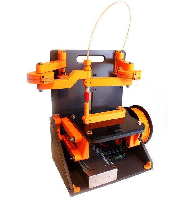
Wally is a variant of reprap 3D printers which belong to Selective Compliance Assembly Robot Arm (SCARA) family.
The beauty of this project is that this project can be readily printed with a printer and (and hence machine making machine). Printing Wally is no small task. The printed parts take almost 1kg of PLA and 40-45 hours to print a complete set. Nicholas Seward recommends PLA printed at a 0.3mm layer height and 15% infill with 3 perimeters.
Some of the technical specifications of the intended design are pasted here for reference.
| Specification | Value |
|---|---|
SCARA is a diversion from the linear family of 3D printers. A good introduction is available here . The salient features of this design include elimination of driving belts, threaded rods (which require lubrications).
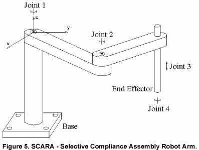
This is graphical illustration of a SCARA robotic arm. As evident from the drawing the robot consists of more than 3 joints. The first motor (joint 1) rototes about its axis, the second motor (located at joint 2) can extend the range of the machine allowing it to position itself to an exact (x,y) coordinates. The position of end effector can be changed through joint 3.
Wally is a subtle (simple yet delicate) variation of scara printer models. In contrast to SCARA where motor is mounted at a joint connecting first and second segment of the arm, the motors are mounted at the frame.
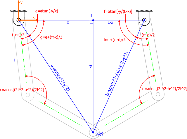
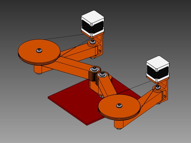
Wally places the stepper motors on the walls of the frame to reduce the wieght and allow the arm to move at faster speeds. The position of the arms is adjustable through fishing line drive belt as illustrated below.
My contribution to the project
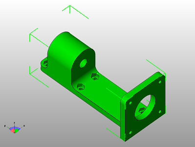
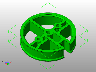
The mechanical assembly of xy movement axis required the following components.
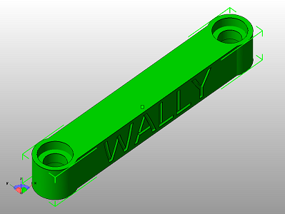 |
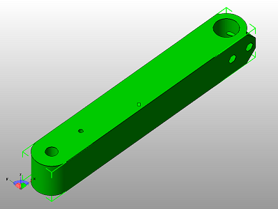 |
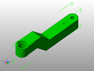 |
|---|---|---|
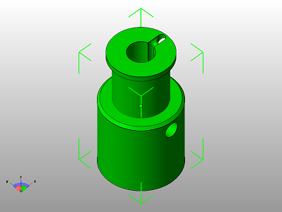 |
 |
 |
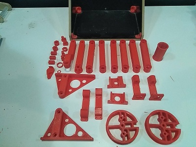
The .stl source files are available here .
All the components were printed using reprap printers available in our lab.
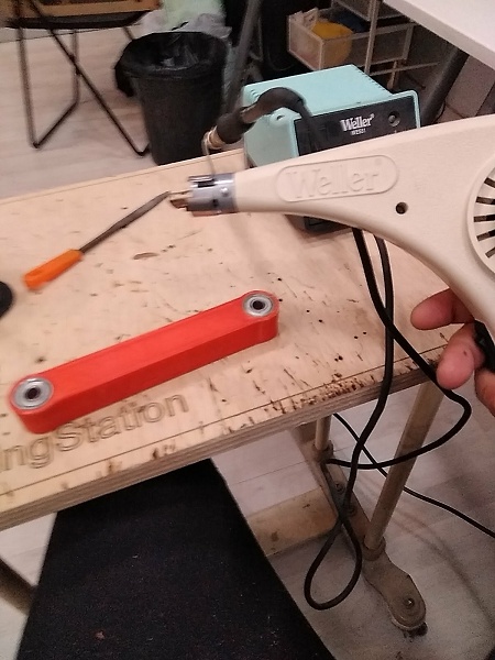
Inserting bearings where necessary.
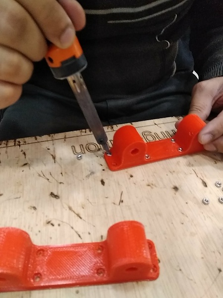
Inserting screws in the assembly.
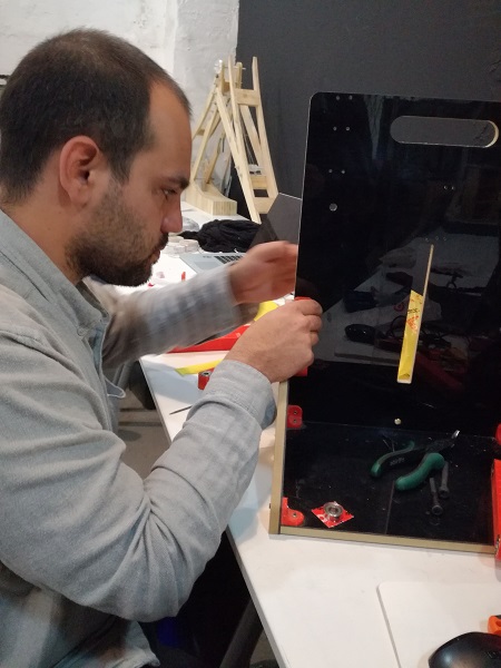
Time spent assembling.
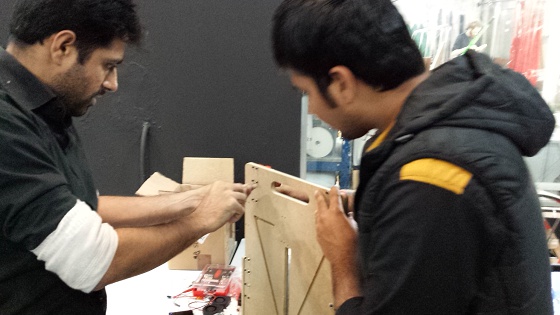
Yet more time spent assembling.
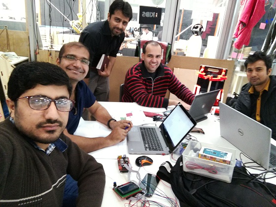
Finally, model assembled and a happy team.
A comprehensive documentation of this group assignment is available here

This work is licensed under a Creative Commons Attribution-ShareAlike 4.0 International License
Copyright © 2017 Muhammad Asim Ali
This work is licensed under a Creative Commons Attribution-ShareAlike 4.0 International License
Copyright © 2017 Muhammad Asim Ali