Week 20:Final Project
Final Presentation
video
Explain and summerise all steps of the project
Cost of the project
Licence
Acknowledgements
Final Presentation
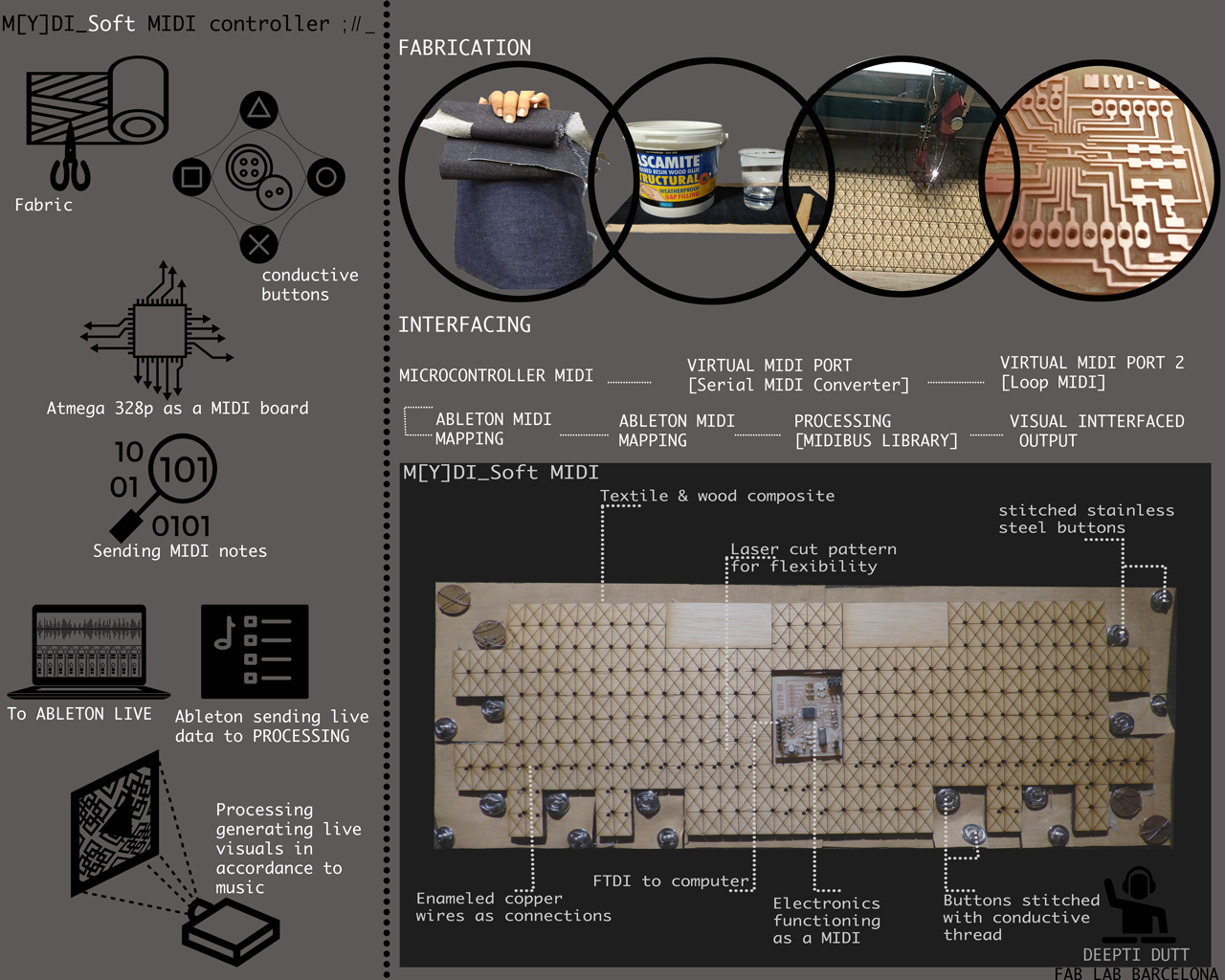
This is for my final project.But for my project, I need a constant connection with the computer, as a MIDI controller constantly sends signals from an analogue input or buttons so to say to the computer which turns the signal to digital in order to give an out put of sound or graphics. This happens in real time, as every time a key/button or basically an electrical signal is passed to the board which sends signals to the software in order to generate an out put.
For this reason I added an extra FTDI pin connection to my board and MODIFIED my board. Also, in the Satshakit, in order to program the board, the pins needed, i.e., MOSI, MISO, SCK, RST, VCC and GND are distributed randomly along the board as they are also used as pins that can be connected as input/output pins. So, I decided to also have the pins needed to program to be grouped together, just like in our Fab ISP.So that, its easier to recognise and connect , inorder to program it.
To start off, First, I understood the parts of the satsha kit, and started designing my own board on Eagle software

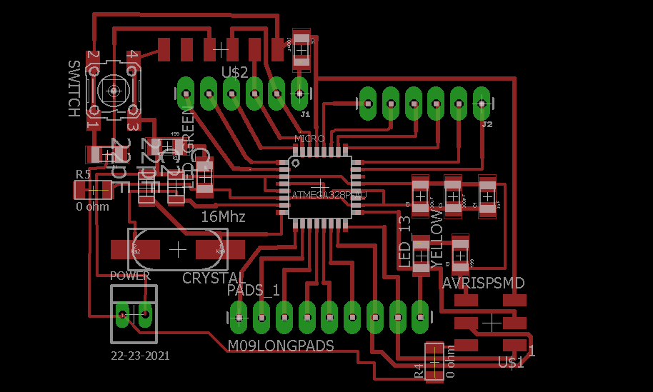
Once the board was designed, I exported the files from eagle to photoshop as an .eps file so that i could make the .png file to be loaded on fab modules.Here in this image, I am showing the traces file. But I made seperate files for the holes and the outline.
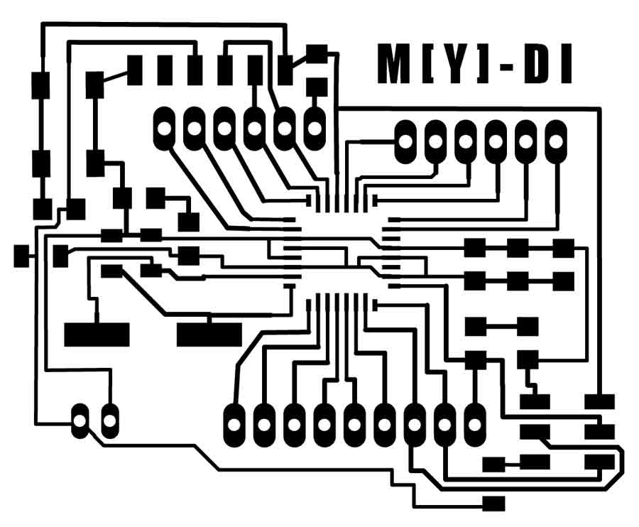
For the milling process of the traces, I set the offset on fab modules for my board as -1, I wanted clean traces with no extra materials but the lines of the board, as this was for my final project. And, I want to keep the board open so it can be seen as oppposed to being hidden.
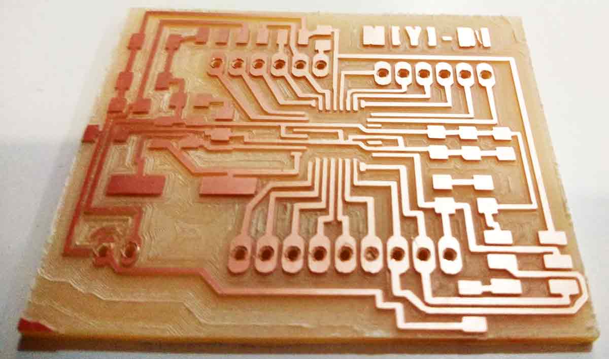
THis is how my board looked when I was done with milling the board on the roland Mill, I was quite happy with the end result. For the next part, was abput soldering all the components.The components needed were:
AtMega 328P
Crystal 16MHZ
Capacitor 22pf
Resistor 10k
Capacitor 100nf
Capacitor 1uf
Capacitor 10uf
Pin headers
Once i soldered the components, this is how the board looked.

The next step, was to program the board. One important note to be made here is, When I tried to program it with a commercial programmer, like the AVR ISP , it kept giving me a "fuse lock" error.Then I tried to program it with the Fab Isp and followed the instructions on the link of the webpage mentioned at the beggining of this page, there was no fuse lock error when I programmed it with the Fab ISP.This took quite a while to figure out that the problem was not with my board but it was due to the commercial programmer that it was not getting programmed.Once I bootloaded it as an Arduino, I uploaded the blink sketch to see if i works, and it did!

Using conductive textile buttons as Input device sensors
For my Input devices assignement, I wanted to use the board that i designed for my output devices assignement in week 10.The satsha kit use the ATMEGA 328P microcontroller. I read the data sheet of the ATMEGA 328P, and understood what each pin does.This Data sheet gives all the details of the atmega328p microcontroller. Also, This pin out diagram i svery helpful.

What happens with the satsha kit is that it uses all the pins of the microcontroller to give maximum number of piuns that can be programmed for input/output.In theory, The atmega 328 p has the same analog and digital pins an the arduino board , A0 to A5 analog pins and Pin 1 to pin 13 dor digital pins, whcih include the RST and SCK. But in the satsha kit,the Analog pins are from A0 to A7 and 16 digital pins which can be used for inputs and outputs.The schematic id n the week 10, output devices and there it can be seen that the number of pins are more than a normal arduino.For my board, I was not using the A6 and A7 analogue pins as I did not need them for my project.
The next part was hand crafting my input device sensor. For my Final project since I want to make a SOFT MIDI controller with tetiles, In this assignmentr , I eill be using the buttons used in textiles and fabrics as my input sensor. The bittons are conductive and hence the give a value when connected to the board.
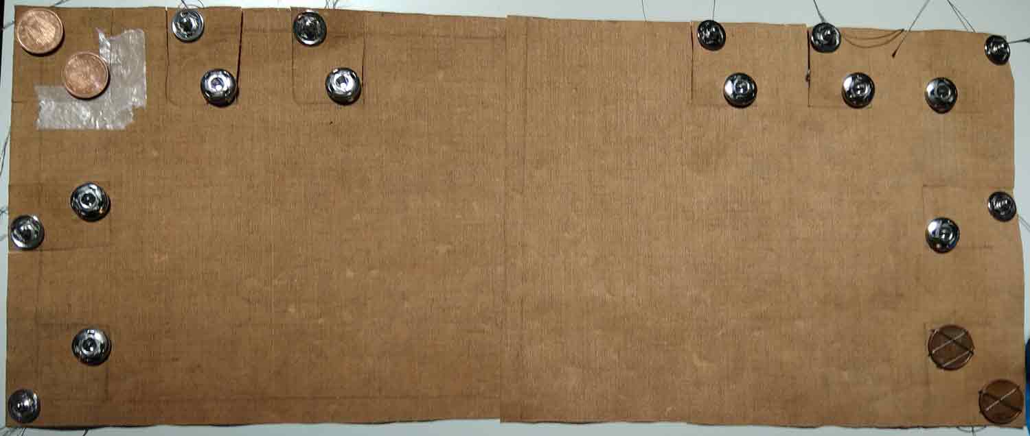
The materials needed were, conductive simple steel buttons, conductive thread, and the textile I was going to stitch the buttons on.

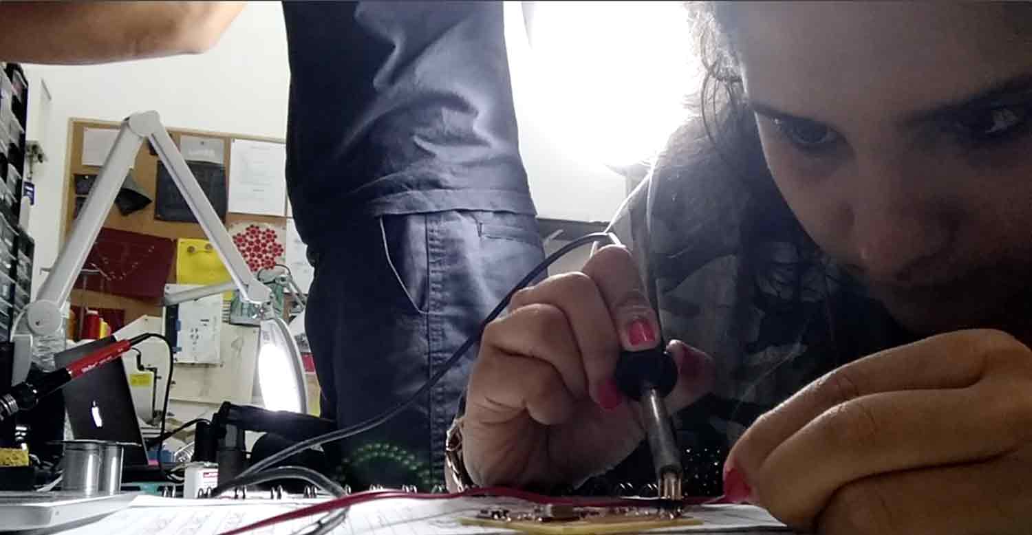
Once I assembled all the materials, the next step was to start stitching it. I stitched each button by hand using conductive thread. I had an idea about the number of buttons I want to use, so, I stitched 10 pairs of buttons. So, One button becomes the GND of the circuit and the other pair of the button goes to the pins in the board. So all the GND part of the button pairs are connected with the same conductive thread while stitching and the other button in the pair is stitched as an individual entity to connect to the board using enameled copper wires.

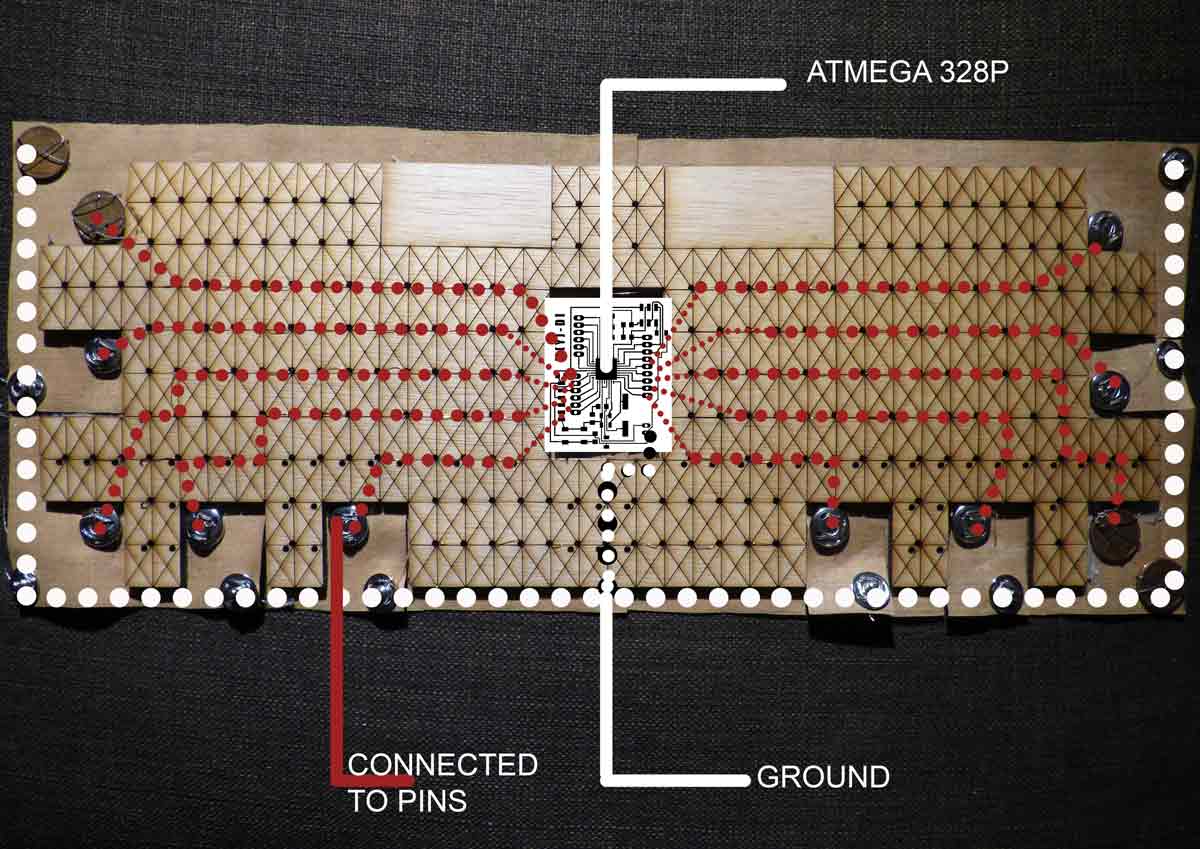
This image shows a schematic of how the buttons are connected to the satsha kit turned to MIDI controller board
In this video, you can see the process of me sewing all the connections as shown in the schematic image above and testing for its conductivity after stitching it together.
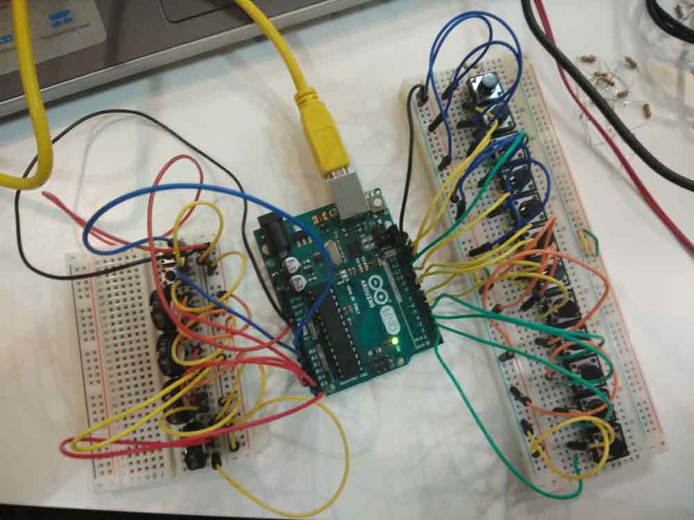
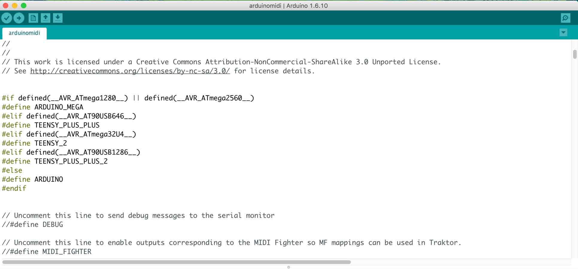
Before trying it with my board, I tried the script with an arduino and tactile buttons on a bread board, in order to test the arduino code and see if its working. More about the code and how i made it work is in the project development week. This arduino code that I am using works only on Arduino IDE 1.6 and I know this because I tried to make it work on the latest versions of the IDE and older, but this version is the only one compatible with my code. It convers each anolog and digital pin into a MIDI note. And with "noteOn" and "noteOff"commands, it works exactly like a MIDI Device.
What essential happens in a MIDI controller , well a MIDI is a Musical Instrument Digital Interface, so this Micro controller helps interface and communicate with a digital music tool or electronic intrument with analogue inputs.Lets understand what is happening in the code, breifly. In here, The first step, we define arduino, as the board/controller we are using as the MIDI controller board.
Then, we define the parts of the MIDI device which helps to make the music, that is, the MIDI notes, the reverb, chorous, controls, etc.,

The next part of the code defines the MIDI channel and notes in accordance to the pins.
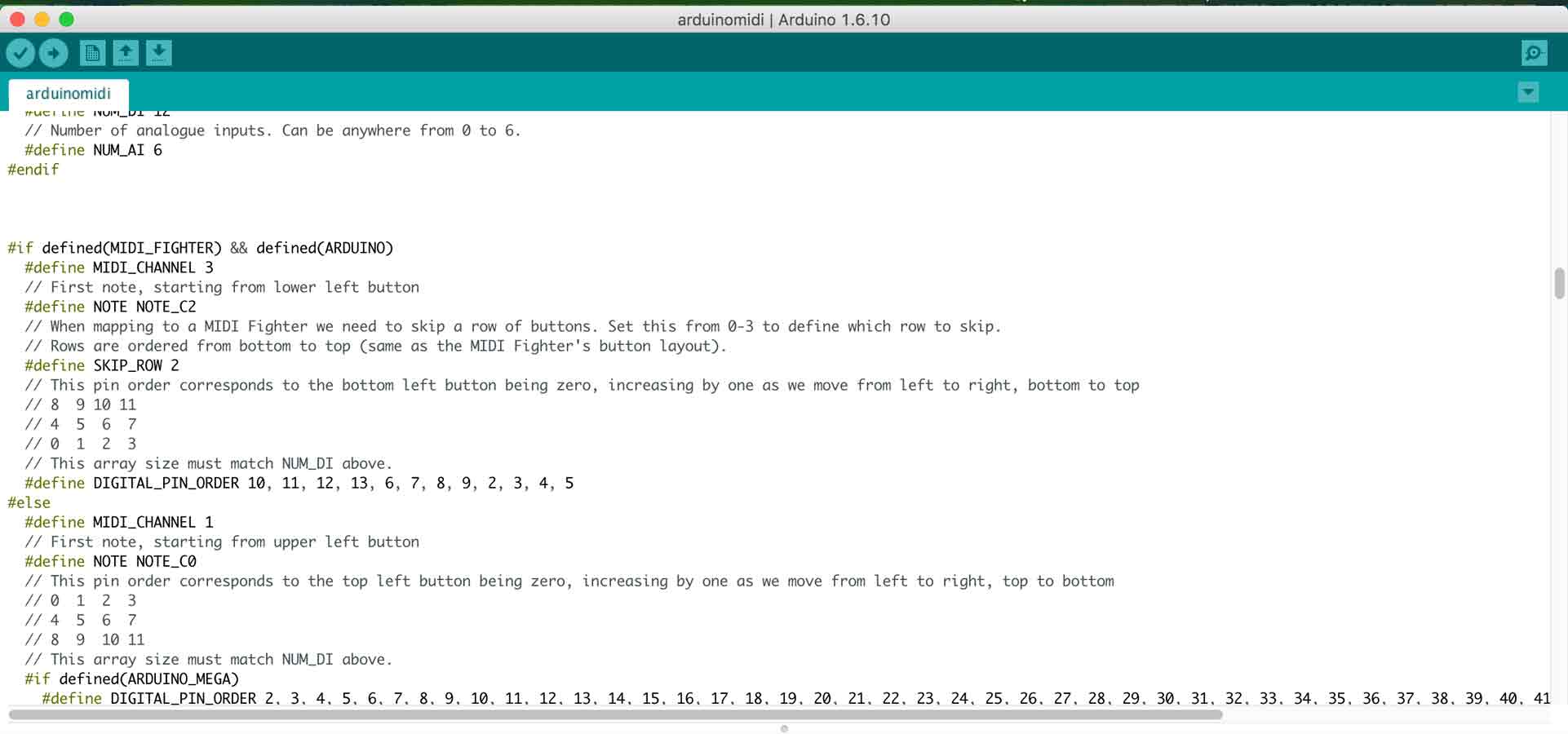
Then, we map the pins of the analogue input of the MIDI device which helps to make the music, to the MIDI notes.

In the void set up, we beigin the serial, we call the pinMode and we intialise digital with a read to the input pin.

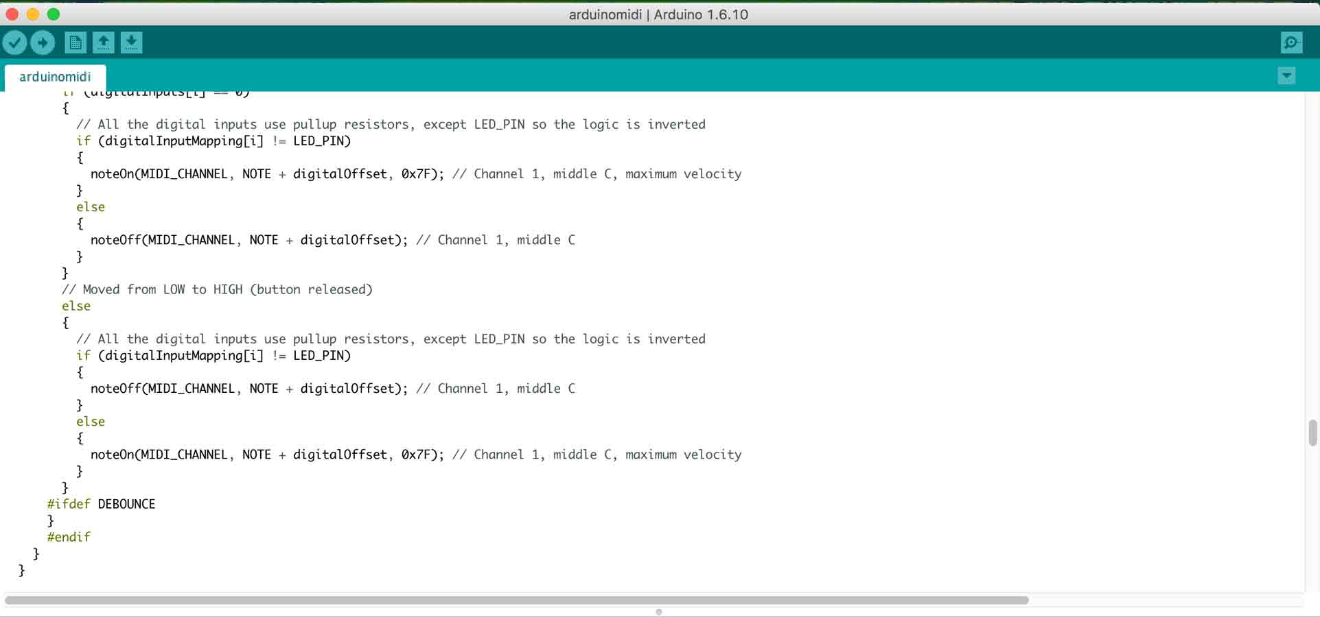
we then call the if and else functions for the MIDI note to turn on and off.
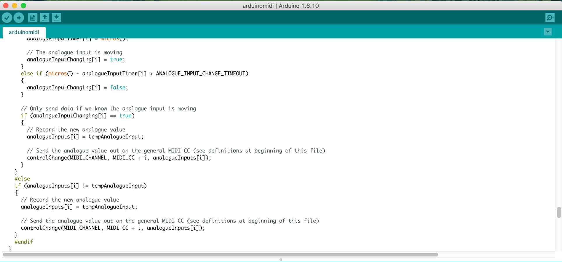
And finally define the functions of the Analogue input.
Once my board was ready and programmed , I uploaded the MIDI code from the arduino IDE on to my customised Satsha kit . In order to test it, I soldered one pin and connected it to the tactile button on the breadboard and the arduino was connected as a MIDI and was giving me the desired output and the board was successfully connected as a MIDI board.
Composite For my final project
This assignment was important for me, because I wanted this to be one of the main strategies for my final project design. Although , everyone were going for the strong mold on a 3d object, I wanted to design the oppposite and make a strong material flexible but not fragile by using composites.I learnt this amazing technique at Fabricademy Bootcamp of making wood flexible using a composite of Fabric and wood, and putting it together using Cascamite glue.
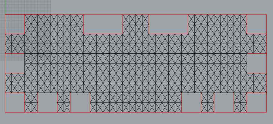
The patterns on the design give it more flexure and flexibility and also adds to the design.
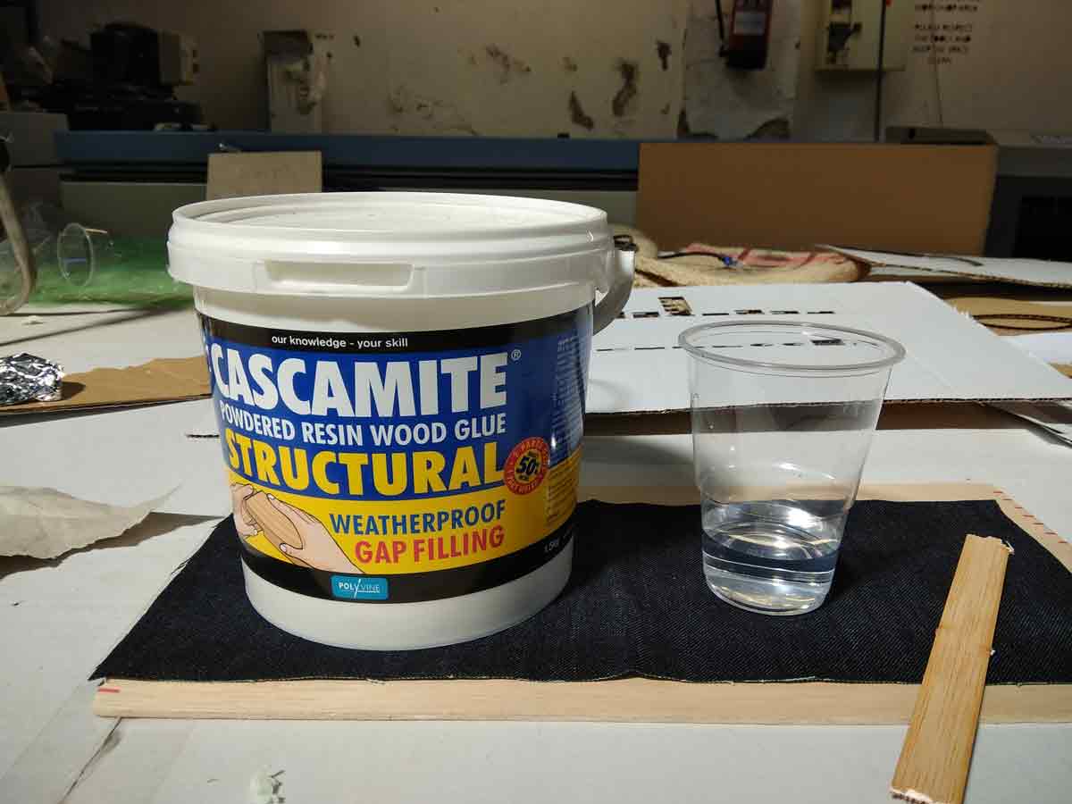
The next step was to make thw composite. For this I used 3mm wood, Jeans fabric, And Strong Wooden Glue powder called Cascamite which needs to mixed with 1:2 ratio with water.2 part of Calamite with 1 part of water.
Once I had the glue mixed, I glued the wood and the fabric and clamped it so that it sticks well. As the Vacuum Forming machine was busy, I use dthis technique but it is recommended to use the machine to press it together and make it a straing panel.

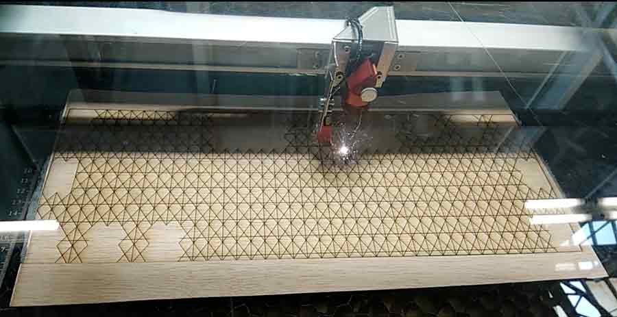
Once the glue dried, it was super strong, and I used the laser machine to engrave the pattern and the cut outs. For the seetings to use Laser machine for this composite, I got the basic settings from, FabTextiles page. The modified settings which worked for me and the one I used in the Trotec laser Machine was , Power = 70, and speed = 2 -- this was for engraving the pattern; power = 100, and speed = 1.2 -- this was for the cuttimg of rectangles where the buttons would be sticthed later.

Once the settings were set on the computer, I sent the file to the machine, and it cut perfectly.
Here is a video illustrating the basics of the process.
For my final project, This week was very important, as the MIDI device is interfacing the arduino IDE script with Ableton and from Ableton it gets interfaced to Processing.
So, what is Ableton ? Ableton is a music production software, in simple words.In the website, a very simple description says "Live is software for creating musical ideas, turning them into finished songs, and even taking them onto the stage.With two views - the classic Arrangement View, where musical ideas are laid out along a timeline, and the unique Session View, where you can improvise and quickly experiment with musical ideas - Live is a fast, fun, intuitive way to make music" . It is an incredible software used by many professionals. Here , For my project I am using the trial version of Ableton Live 9.
This website lists Free music production softwares that can be used.
This website also lists a few more Open source music production softwares that can be used.
The reason why I chose Ableton is because, it is one of the most widely used software by professionals. There is a wide range of documentation and example files and resources to learn from.
Thank to Arnau, He helped me a lot in understanding how MIDI controllers work and how to map a MIDI. First, we tried with the Korg NanoKontrol and he taught me how to map the music to the MIDI buttons/keys.
Once I tried with the commercial MIDI controller, from my input design week, I had the arduino board programmed as the MIDI controller. Therefore, My arduino was working as a MIDI controller.
I went through a lot of tutorials before , to understand the Ableton Interface. Here, I list one of the begginner tutorial I followed
Now, With my arduino board working as a MIDI controller, I first tried with the commercial arduino board to interface with ableton.
I have to mention Controllerism, this website gave me most of the resources for my project. But most importantly, It was after going through various research documents and resources online, I finally stumbled upon this one and felt like I hit a jackpot!
Here, In this video, you can see me interfacing with arduino with ableton live.
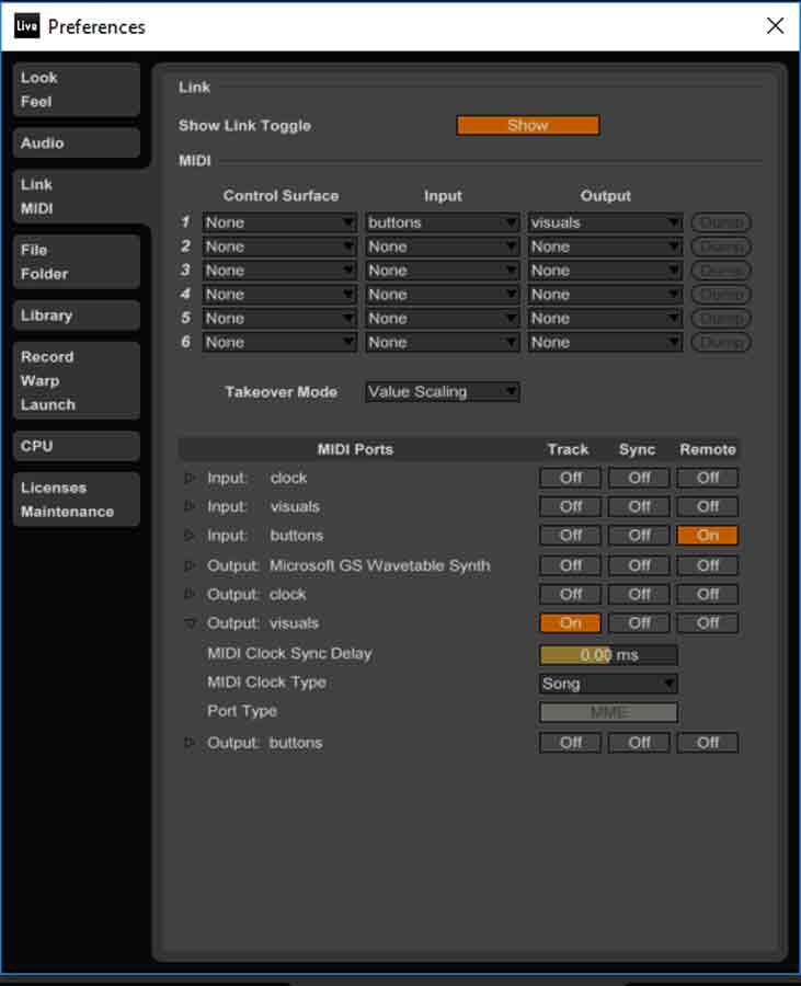
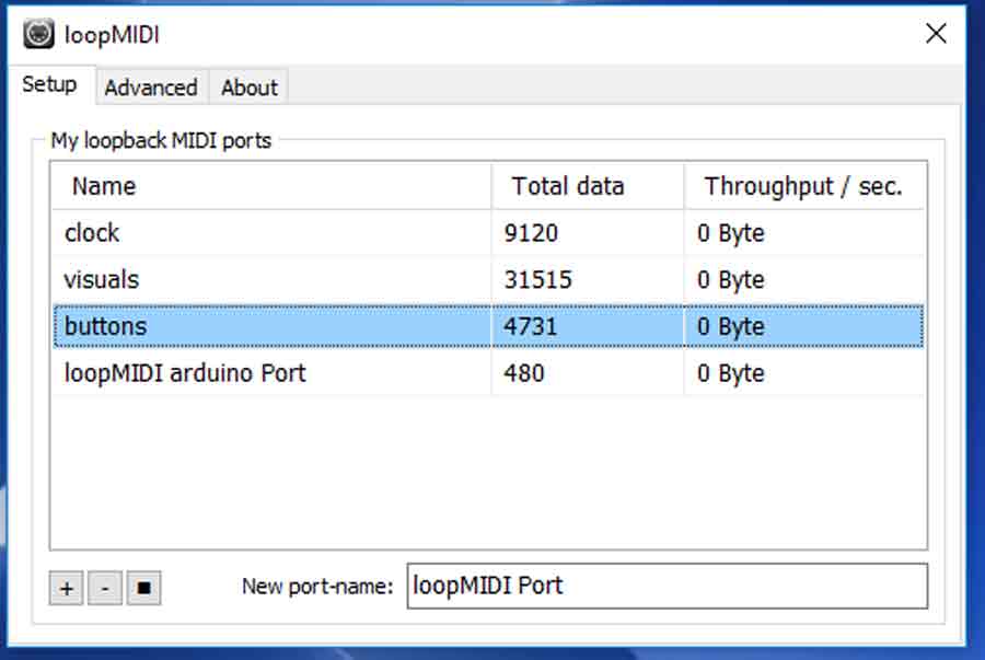
Let me give a break down of what is exactly happening in the ABLETON SOFTWARE in this project and how it is interfacing it.First you make sure, in the MIDI sync tab under preferences in ableton, the input is buttons and the output is visuals. Buttons are the analogue input coming in from the microcontroller board via virtual MIDI ports.As mine is not a commercial MIDI controller, Ableton is not able to access any libraries to connect to the board. But with the virtual MIDI ports, it shows me the options of buttons and visuals. These have been set up in the virtual MIDI port, I have writtten more about virtual MIDI ports in the project development week.
Once the MIDI is connected, In this ableton sketch we see four tracks, the drum kit, which initiates the tracks is linked with the visuals track. So the important thing to note here to interface the visuals and start the MIDI is to link the button that turns the music set on to the visual "+" , so this can kick off the drums and the visuals. Each kick core track is assigned / mapped to one analogue button connected to the microcontroller. In the MIDI mapping screen, you select a track, and click on a button and map that button onto the track.Any track that is needed can be dragged into the set and mapped onto the buttons.
This is how Ableton is interfacing with the circuit board connected to buttons.

In the input devices week, I have already spoken about how buttons are interfacing with my customised Satsha kit and ableton. But here is the video.
For my project, I also Interface with processing for generating real time visuals.Controllerism gives an in detail explanation of Ableton to Processing
Processing uses the The MIDI Bus Library to read the MIDI notes and convert it to graphics in real time.
In my final project video, we can see the basic sketch to make squares bounce to the beat of the music.
In this research project, My soft MIDI is an alteration to the usual MIDI controller. In the sense that, It works with an arduino IDE , where the PCB functions as a midi controller board.For this first step, The problems came in figuring out which libraries work with which of the arduino IDE.
To start off, I used the Instructables example in order to code my MIDI
In the arduino IDE 1.0.X , for some reason, it did not show the port in the virtual MIDI port.
In the Arduino IDE 1.8.X which is think is the lates, There were errors compiling.
In arduino IDE 1.6.X it kept saying compiling... and nothing after.

Finally, Arduino IDE 1.0.6 worked perfectly, where i could upload the code andthe port was visible on the virtual MIDI ports. More on Virtual MIDI ports below.
After I had my arduino working as a MIDI controller, I had all the circuitary made on the protoboard and connected it to the ableton software.
When I connected my programmed arduino to the music software, There were many steps to do in order to get there. Commercial softwares have libraries you can download for it to be recognised in the ableton software to connect them. Here I tried out various MIDI ports.
First I tried the Loop MIDI. With just the loop midi it did not connect and show on the ableton software in order to map my MIDI
Then , After research I realised the mac has an inbuilt Virtual port. I was using these on windows. Hence, I downloaded MIDI Yolk. This allows the wndows to have a virtual midi port. It is usually set to 8. You have to go to control panel and set the number of ports to 2 in order to not make it too heavy and for it function faster.
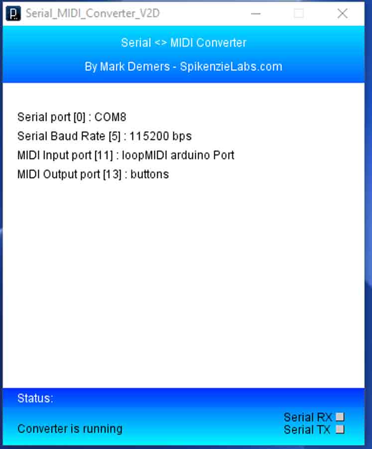
Once I had the MIDI Yold, it was time to download Serial MIDI. This connects the virtual port on the computer, here it is MIDI yolk to the midi port in the music software.
But this did not recognise the arduino on ableton software either. Hence, I used LoopMidi which was recognising my arduino port. From this loop midi posrt i connected to SerialMIDI which was being recognised in the ableton software.Here are the images showing the right configurations to connect the arduino MIDI to the ableton software.
Once i had this configured, I mapped the arduino on Ableton Live. In order to use the arduino and virtual midi ports in ableton live, These are the settings in preferences that I made.
Once the Arduino port is recognised on the MIDI preferences in ableton, I mapped the MIDI on ableton
After this process was working , I connected my Satsha kit, from my output devices assignemnt week, and the buttons to satsha kit from Input devices assignment week, And had my soft MIDI controller working!
Conductive buttons ~ 2 euros for a set of 8 buttons
insulated copper wire ~ 25 euros for a 15 meter roll
3mm or 4 mm wood ~ 10 euros for 1000 mm by 500 mm peice
Fabric to make composite ~ 10 euros
a small portiion of wood glue ~ 5 euros

This work is licensed under a Creative Commons Attribution-NonCommercial 4.0 International License.
I would like to thank all my tutors , Santi Fuentemilla, Xavi Dominguez , Arnau and Citlali for their immense support at all stages of my Fab academy process. I also want to thank my batch of Fab Academy 2017, Fab Lab Barcelona group for always looking out and being there!
To view and download files click HERE.
To download files click HERE
THANK YOU