Embedded Programming
Week 8
Embedded Programming
Tasks
read a microcontroller data sheet
Program your board to do something, with as many different programming languages
and programming environments as possible
Extra credit: experiment with other architectures
Reading microcontroller datasheet
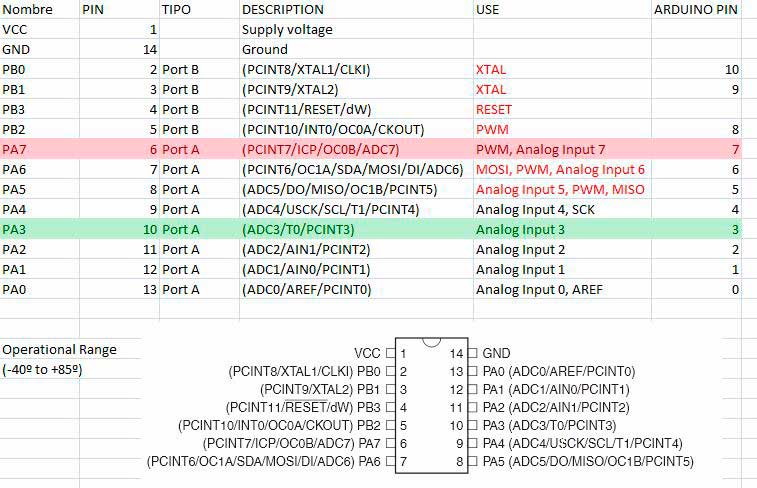
After reading the datasheet of the Attiny44 microcontroller, i made a spreadsheet to show the components of the micro. In red is the pin of the led and in green is the pin of the button:
Microprocessor Sheet
Programming
I'm going to program the board using Arduino IDE Software, so the first thing I have to download is the Arduino programming environment, with installation instructions are available above.
NEEDS:
Software:
Arduino
Attiny Library
FTDI Drivers
Datasheet:
Attiny
Components:
FABISP
LED + Button board
FDTI Cable
6 Pin Cable
Mini USB Cable
Steps:
- Install Arduino IDE and FTDI Drivers
- Install Attiny Library - Arduino hasn't Attiny library by default, so it's needed to install it. Locate your Arduino sketchbook folder (you can find its location in the preferences dialog in the Arduino software) in windows usually: "C:\Users\YOU_USER\Documents\Arduino\" . Create a new sub-folder called "hardware" in the sketchbook folder. Copy the attiny folder from inside the .zip to the hardware folder. With these changes, the next time you restart, you should see in the Arduino IDE Software ATtiny's boards
- Connect the Hello board with the ISP programmer by using an ISP connector cable
- Connect the ISP programmer to the computer by using a USB cable
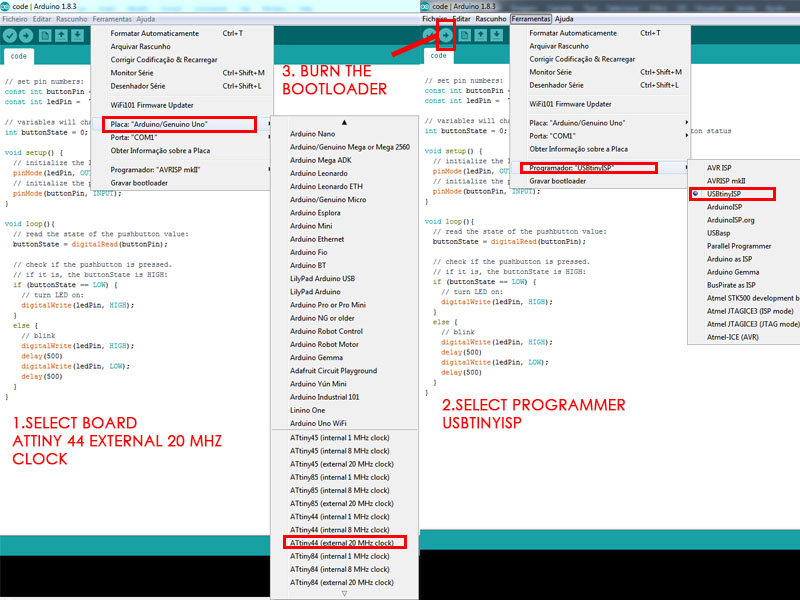
- Inside Arduino, follow these steps:
Arduino steps
Arduino Code explained
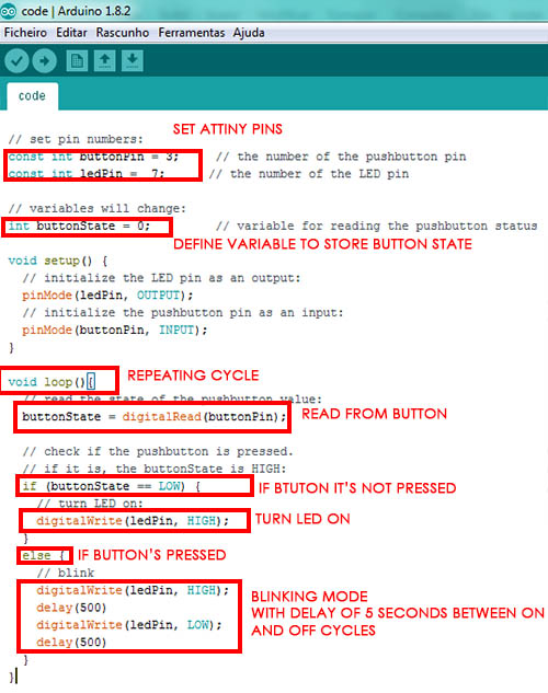
Programming the board was very interesting to understand how attiny works inside Arduino! Example files are very usefull for those that are trying for the first time! About programming with other architectures i followed my colleague assignments. I tried to program with different parameters, by switching the led effects, changing the delay of the blinking mode etc..
Testing the program
The code
// set pin numbers:
const int buttonPin = 3; // the number of the pushbutton pin
const int ledPin = 7; // the number of the LED pin
// variables will change:
int buttonState = 0; // variable for reading the pushbutton status
void setup() {
// initialize the LED pin as an output:
pinMode(ledPin, OUTPUT);
// initialize the pushbutton pin as an input:
pinMode(buttonPin, INPUT);
}
void loop(){
// read the state of the pushbutton value:
buttonState = digitalRead(buttonPin);
// check if the pushbutton is pressed.
// if it is, the buttonState is HIGH:
if (buttonState == LOW) {
// turn LED on:
digitalWrite(ledPin, HIGH);
}
else {
// blink
digitalWrite(ledPin, HIGH);
delay(500)
digitalWrite(ledPin, LOW);
delay(500)
}
}
Here is the other code i programmed in my final project
UPDATE 08-07-2016
Programming in C
Next thing to do is programming in C. i had to prepare the .c and .make files. I reused Neil's code and made some changes. If the button is not pressed, led keeps off, if it's pressed, led blinks:
#include <avr/io.h>
#include <util/delay.h>
//Define constant for the 1 second delay
#define blink_delay 1000
int main(void)
{
//SETUP
//Button is on PA3
//LED is on PB7
DDRA |= _BV(PA7); // Enable output on LED pin 3
PORTA = _BV(PA3); // Activate button
//LOOP
while (1)
{
if(PINB & _BV(PB2)) //button is not pushed
{
PORTA = 0; //KEEP LED OFF
}
else // button is pushed
{
PORTA |= _BV(PA7); // turn LED on
_delay_ms(blink_delay);
PORTA = 0; // turn LED off
_delay_ms(blink_delay);
}
}
}
Next thing to do is to compile and program the boards. In Ubuntu, with AVRDUDE installed, go to terminal and change to your project directory. REMEMBER to change your makefile first line like this:
PROJECT=YOURFILENAME.echo
Connect computer and FabISP board via USB
Connect Fabisp + Led.button boards together via ISP Ribbon Cable correctly
Plug FTDI cable into board
Now that you're in terminal, type:
$ make -f JM_blink.c.make
avr-gcc -mmcu=attiny44 -Wall -Os -DF_CPU=20000000 -I./ -o JM_blink.out JM_blink.c
avr-objcopy -O ihex JM_blink.out JM_blink.c.hex;\
   avr-size --mcu=attiny44 --format=avr JM_blink.out
AVR Memory Usage
----------------
Device: attiny44
Program:     848 bytes (20.7% Full)
(.text + .data + .bootloader)

Data:         33 bytes (12.9% Full)
(.data + .bss + .noinit)
Next: make -f JM_blink.c.make program-usbtiny
$ make -f JM_blink.c.make program-usbtiny
avr-objcopy -O ihex JM_blink.out JM_blink.c.hex;\
avr-size --mcu=attiny44 --format=avr JM_blink.out
AVR Memory Usage
----------------
Device: attiny44
Program: 848 bytes (20.7% Full)
(.text + .data + .bootloader)
Data: 33 bytes (12.9% Full)
(.data + .bss + .noinit)
avrdude -p t44 -P usb -c usbtiny -U flash:w:JM_blink.c.hex
avrdude: AVR device initialized and ready to accept instructions
Reading | ################################################## | 100% 0.00s
avrdude: Device signature = 0x1e9207
avrdude: NOTE: FLASH memory has been specified, an erase cycle will be performed
To disable this feature, specify the -D option.
avrdude: erasing chip
avrdude: reading input file "JM_blink.c.hex";
avrdude: input file JM_blink.c.hex auto detected as Intel Hex
avrdude: writing flash (848 bytes):
Writing | ################################################## | 100% 0.82s
avrdude: 848 bytes of flash written
avrdude: verifying flash memory against JM_blink.c.hex:
avrdude: load data flash data from input file JM_blink.c.hex:
avrdude: input file JM_blink.c.hex auto detected as Intel Hex
avrdude: input file JM_blink.c.hex contains 848 bytes
avrdude: reading on-chip flash data:
Reading | ################################################## | 100% 0.49s
avrdude: verifying ...
avrdude: 848 bytes of flash verified
avrdude: safemode: Fuses OK
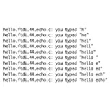
avrdude done. Thank you.Now let's test the programmed board:
FILES
C Program
Making the Cables
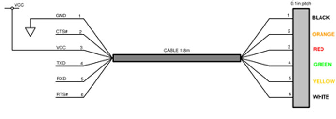
After reading some electronic tutorials and watching some picures, i started by building the FDTI cable and the 6 PIN cable so i can connect the 2 boards.
FDTI Cable wiring scheme
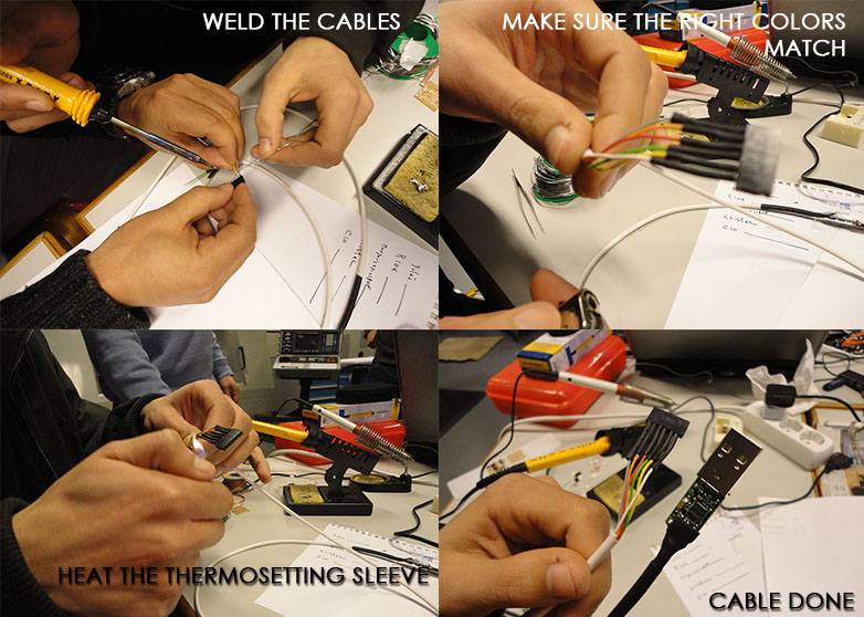
Assembling the FDTI Cable
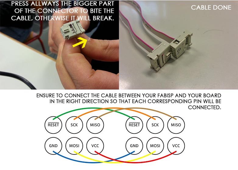
Assembling the 6 Pin cable
TIPS:
-Verify the connections with a multimeter and make sure that mostly VCC and GRND and the other connections are well done.
-Verify ATtiny 44 MCU Pin diagram and be sure that the pin numbers correspond to the pins used for the LED and the button in your board.
FILES
Arduino Program
References - ATtiny Embedded Programming with the Arduino ,