Project Development
what tasks have been completed, and what tasks remain?
Completed: Structure plans, materials and building diy, Greenshouse cover material, Structure tested, electronic circuit done and tested, humidity and temperature monitored, site updated, final video and slide, assembly tests , documentation, ventilation system, misdt maker tests, interior lighting,
Remaining: Mist maker programming, build a bigger water deposit, embed a MCU, cool packaging, fully waterproof system
what has worked? final structure assembly, humidity and temperature sensor, arduino circuit, mist maker, ventilation system
what hasn't? I Havent't tried to grow mushrooms yet, i must wait for the winter, it's too hot now, Test the irrigation system,
what questions need to be resolved? Is it ok to assemble in acrylic? Is there another way to cover the structure instead of individual pvc foils? is it needed a fan to spread the mist (yes, i've tested)?
what will happen when? After my final presentation i'll talk with the Cogus CEO to analyse product development process and the improvements he wants me to make. By the end of the summer the tests with real cultures will start and improvements in the structure will be made
what have you learned?A lot
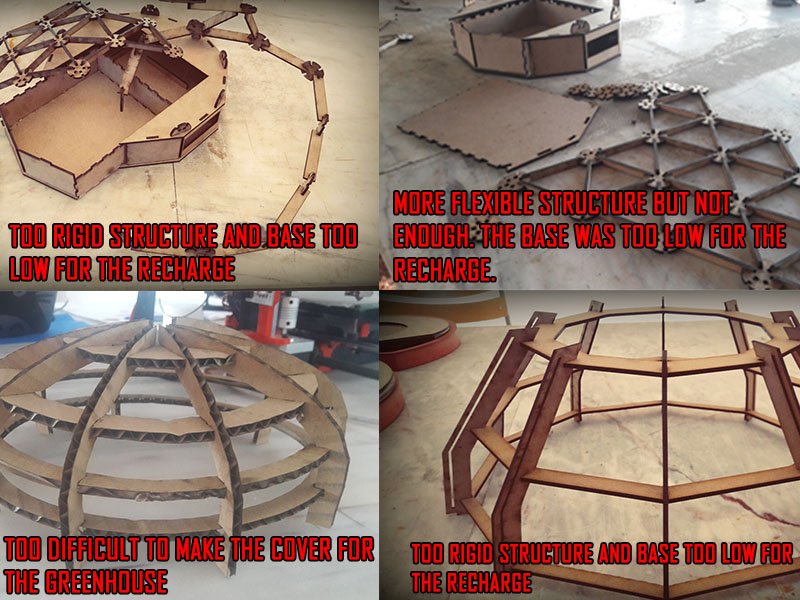
The prototype structure
I've started to stutying the structure of my greenhouse. After doing some research about geodesic domes calculators and some interesting fabacademy projects, i've tested a geodesic dome, and basically it didn't work, mainly for 2 reasons:- The pressfits modules didn't fit together because of the plywood thickness
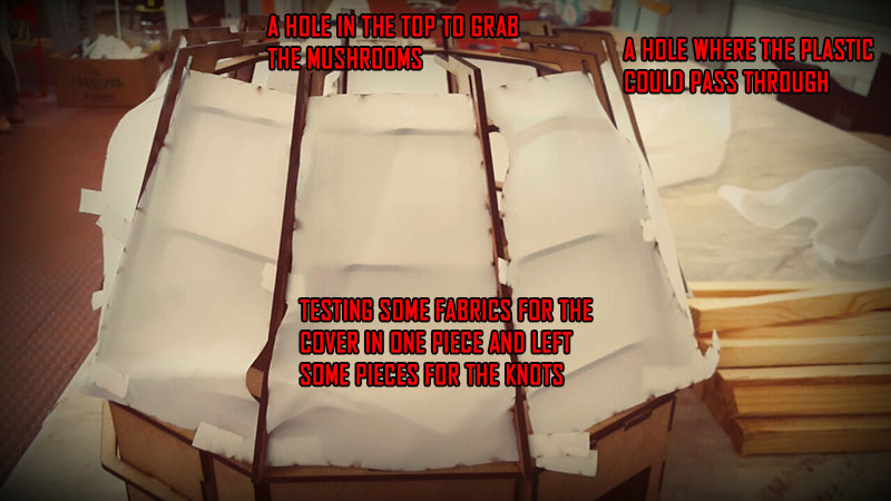
- The final cover for the greenhouse was difficult to make
Some structure fails
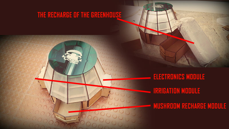
I want my prototype to work like a diy kit, where the greenhouse owner must assemble all the structure and prepare all the systems on an easy way. That's why i decided on this shape:
As you can see it's more simple to assemble and by cutting some pvc film parts you can easilly put into the structure parts all together. I had to enlarge the base weight for the mushroom recharge could fit in its box and create isolated modules for the electronics and the irrigation system.
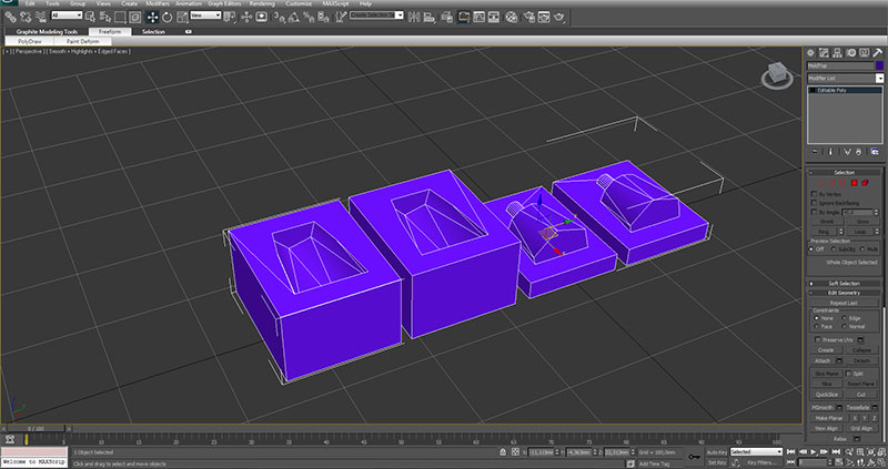
Prototype Modules
For the water container i made a simple mold to cast, that enough water could fit without boiling out and damage the electronics. Prototype Modules
I've updated the structure, because i started to embed the electronic system into my prototype and realised some components won't work. I made a few adjustments:
Changes to the structure
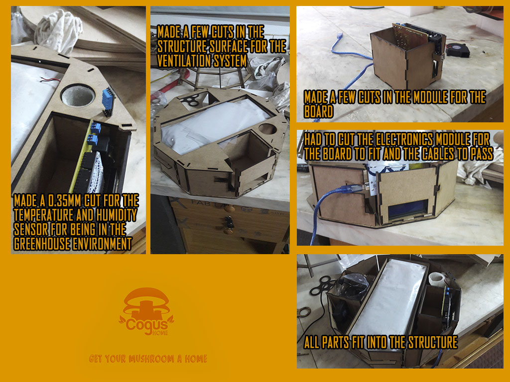
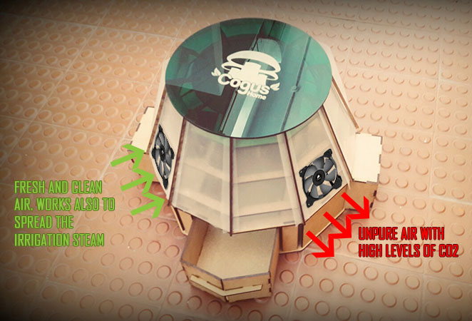
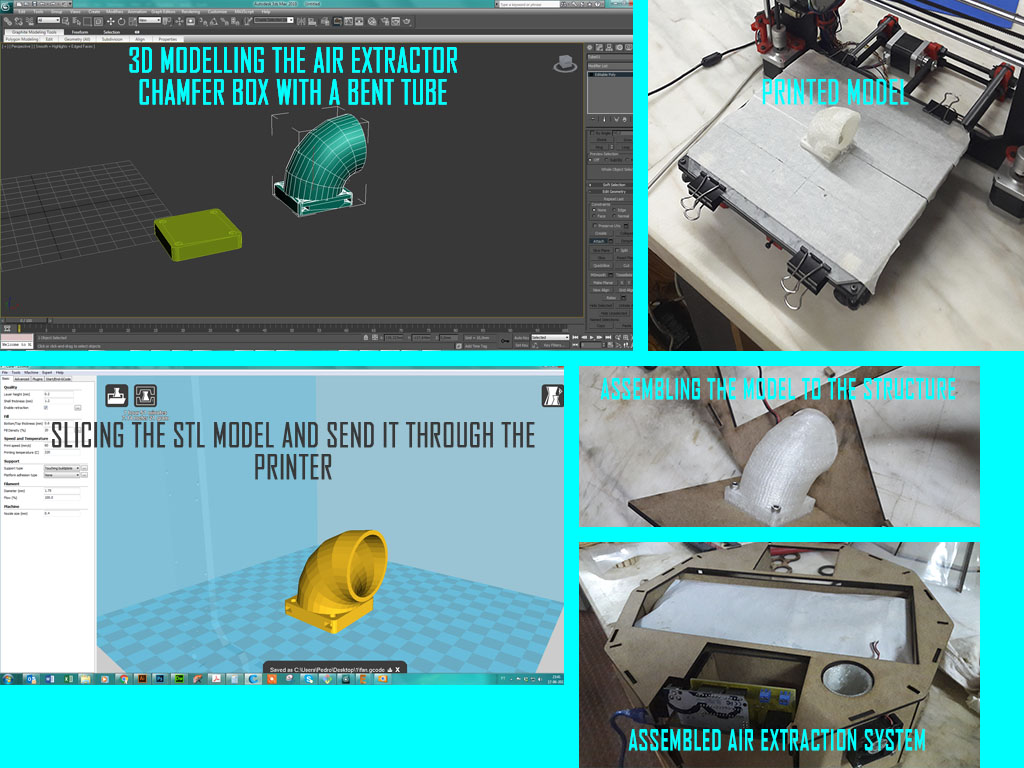
I did a few research and realised that there was needed a ventilation system to recycle the air inside the greenhouse, and reduce the CO2 levels. So i decided to implement 2 fans, one air in and other air out. For the extraction fan i 3d modelled a pipe that could extract the air through the fan and made a hole in the irrigation module to receive the blower fan. Perhaps later i will integrate a co2 sensor to monitor the CO2 levels inside the greenhouse.
Ventilation module workflow
Prototype Modules
Video testing the fog blowing system
In the final product i'm going to use 3mm acrylic for the prototype, because plywood is no waterproof and the greenhouse might damage with the irrigation system.
FILES
3d Model for the water container
3d Model for the fan
final files of the structure
References - Fabacademy Student
Fabacademy Student
Fabacademy Student
Geodesic Dome Online calculator
The Electronics
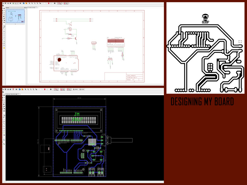
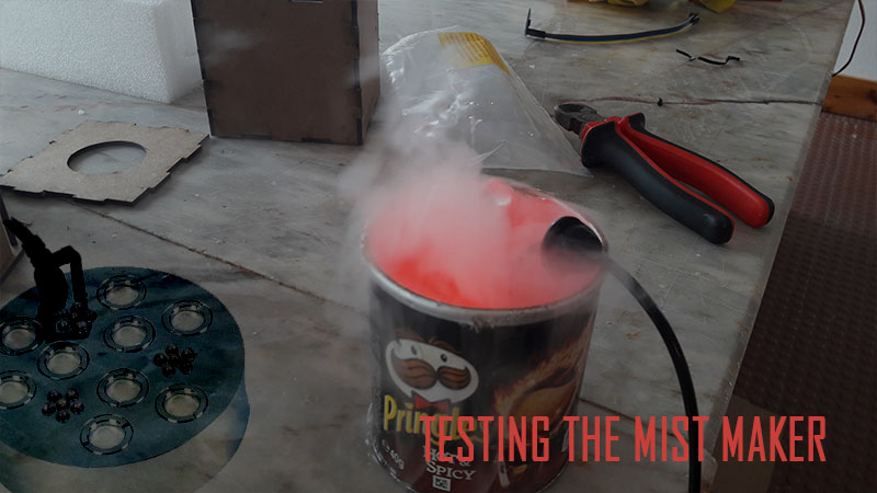
I've started this task by searching some interesting projects with temperature and humidity sensors, and after finding some stuff online i began to build my own circuit. These were the components i needed: -Relay 5v 1A -1 Diode DO41-10 -1 Resistor 4,7k -1 Transistor TO92 -1 Resistor 220 Ohm -Pin header female - 50 pin headers -Pin header Male - 8 pin headers -Conectores de pcb- 2 units of 2 pins each -Humidity and Temperature sensor DHT11 -Ultrasonic Nebulous (Mista maker) it was very interesting to know arduino better and i felt i've developed new electronic skills. I've worked the circuit and added a servo motor to test the output results. Now i'm working with the mist maker, that will serve the irrigation system of my prototype. I'll need an external 24v power supply to feed the mist maker. After a few research i figured that the water steam is the best way to irrigate the mushrooms, because it will not harm them and it will keep good thermic conditions inside the greenhouse. I've started to make a board working with the attiny45 microcontroller, somekind of shield that can fit into my electronics module inside the structure. For the mist maker i'll need an external power supply of 24V. Here's the circuit:Board design in Eagle
Mist Maker
Board soldering and assembly process
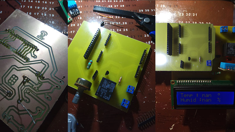
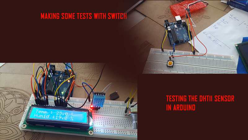
Testing the electronic components in arduino
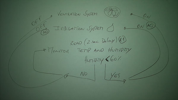
Programming the board wasn't so easy. I've tested a few scripts to know what they did and i had to adjust them to my needs. Here's a scheme of my program:
Board design in Eagle
Fabkit
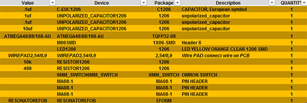
I was advised to change arduino connecting with a board made by me, and after searching i decided to make the fabkit, an Arduino-compatible board designed by David Mells that could help me make a fully customized electronic kit for Cogus Home. I started to editing the needed files and collecting the components, designing the board in eagle and programming the board using arduino.Needed components
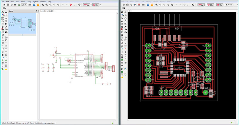
Board design in Eagle
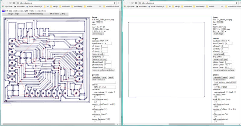
Preparing milling files in fabmodules
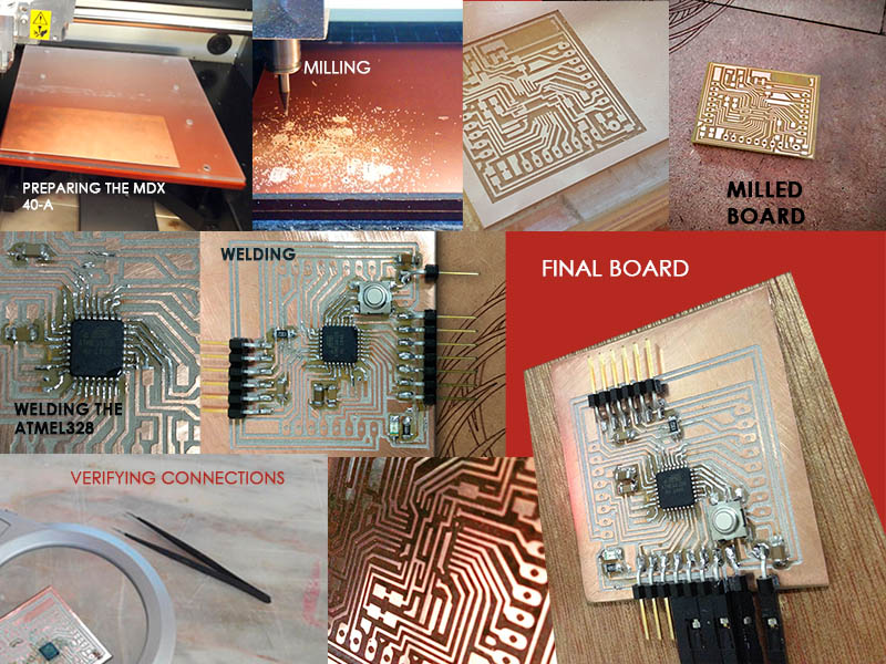
Board production process
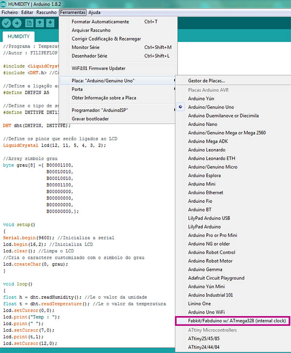
In order to program my board i had to add some code into Arduino default boards.txt file (C:\Program Files (x86)\Arduino\hardware\arduino\avr).
##############################################################
fabduino.name=Fabkit/Fabduino w/ ATmega328 (internal clock)
fabduino.upload.protocol=stk500v1
fabduino.upload.maximum_size=14336
fabduino.upload.speed=19200
fabduino.bootloader.low_fuses=0xe2
fabduino.bootloader.high_fuses=0xdd
fabduino.bootloader.extended_fuses=0x00
fabduino.bootloader.path=arduino:atmega
fabduino.bootloader.file=atmega/ATmegaBOOT_168_atmega328_pro_8MHz.hex
fabduino.bootloader.unlock_bits=0x3F
fabduino.bootloader.lock_bits=0x0F
fabduino.build.mcu=atmega328p
fabduino.build.f_cpu=8000000L
fabduino.build.core=arduino:arduino
fabduino.build.variant=arduino:standard
fabduino.upload.tool=arduino:avrdude
fabduino.bootloader.tool=arduino:avrdude
Selecting my board in arduino
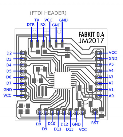
Checking what ATMega328 pins to program
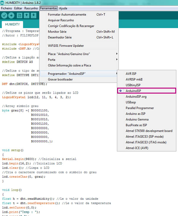
I Choosen your ISP with Tools > Programmer (Arduino as ISP if you use an Arduino):
Selecting my programmer
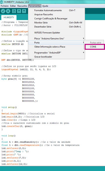
Next select your com port:
Selecting my programmer
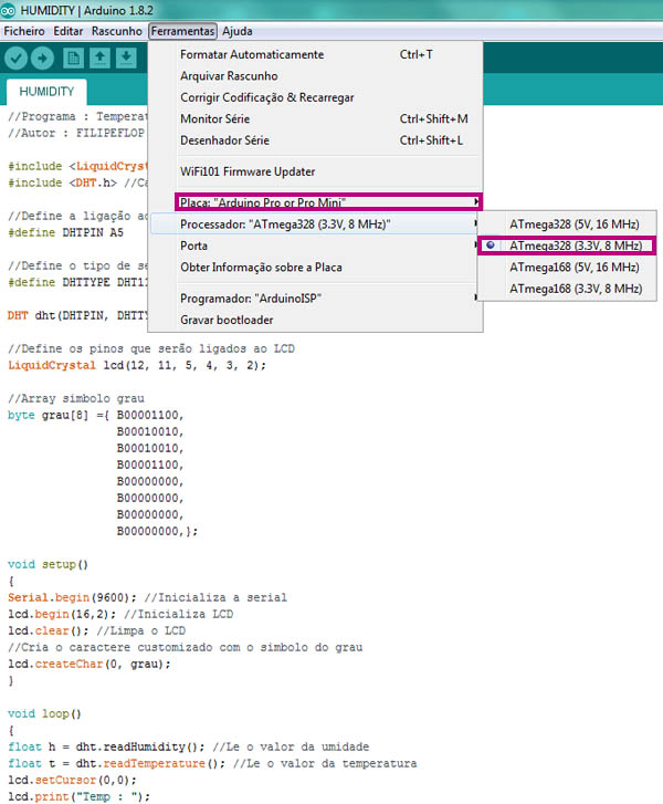
After compiling the code, i realized the board wasn't connecting properly and an error apeared. This happens because my version of Arduino (1.8.2)is greater than the fabkit advices (code updated for Arduino IDE v.1.6 which has some different settings).
Seams Hyejin Park had the same problem, and according to him i must select another board:
Update my programmer
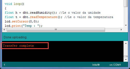
Tested upload bootloader, and that's it!
Uploading bootloaderr
Web Interface
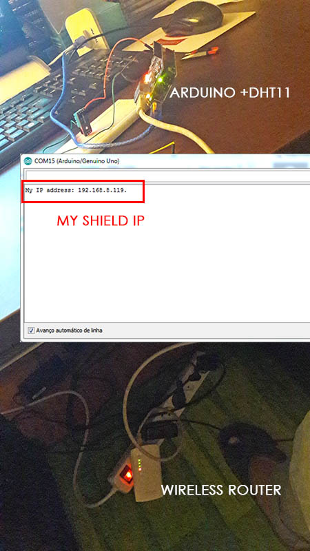
UPDATE 06-07-2017I started to search about what kind of connections with dht11 were possible to show the data in a web browser. There are a few ways to do it, locally, by sending through serial monitor to webserver, or using an ehternet shield for my board. I first tested it in Arduino, with an Arduino ethernet shield w5100 and opened the sample Arduino Ethernet, compiled it through com15 to arduino and voila:
testing connections and grabbing ip
Arduino Code for Ethernet shield
#include <SPI.h>
#include <Ethernet.h>
#include <ThingerEthernet.h>
#define USERNAME "your_username"
#define DEVICE_ID "your_device_id"
#define DEVICE_CREDENTIAL "your_device_credential"
ThingerEthernet thing(USERNAME, DEVICE_ID, DEVICE_CREDENTIAL);
void setup() {
pinMode(2, OUTPUT);
// pin control example (i.e. turning on/off a light, a relay, etc)
thing["led"] << digitalPin(2);
// resource output example (i.e. reading a sensor value, a variable, etc)
thing["millis"] >> outputValue(millis());
// more details at http://docs.thinger.io/arduino/
}
void loop() {
thing.handle();
}
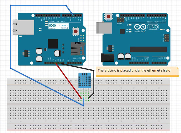
Now that i knew my IP and it was connected, was time to test it with my DHT11 humidity and temperature sensor with this ethernet shield.
I found some usefulle tutorials that you can find in References below, and they gave me the essential kick to start my own code.
Arduino connection
After setting connections and starting to write my own code i tested my serial monitor and see if i could get some results.
Testing DHT11 Data
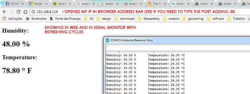
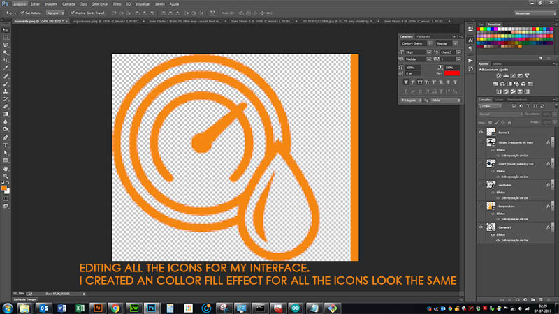
Now that i have my values shown in web, i need to create a proper interface to my CogusHome. I created some png's for my interface icons. I had to store them online because there's no way to link them locally, only by URL
Creating icons
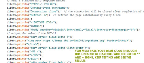
Next step was to edit my code and try to get a good HTML through Arduino client.println code. I used div's for aligning properly my text, otherwise text and pictures would stay line after line
HTML interface programming
And there's my final result: HTML final interface
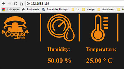
I tried to add my actuators through this interface and searched a few more ways to do it and found a very usefull link that stores a html file in a SD Card and sends the arduino's output to it. I'm keen on making this happen, because it supports html files, css and it's easier to config. But for now i just made the html interface. SEE HERE
FILES
Arduino files, png's source
References -
Webserver-HTML button
CSS/HTML
Icon finder
Ethernet shield
Also a good way to connect
Final Test
Here's a video of my final test, wich i inverted the humidity values to test the irrigation and ventilation system (greater than 60%) and took out the DHT11 sensor, otherwise wouldn't be possible for the values to lower. As you can see, when it came to 60% or less, the systems disables the irrigation and ventilation system. Hope you like!Video testing the prototype
FILES
Eagle, png and rml files of the boards
Program file
References -
Arduino Tutorial
Arduino Tutorial
Geodesic Dome Online calculator
Fabacademy Student Input devices assignment with DHT11
Mist Maker working
SatshaKit Page
Sabina Barcucci Fabkit Page
Massimo Bianchini Fabkit Page
FabKit
ATMega 328 datasheet
Humans that Make Harduino Board