Electronics Production
Week 4
Electronics Production
Tasks
Individual assignment:
make an in-circuit programmer by milling the PCB, then optionally trying other processes
Preparing the Roland Modela mdx-40a
We started this week looking at the forth axis installed on our modela and removing it. We had to level the plate for better milling results. We cutted 305mm square of a 8mm acrylic in the lasercut and milled 0.5mm depth with a 6mm end mill at 0.6mm of stepdown, 7500RPM, 2.6mm of stepover with a 40mm/sec feedrate. Next time we'll reduce the stepover for smoother results. Next time i'll also change the clearance for the screws. I made a 5mm clearance in the material and only left 3mm to support tha screws, and it stayed too fragile. I think a 3mm area are enough for hiding the screws from the milling surface.
Modela MDX 40A Fourth Axis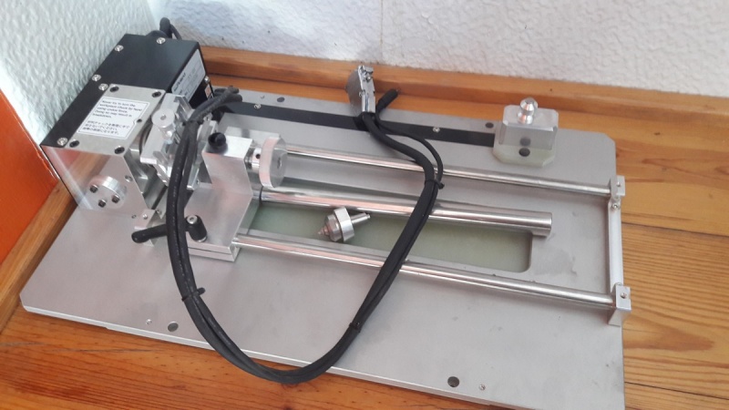
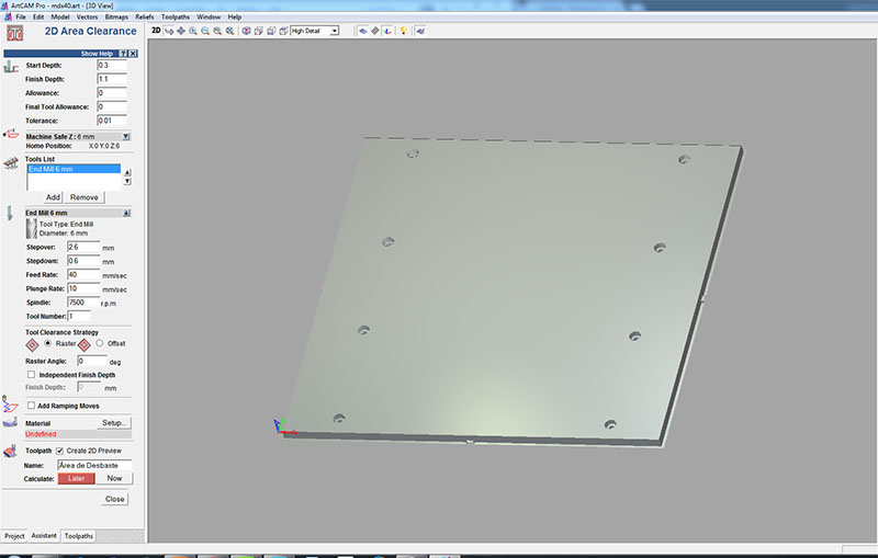
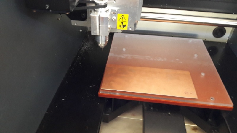
Working with Artcam in the modela
Final Result
FILES
Artcam file
Plate Vector File
References - Roland Modela MDX-40A manual,
PCB Fabrication
I choose Brian "FabTinyISP Minimal", a Bas Zaerc's ISP with few modifications tutorial. I choose this because i liked its shape, and in our group we decided to make 2 diferent FabISP's. After reading a while i come to some conclusions:
Less components needed
The LEDS facilitate usage
Easy way of removing the bridge/jumpers
Practical use in USB slot
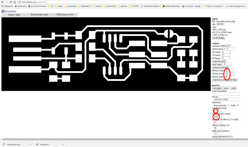
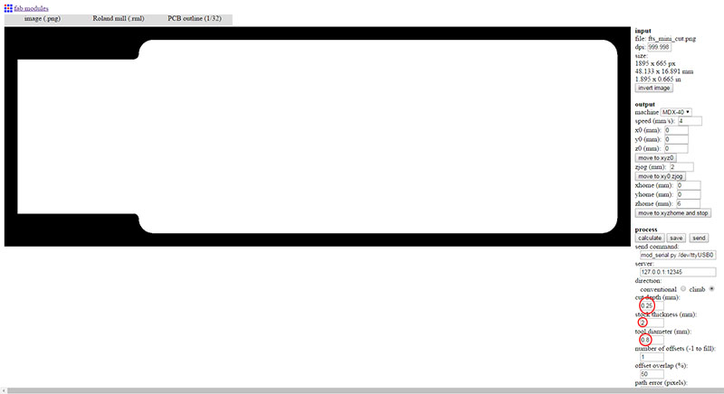
I started by downloading the traces and the outline cutout. I used Fabmodules HTML5 to get the clearance an cutting paths. Here are the steps i followed:
input format --> image (.png) --> select the png file
output format --> Rolland mill (.rml)
Process --> PCB Traces (1/64)
Then i changed a few parameters, as seen on the picture below, for better results. I changed the zhome (mm): to 6mm for the jog in the end of the milling go up for a safe Z of 6mm, otherwise the PCB could get damaged.
Parameters for Fabmodules
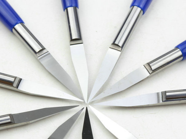
0.25mm V Cut PCB Carbide End Mill (very nice results)
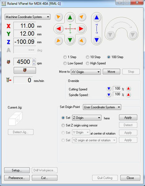
I grabed a PCB board and attach it to the plate using double sided Adhesive tape. Then i had to set the origins in the modela Vpanel. The X and Y are easier to define, but the Z axis is a bit more complicated. I used a paper and changed the speed of the motor to 1 step at a time until i reached the paper and i couldn't move it more. When it stucks, the Z oringin is set!
Sticking to the board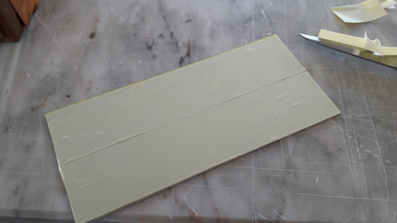
Attaching to the plate
Seting Z origin with paper
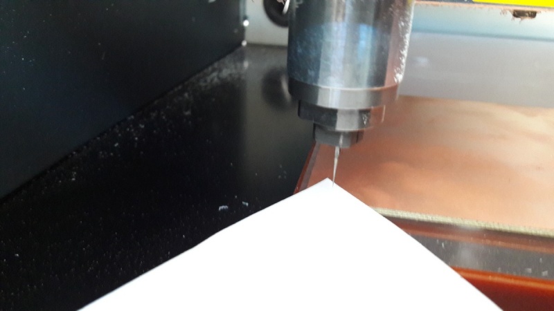
Using Roland Vpanel
Next step was to cut the board. I used the cuting png and in fabmodules:
input format --> image (.png) --> select the cutting png file
output format --> Rolland mill (.rml)
Process --> PCB Outline (1/32)
I changed a few parameters again, because my board was thicker (2mm) and reduced the stepdown to 0.25mm. i used a 0.8mm endmill. It did a nice cut. I could see that it was cut because of the remains of the adhesive tape sticked to the mill.
Here is the final result of my PCB after using a knife to remove the copper remains in the board.
Final Result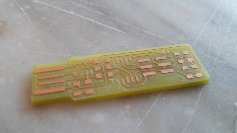
Next i had to gather all the components to start and do the weldings. It was a bit more complicated because the components were arriving to the Lab and we had to pack properly all of them.
A bit of a mess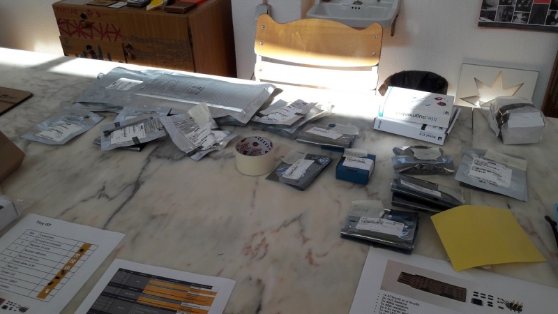
Final Packing Result
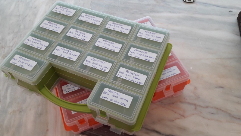
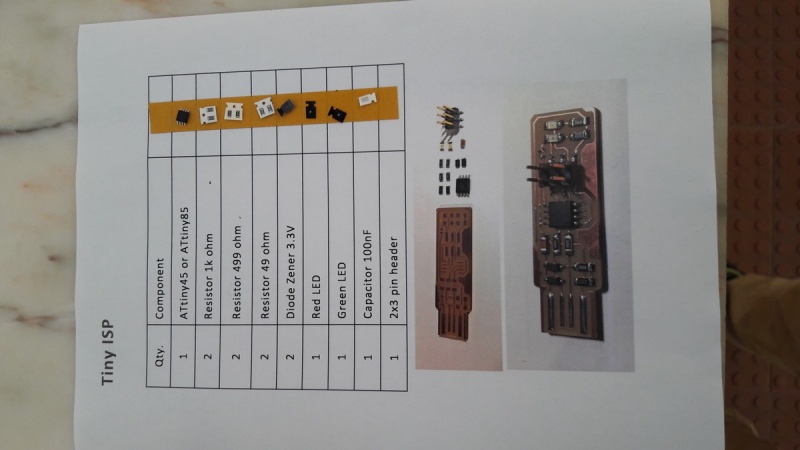
My components ready
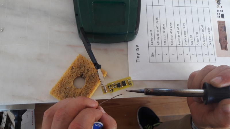
I started the welding process with calm and with precision the first components started to appear in the board. I took a break after 15 minutes of welding to relax hands and muscles, i suggest you do it too.
First components welded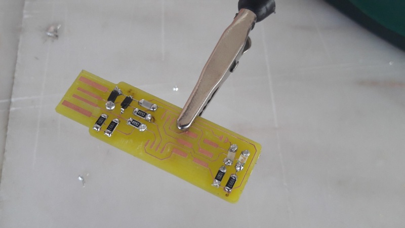
I used a bit of welding paste, because some of the copper tracks were really thin. I was also helped by using the schematic and board images that i printed
Schematic pictures helping the welding process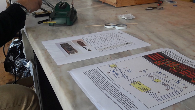
Welding with the help of a friends hand (tweezers)
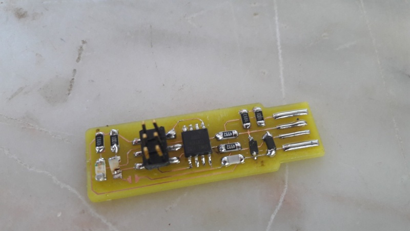
Final Result
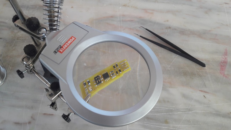
Analysing the board through a magnifying glass
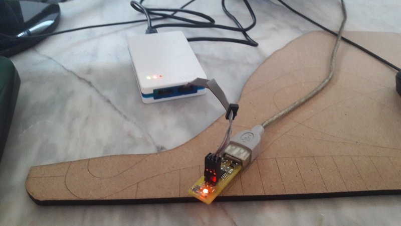
Next step is to program the board. I've already did some tests and the LED turned on! Steps to program the board:
Edit Makefile and change programmer name on PROGRAMMER ?= atmelice_isp
Flash the program to the board - Run make flash
avrdude -p attiny45 -c usbtiny -P usb -e \
-U flash:w:fts_firmware.hex
avrdude: AVR device initialized and ready to accept instructions
Reading | ################################################## | 100% 0.01s
avrdude: Device signature = 0x1e9206 (probably t45)
avrdude: erasing chip
avrdude: reading input file "fts_firmware.hex"
avrdude: input file fts_firmware.hex auto detected as Intel Hex
avrdude: writing flash (2448 bytes):
Writing | ################################################## | 100% 5.50s
avrdude: 2448 bytes of flash written
avrdude: verifying flash memory against fts_firmware.hex:
avrdude: load data flash data from input file fts_firmware.hex:
avrdude: input file fts_firmware.hex auto detected as Intel Hex
avrdude: input file fts_firmware.hex contains 2448 bytes
avrdude: reading on-chip flash data:
Reading | ################################################## | 100% 9.56s
avrdude: verifying ...
avrdude: 2448 bytes of flash verified
avrdude: safemode: Fuses OK (E:FF, H:DF, L:62)
avrdude done. Thank you.
Setting up the fuses - Run make fuses
avrdude -p attiny45 -c usbtiny -P usb \
-U lfuse:w:0xE1:m -U hfuse:w:0xDD:m \
-U efuse:w:0xFF:m
avrdude: AVR device initialized and ready to accept instructions
Reading | ################################################## | 100% 0.01s
avrdude: Device signature = 0x1e9206 (probably t45)
avrdude: reading input file "0xE1"
avrdude: writing lfuse (1 bytes):
Writing | ################################################## | 100% 0.01s
avrdude: 1 bytes of lfuse written
avrdude: verifying lfuse memory against 0xE1:
avrdude: load data lfuse data from input file 0xE1:
avrdude: input file 0xE1 contains 1 bytes
avrdude: reading on-chip lfuse data:
Reading | ################################################## | 100% 0.00s
avrdude: verifying ...
avrdude: 1 bytes of lfuse verified
avrdude: reading input file "0xDD"
avrdude: writing hfuse (1 bytes):
Writing | ################################################## | 100% 0.01s
avrdude: 1 bytes of hfuse written
avrdude: verifying hfuse memory against 0xDD:
avrdude: load data hfuse data from input file 0xDD:
avrdude: input file 0xDD contains 1 bytes
avrdude: reading on-chip hfuse data:
Reading | ################################################## | 100% 0.00s
avrdude: verifying ...
avrdude: 1 bytes of hfuse verified
avrdude: reading input file "0xFF"
avrdude: writing efuse (1 bytes):
Writing | ################################################## | 100% 0.00s
avrdude: 1 bytes of efuse written
avrdude: verifying efuse memory against 0xFF:
avrdude: load data efuse data from input file 0xFF:
avrdude: input file 0xFF contains 1 bytes
avrdude: reading on-chip efuse data:
Reading | ################################################## | 100% 0.00s
avrdude: verifying ...
avrdude: 1 bytes of efuse verified
avrdude: safemode: Fuses OK (E:FF, H:DD, L:E1)
avrdude done. Thank you.
Check if usb is detected (lsusb through ubuntu or device manager through windows)
Blow the reset fuse - Run make rstdisbl
avrdude -p attiny45 -c usbtiny -P usb \
-U lfuse:w:0xE1:m -U hfuse:w:0x5D:m \
-U efuse:w:0xFF:m
avrdude: AVR device initialized and ready to accept instructions
Reading | ################################################## | 100% 0.00s
avrdude: Device signature = 0x1e9206 (probably t45)
avrdude: reading input file "0xE1"
avrdude: writing lfuse (1 bytes):
Writing | ################################################## | 100% 0.00s
avrdude: 1 bytes of lfuse written
avrdude: verifying lfuse memory against 0xE1:
avrdude: load data lfuse data from input file 0xE1:
avrdude: input file 0xE1 contains 1 bytes
avrdude: reading on-chip lfuse data:
Reading | ################################################## | 100% 0.00s
avrdude: verifying ...
avrdude: 1 bytes of lfuse verified
avrdude: reading input file "0x5D"
avrdude: writing hfuse (1 bytes):
Writing | ################################################## | 100% 0.01s
avrdude: 1 bytes of hfuse written
avrdude: verifying hfuse memory against 0x5D:
avrdude: load data hfuse data from input file 0x5D:
avrdude: input file 0x5D contains 1 bytes
avrdude: reading on-chip hfuse data:
Reading | ################################################## | 100% 0.00s
avrdude: verifying ...
avrdude: 1 bytes of hfuse verified
avrdude: reading input file "0xFF"
avrdude: writing efuse (1 bytes):
Writing | ################################################## | 100% 0.00s
avrdude: 1 bytes of efuse written
avrdude: verifying efuse memory against 0xFF:
avrdude: load data efuse data from input file 0xFF:
avrdude: input file 0xFF contains 1 bytes
avrdude: reading on-chip efuse data:
Reading | ################################################## | 100% 0.00s
avrdude: verifying ...
avrdude: 1 bytes of efuse verified
avrdude: safemode: Fuses OK (E:FF, H:5D, L:E1)
avrdude done. Thank you.
Debugging the board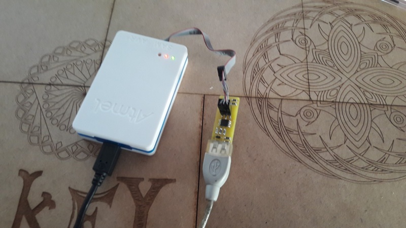
Red LED On!
Problems Faced!
In the beggining it was very hard to get the fab ISP recognized in my windows desktop.
Here's what i had to do:
Download the fabisp drivers
The programmer wasn't connected correctly (pin 1 on the connector matches up to pin 1 on the board)
Change the programmer name to atmelice_isp, othwerwise it will try to program through jtag
Run make rstdisbl to blow the reset fuse
FILES
Board Firmware
Board Vector File
Roland Modela Clearance File
Roland Modela Cuting File