As my experience in network communication was limited to the gestalt nodes example we managed to establish for the Machine Design assignment, I decided to start by setting the serial asynchronous communication between two boards, a bridge and a node. The next step would be to hack my step response board in order to achieve a third node response on my network.
Making the Boards
This step was pretty simple by following the schematic given for the bridge and the node. The two boards are completely the same apart from the bridge bearing the FTDI header.

Schematics and boards:
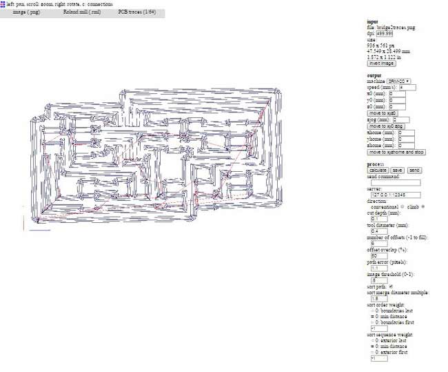
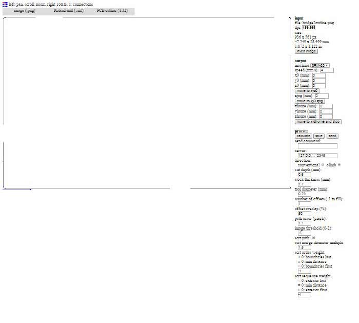
1.bridge
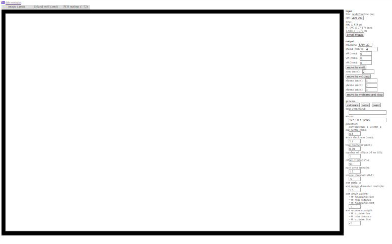
2.node
The files of the traces, outlines and .rml files can be found here. The milling settings I used are shown below.

After soldering my boards I checked for any bad connections with the multimeter. I soldered on my traces a bit, because I milled with a broken drill bit and I was not entirely happy with the results.

Programming the Network
Programming the first board : Node 0. For this purpose I used the FabISP and the bridge, both connected to the computer as shown in the picture.

Programming through the Command Prompt on Win7.
-- Enter the folder containing the .c and .make files.
-- use the command :
make -f 'makefilename' program-'programmer'
or: make -f hello.bus.45.make program-usbtiny

The programming of the first board was completed successfully. In order to program the second board I connected the boards as shown below, connecting the programmer straight to my node.

I removed the .hex and .out files from my .c and .make files folder and then edited the .c file, changing the node_id from "0" to "1".

I followed the same process in order to program my board as a node 1. In the beginning I kept on receiving "Error 1." I tried to program with the AVRdude in ordr to see if there was any problem with the FabISP. I did that by changing my command to:
make -f hello.bus.45.make program-avrisp2
I kept on receiving the same problem.

I knew it was a hardware problem se I went back and checked again my connections on the board between the headers and the microcontroller pins. I found a badly soldered pin and fixed it. I tried programming again and, thankfully, it worked!

The last step would be to check for responses. I used the Arduino IDE Serial Monitor. I disconnected the FabISP and connected the 4-pin headers of the boards with a ribbon cable and both to the computer throught the FTDI.
First, I set all the proper settings on the Arduino IDE
--ATtiny45 for the board,
--and the respective Serial Port (COM#)
and selected baudrate 9600 on the serial monitor window.
Typing 0 and 1 on the monitor, made the boards blink, the one I was adressing to, twice.

Video
The files of this assignment can be found here.