Inspiration
Assignments
- make a machine and end effector + build the passive parts and operate it manually + automate your machine
- document the group project and your individual contribution
- Automate your machine
This week is all about Machines and their Design. It's a group project so it's going to be an exciting week.
Between our group we made a brainstorm of possible machines we could build and the degree of axis freedom we would like to work with.
We ended deciding we would build a circuit drawing bot for kids and grownups. This was a great starting point and so we decided to divide our project into smaller and more manageable tasks :
- Xavi Dominguez - Programming
- Arnau Tàsies - Graphic Design and 3D Design of Drawbot 1.0
- Joe Galea - 3D Modelling and Extruder of Drawbot 2.0
- João Leão - Electronics and 3D Modelling of Drawbot 2.0
- Katerina Labrou - 3D modelling and Programming
Although we decided to divide the tasks we wanted to switch between each other so we could have an idea of the different work flows.
We are going to start by working in the given MTM Kits from Nadya and create a prototype of our desired goal so we can understand how the Nodes, Mechanics and Programming works. As soon as the prototype is well on it's way we are going start designing the Drawbot 2.0 and it's mechanics.
PICTURES:
As a starting point, we used the Rhino design files from Francesca Perona, you can download them here.
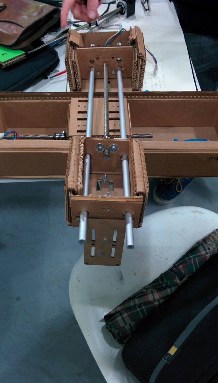
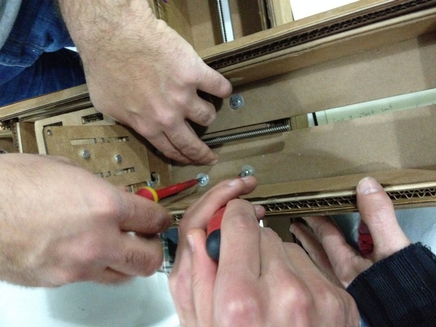
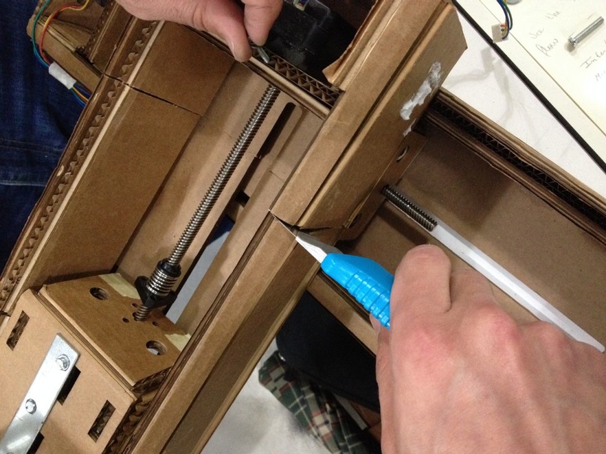
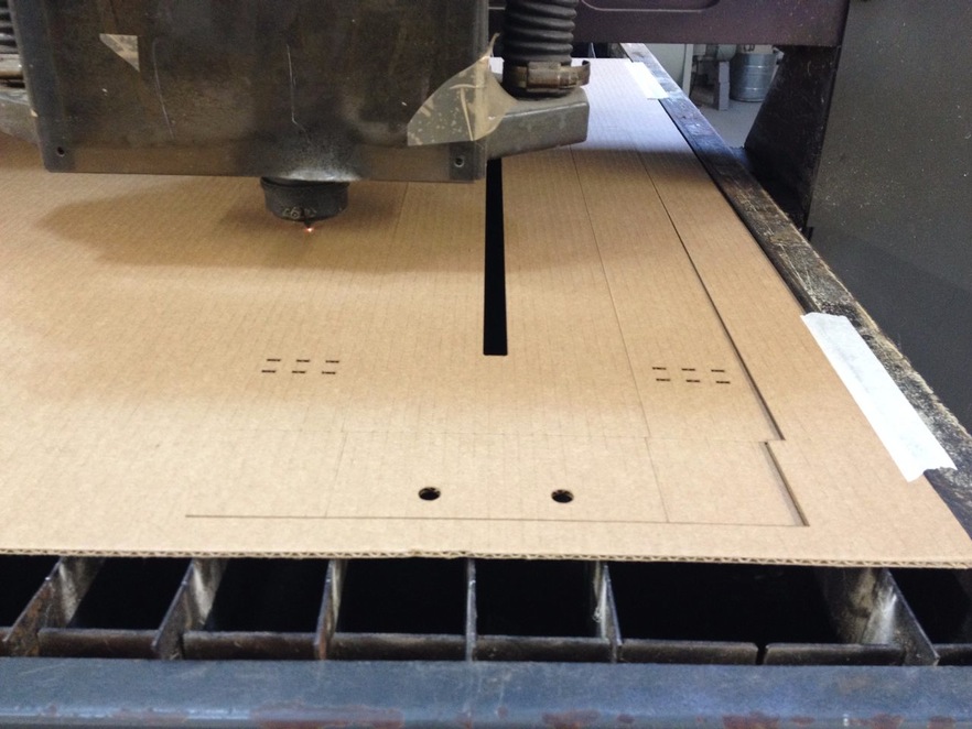
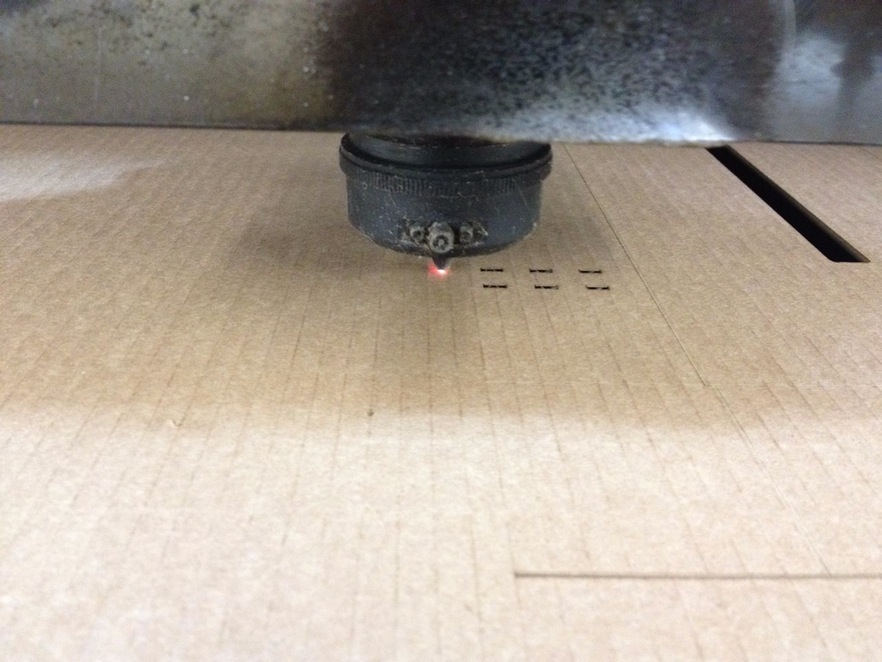
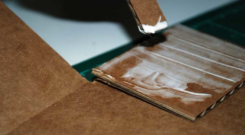
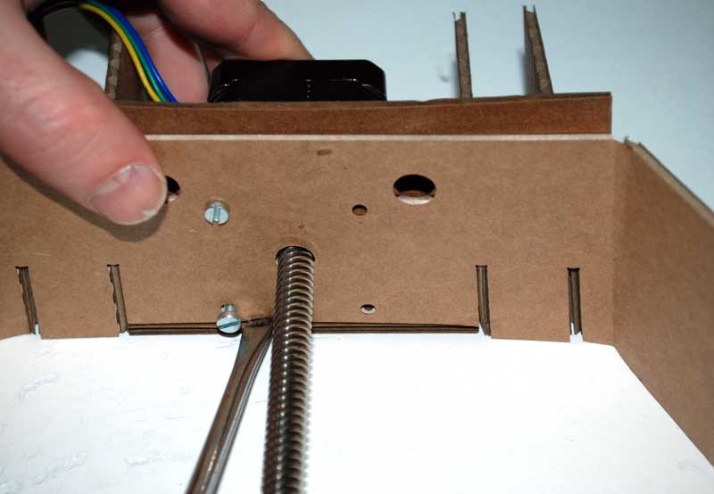
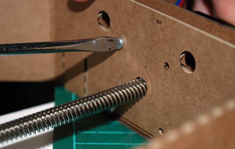
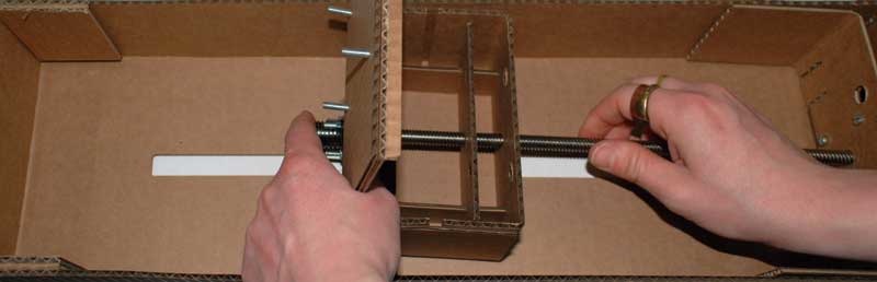
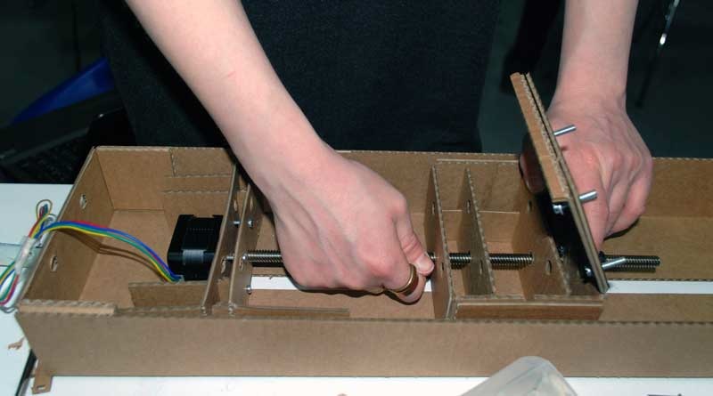
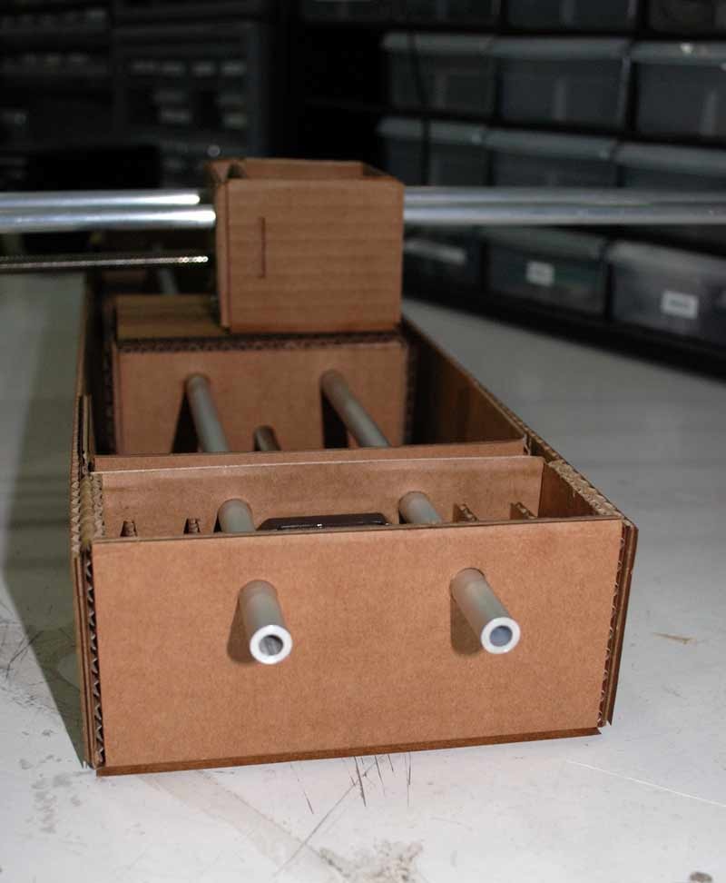
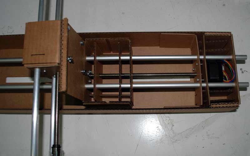
This is the process of building the first prototype.
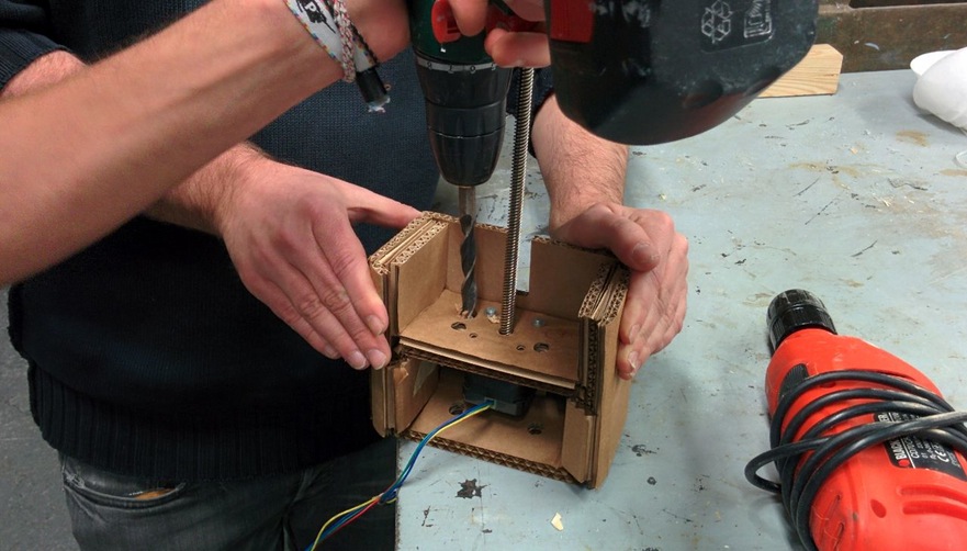
Design
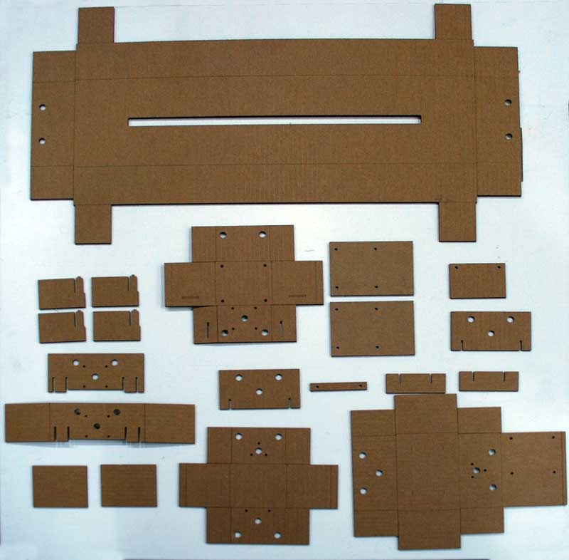
At this point we decided we should get rid off some of the cardboard, to make it fit to our design purposes.
With our prototype working we focused our efforts in making a brand new and different design.
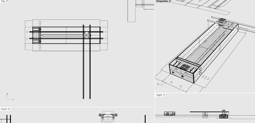
The next image is the original Rhino file from Francesca Perona, we decided to redraw the file, in order to make small changes on the design and end up with a lighter structure.
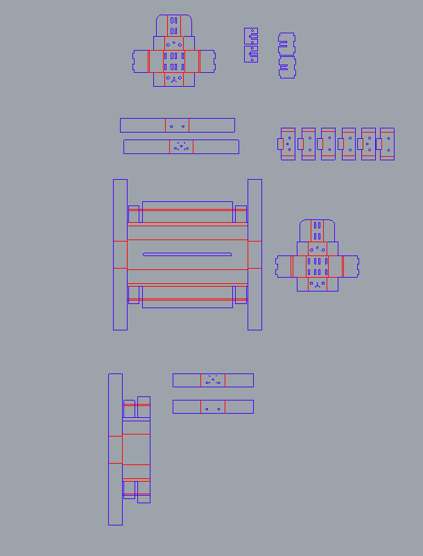
The next image shows a top view of the process of redrawing this files.
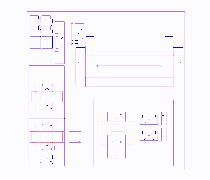
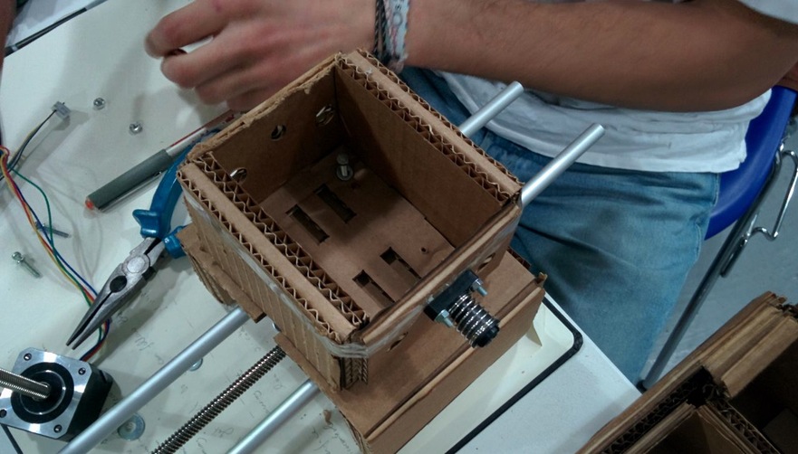
We intended to make the housing of the x,y axis lighter, adapt it to the 2mm cardboard we would use, and correct some details - such as the heights and sizes of the holes for the shafts and the screws.
Starting with building the 3D model of the axis, in order to visualize our parameters, we gradually build the outsides, and then moved on to the inside parts which will hold the motors and support the whole structure. The next images show the design in Rhino process.
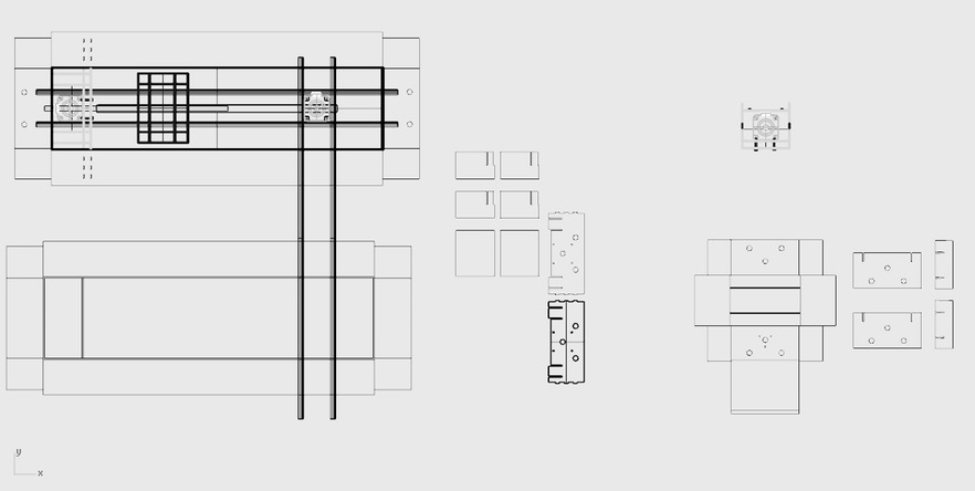
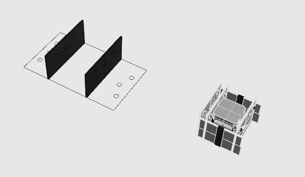
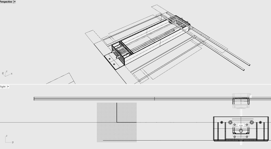
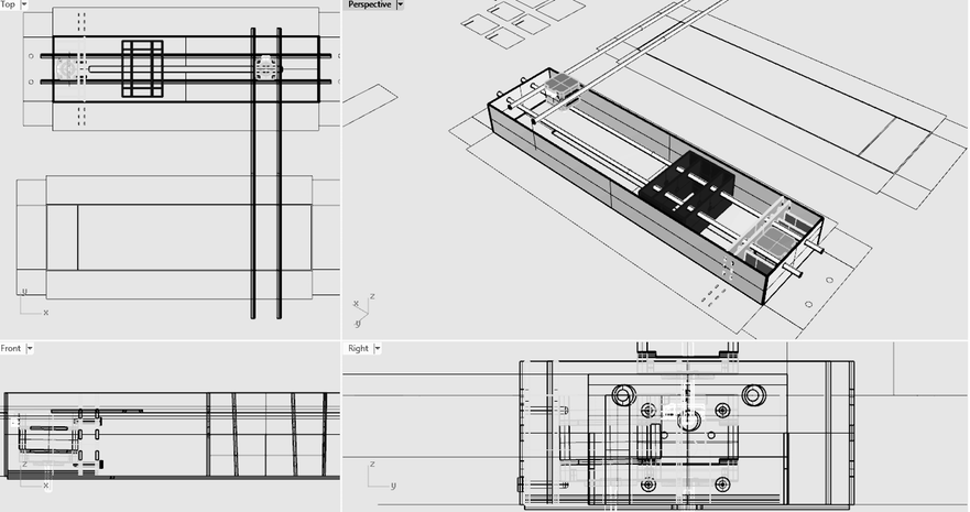
Having the 3D design of our machine made it easier to understand and troubleshoot the file for the laser-cut. At the same time, it is helpful in terms of optimizing the machine structure and parts for the following week.
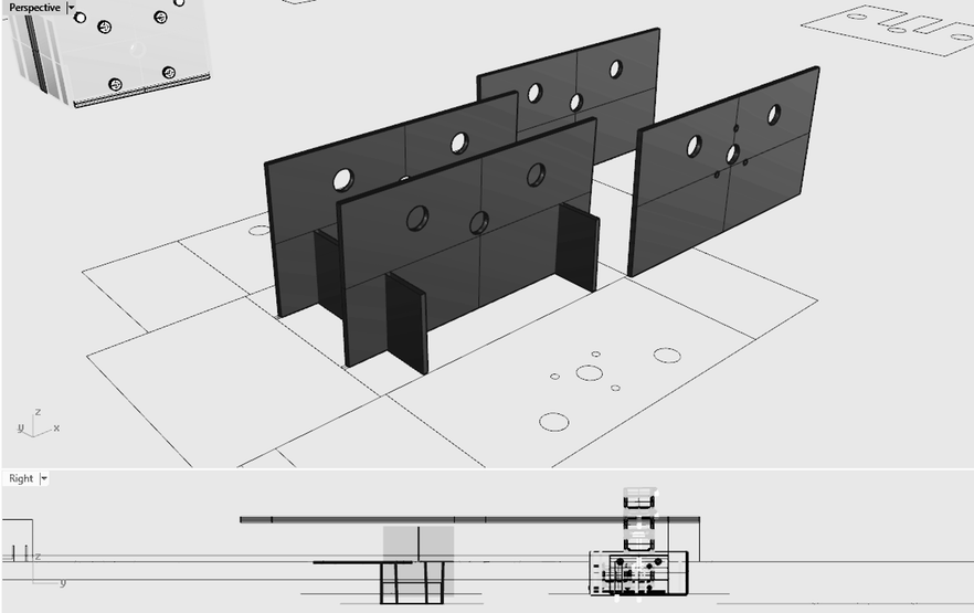
The next series of images show the process of building the 2nd prototype with the lighter housing.

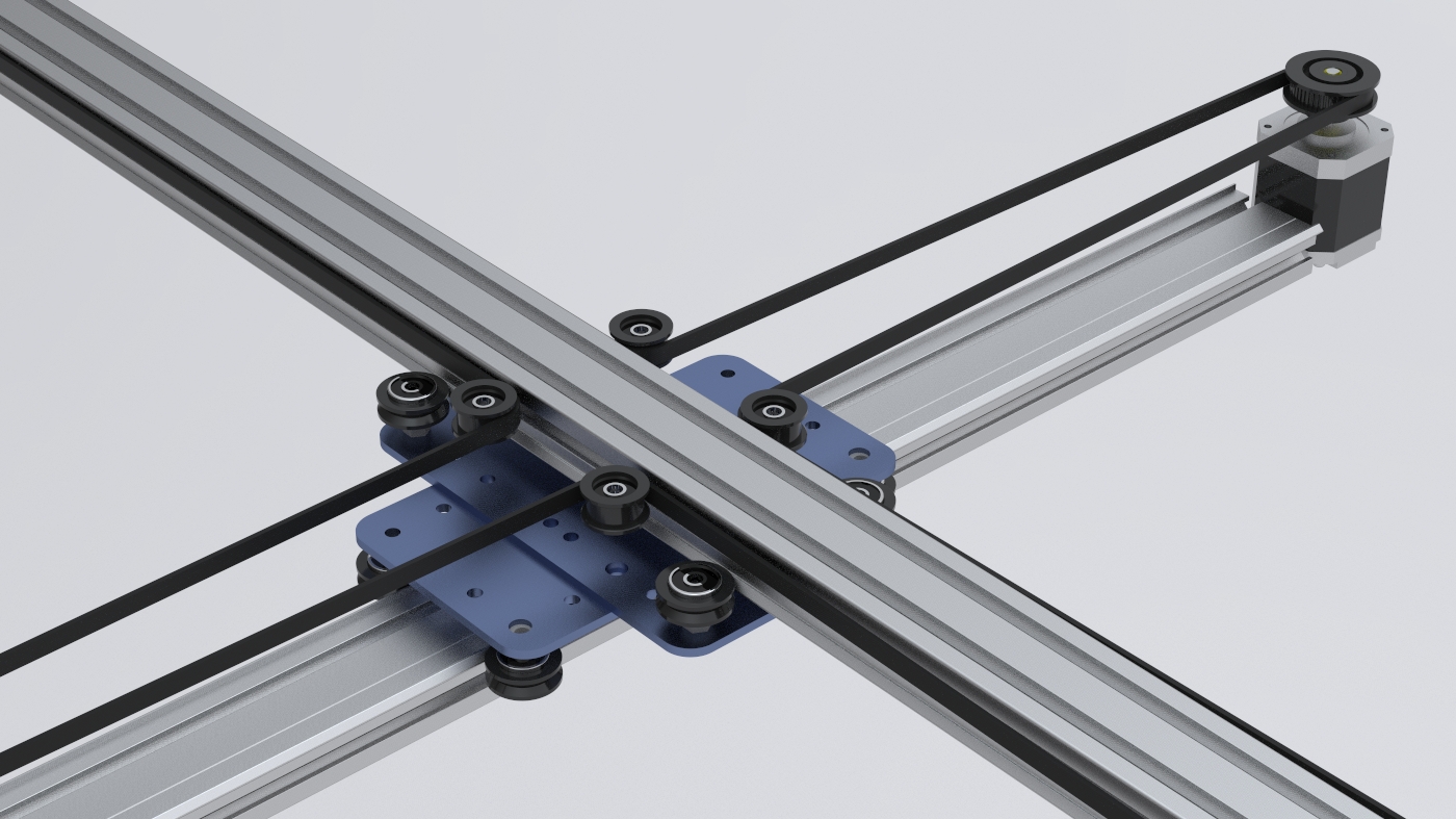
Mechanics
Interesting link about how to build an H-bot
H-bot link 1
Another interesting link
H-bot link 2
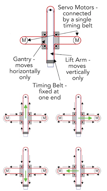
EQUATIONS OF MOTION
A,B: motors

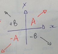
diaA =incX+incY
neg_diaA= -incX -incY
diaB=-incX+incY
neg_diaB=incX-inxY
Link about core xy theory
Another link about machining
BOM:
- 2-4 x Linear bearing LM10UU
- 2 x NEMA 17 Motors
- 1 x smaller NEMA motor for z-axis Robocraft datasheet link
- HPDE or Print in PLA/ABS
- 4 x Shaft's 9mm Diameter
- GT2 series belts
- 2 x GT3 20T 6.35mm (width 18.30mm) Motors
- 4 x 2mm 20T GT2 Pulleys Reprap choosing belts and pulleys link
Programming
If you are new in Python:
https://www.python.org/about/gettingstarted/
- 1. Download and install Python:
https://wiki.python.org/moin/BeginnersGuide/Download/
-tip-
you can download Python 3.x and/or 2.x ....install both versions and use the right interpreter depending of the project.
IMPORTANT!
pyGestalt only works with Python 2.x so for that project use it! - 2. Download Python IDE or Python interpreter:
Options: https://wiki.python.org/moin/IntegratedDevelopmentEnvironments
Xavi election: http://www.jetbrains.com/pycharm/
Interpreter: https://www.python.org/downloads/
- 3. Getting started
-tutorials for beginners-
http://pythonprogramminglanguage.com/
Python interptreter VS Python IDE (PyCharm). The interpreter is the command line in the Terminal. You can use it for programming. The PyCharm is an IDE for programming: supports listing all program files, syntax highlighting and other features.
http://wiki.evilmadscientist.com/StippleGen
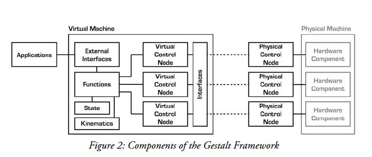
Gestalt Framework:
http://pygestalt.org/
https://github.com/nadya/pygestalt ( github )
Student reference:
http://fabacademy.org/archives/2015/eu/students/hisatsune.taichi/classes16.html
Step by step:
Good guide:
http://fabacademy.org/archives/2015/doc/MachineMakingNotes.html
-
1. Download pyGestalt Framework and install it.
https://github.com/nadya/pygestalt/archive/master.zip
--> in the directory where setup.py is:
sudo python ./setup.py install
-
2. Programming the Gestalt Node with and AVR.
Why? -> The Fabnet to node connector is not typical!
-> Are nodes already programmed? Yes, we have it.
-
3. Download and Install pyserial -> order to talk over serial
-pySerial is a module to communicate python with the serial port ( Python Serial Port Extension ).
download from here:
https://pypi.python.org/pypi/pyserial installation guide:
http://pyserial.readthedocs.org/en/latest/pyserial.html#installation sudo python ./setup.py install
- pySerial Documentation:
http://pyserial.readthedocs.org/en/latest/index.html
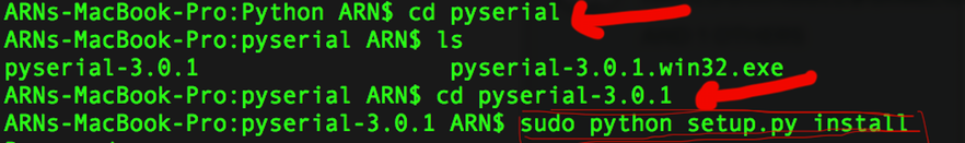
On Mac Os installing PySerial & pyGestalt from the Terminal:
- 1. Download and extract pyserial.
- 2. Navigate via Terminal to the folder you have pyserial extracted, in this folder you should have a file called setup.py
- 3. Run this script
sudo python setup.py install
At the end of installation you should get a message like this:
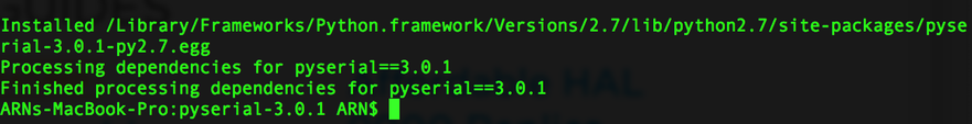
A similar process should be done for the pyGestalt
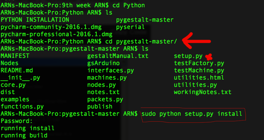
- 1. Download the Nadia Peek pyGestalt framework.
- 2. Navigate in the command line where your pyGestalt folder is located.
- 3. Run the command: sudo python setup.py install.
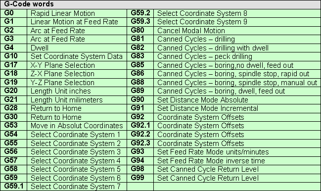
* Generate GCode:
Main g-code commands:
Commands for the XYCore Mechanics
http://www.schmalzhaus.com/EBB/EBBCommands.html
RoboPaint
Software for drawing robots
https://github.com/evil-mad/robopaint
Firmware used in a similar machine
http://wiki.evilmadscientist.com/WaterColorBot_Reference_Design
Arduino 2 axis G-code Interpreter
https://www.marginallyclever.com/2013/08/how-to-build-an-2-axis-arduino-cnc-gcode-interpreter/
PNG -> GCODE
- G-code is a language in which people tell computerized machine tools how to make something. The "how" is defined by instructions on where to move, how fast to move, and what path to move.
- https://en.wikipedia.org/wiki/G-code#Specific_codes
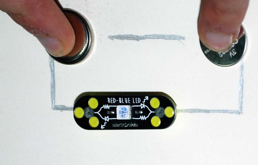
Conductive Ink
First we got some comercial conductive ink. Here you can see how we were trying it:
The first step was to look for documentation and tutorials on how to make your own conductive ink.
http://www.instructables.com/id/1-DIY-Conductive-Ink/?ALLSTEPS
https://www.youtube.com/watch?v=W_ouYLeIkoo
- Glue
- Charcoal (Braseria)
- Black Ink
- Pen: http://www.electroninks.com/ ->arrives on wednesday (6th April)
- Carchoal: less resistant better (<200 Ohms)
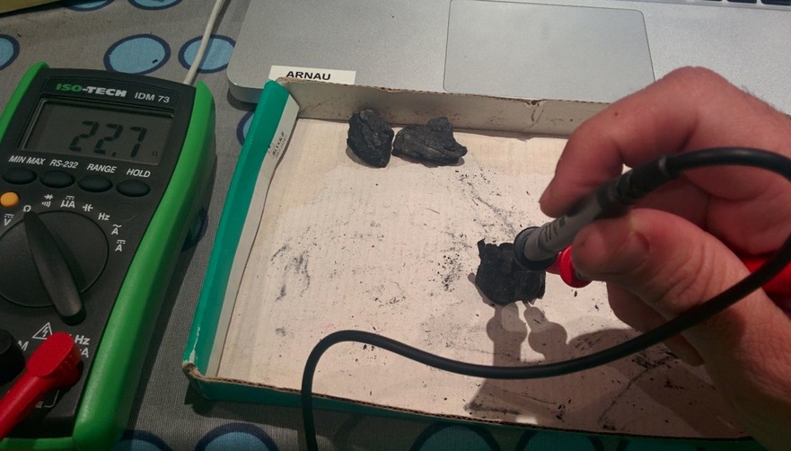
Testing the conductivity of the charcoal.
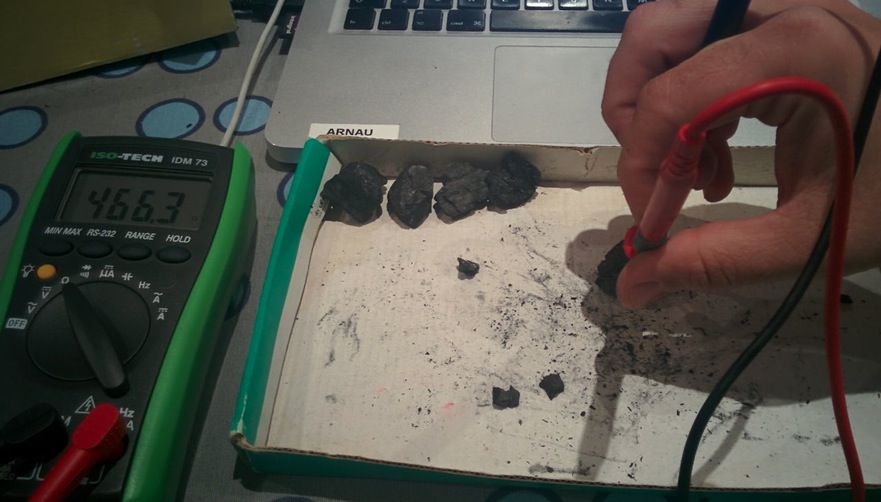
Making more tests...
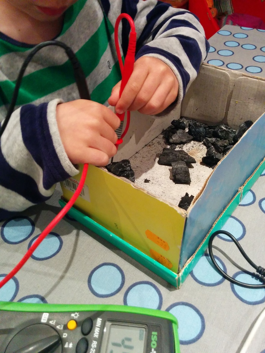
Even Xavi's kids were curious about it...
Mixing the ingredients to develop the material:
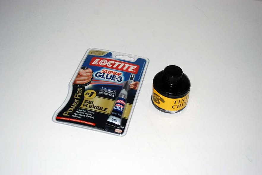
The other "ingredients": cyanoacrylate (Super Glue) and India ink.
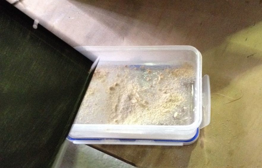
The tuperware is full of charcoal dust.
Mixing it all together with the charcoal.
Adding some water and more glue.
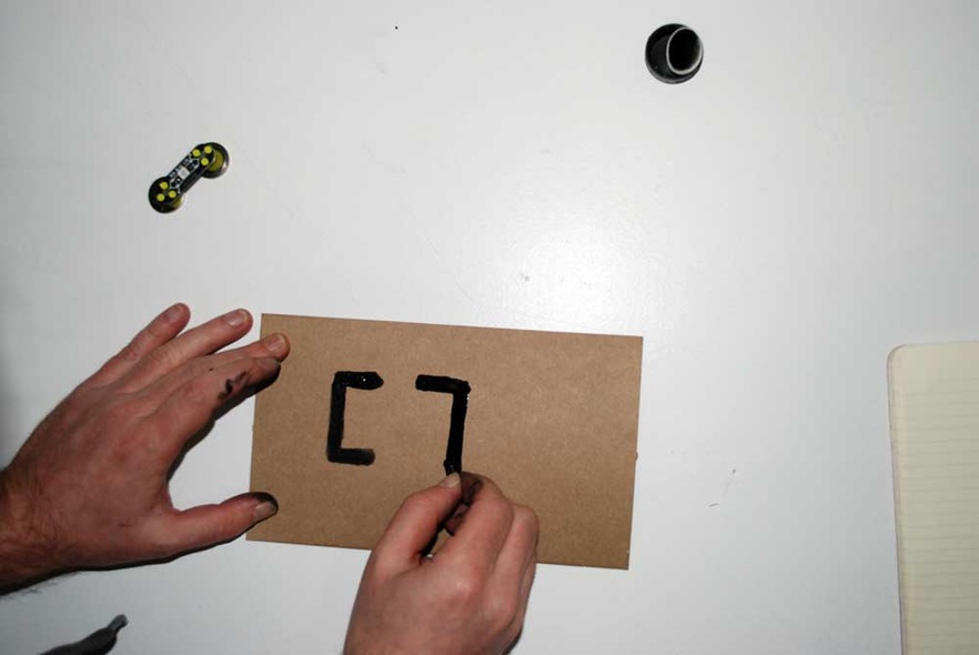
Drawing the circuit in the cardboard.
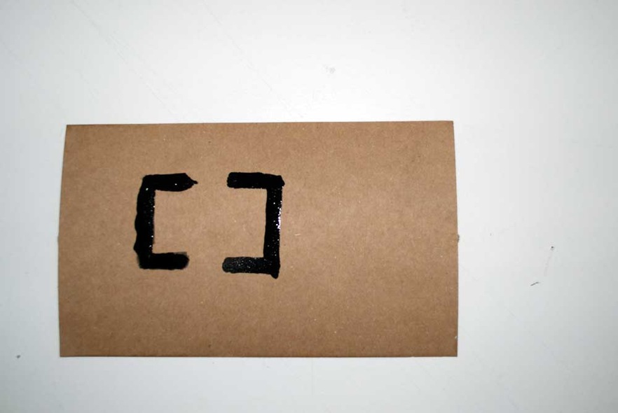
Our final circuit.
Testing the circuit.
Conclusions:
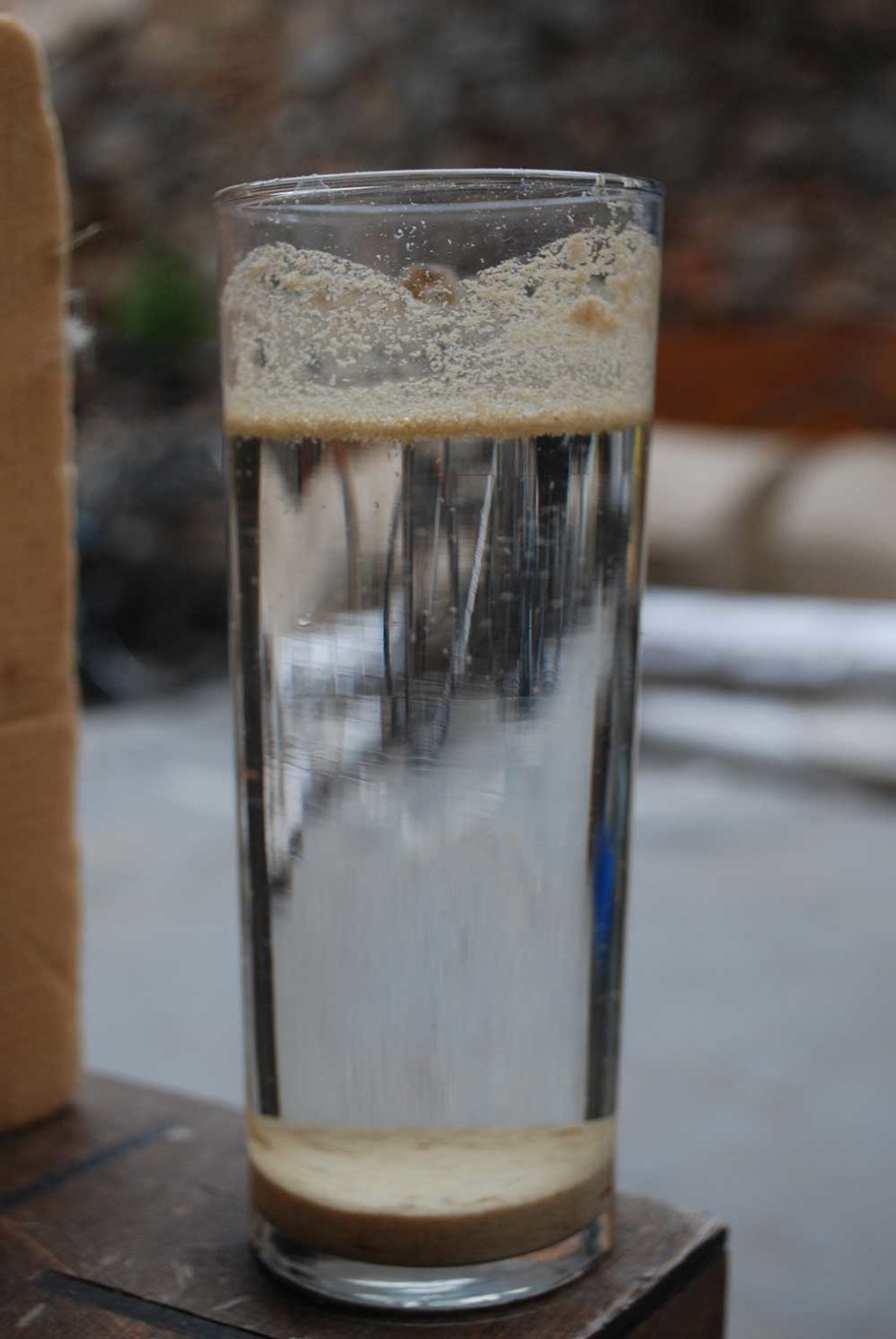
We decided to use the copper dust from the Roland milling machines to add copper dust to our ink.
Using water we can get rid off the fiber glass (floating material), and separate it from the copper dust (drown material).
We still don't know if it will work... Let's see what happens :)
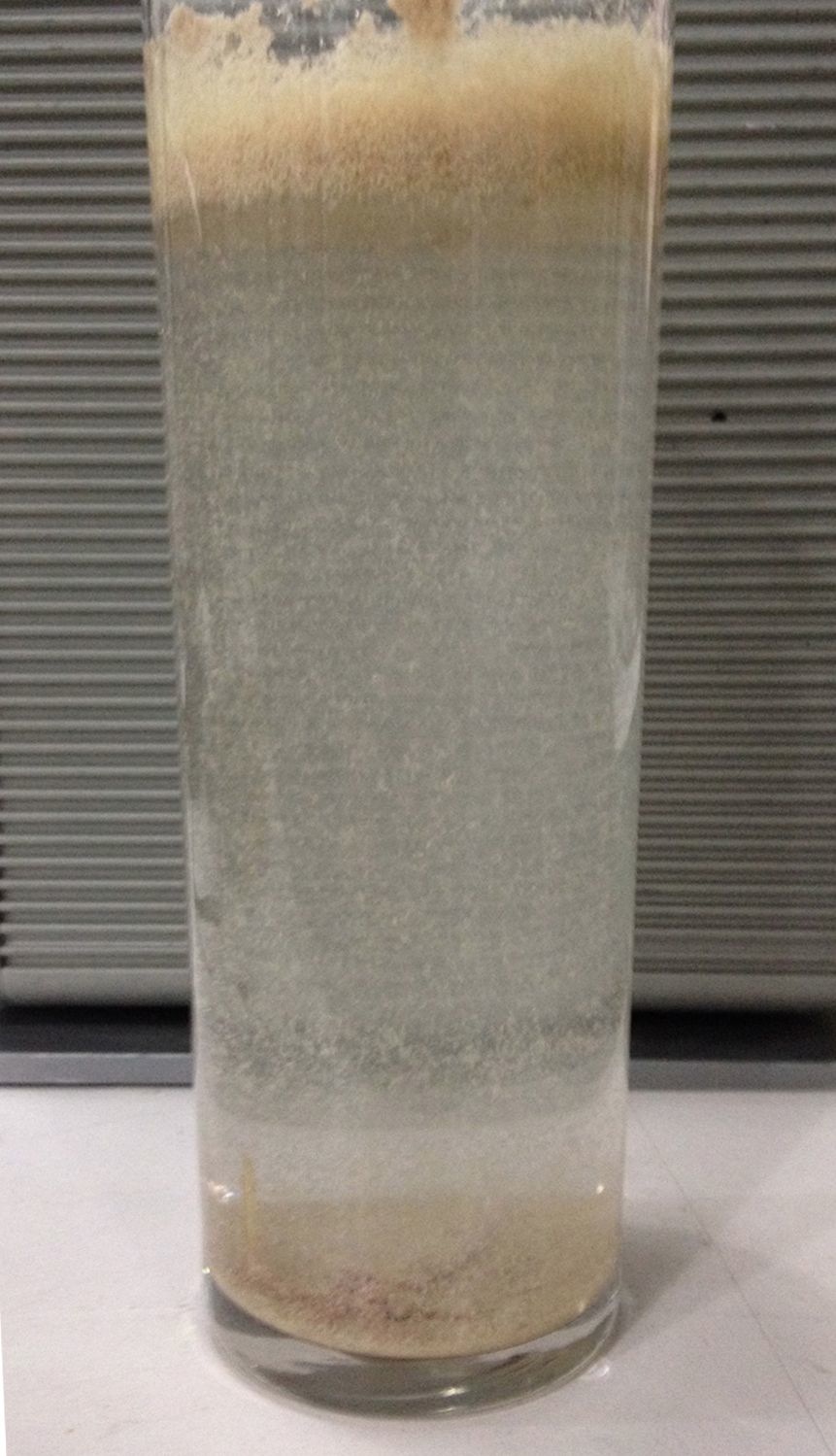
The result of our experiment was not as expected; even though fiberglass parts elevated to the surface of the glass, we got a mixture of copper and fiberglass at the bottom. Therefore, we have to figure out another way extract our copper filings.
Electronics
http://fabacademy.org/archives/2015/doc/MachineMakingNotes.html
Motor Board files:
https://github.com/nadya/MTM-Snap-Shield
https://github.com/imoyer/086-005
Motor Board used in Axibot:
http://www.schmalzhaus.com/EBB/
Hardware:
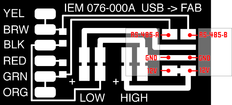
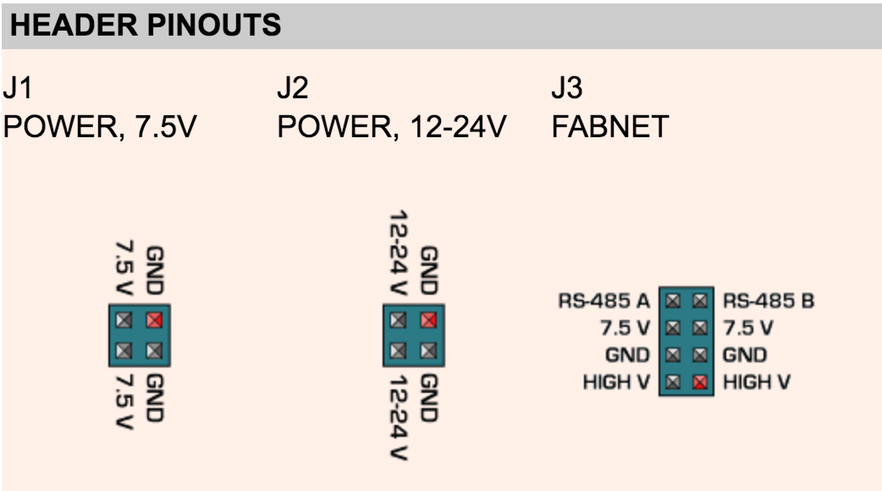
For the electronics, we need to mill the FabNET board to use it with RS-485 usb connectors
Fabnet is a multi-drop network, meaning that multiple modules (a.k.a. nodes) share a single set of communication wires. Signalling is differential based on the RS-485 specification. Each node is assigned a four-byte IP address which uniquely identifies it over the network.
Fabnet provides power at two voltages: high voltage (12V - 24V) is intended to drive motors, lamps and actuators, while low voltage (7.5V) supplies power to the logic circuits of the nodes.
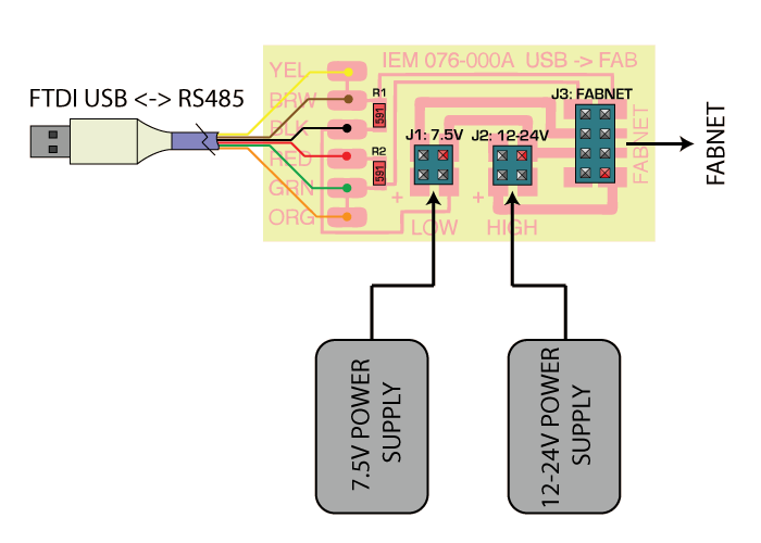
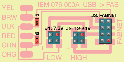
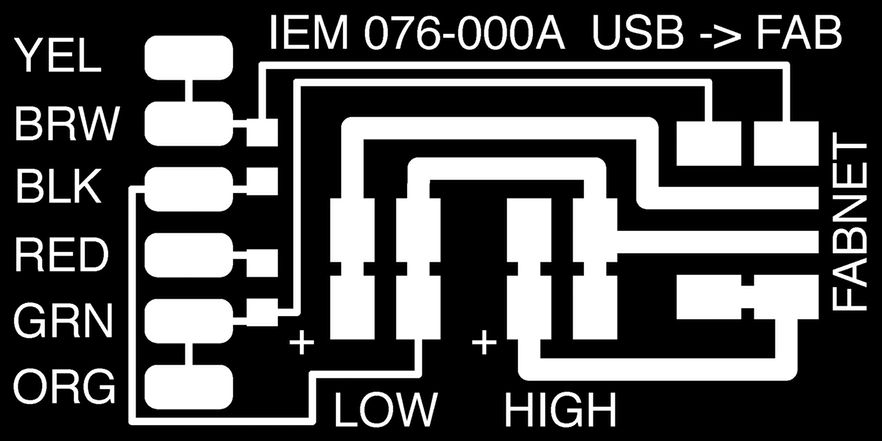
Establishing connectivity between nodes and a computer, and providing proper power, requires several components: high and low voltage power supplies, a USB-RS485 converter cable, and an adaptor board (076-000A) with bias resistors.
The next images are some diagrams to understand how the FabNET connects to Gestalt boards and power supply.
http://mtm.cba.mit.edu/machines/stages/
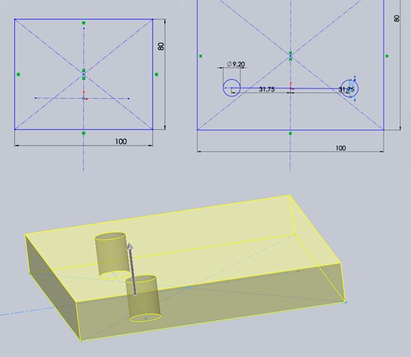
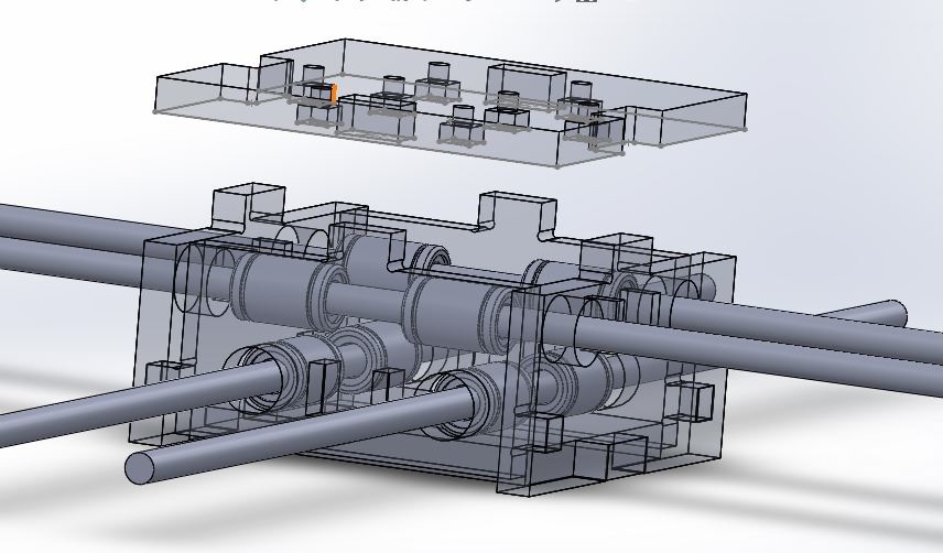
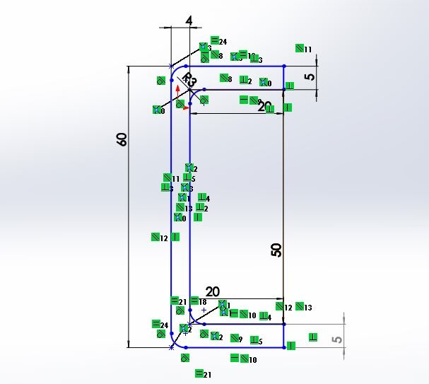
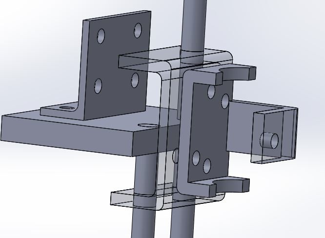
On doing the new version we used the HDPE version of the MTM to base our 3D model and re-design the mechanical system. We downloaded some pre-made SW files of the motor and the pulleys we were going to use so we could aligned all the parts perfectly..
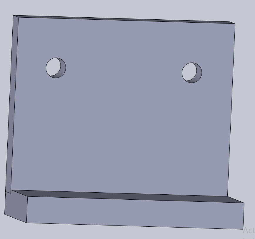
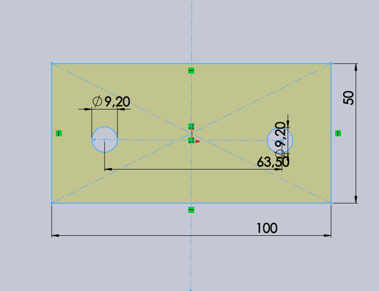
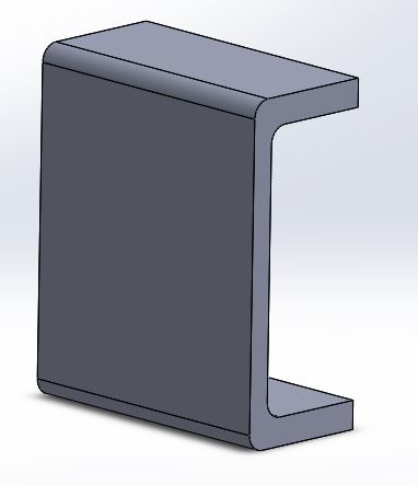
Sideboards stands
For supporting the whole structure. We need this pieces as part of the base.
We will be using a Counterweight. This is just a square piece of plastic in the opposite side of the pen handler.
An approach to the handler design.
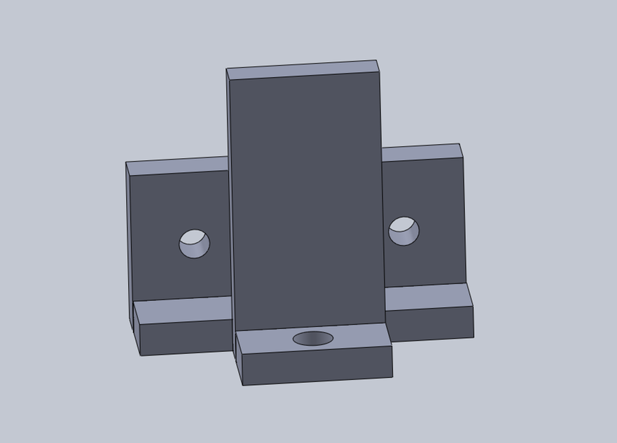
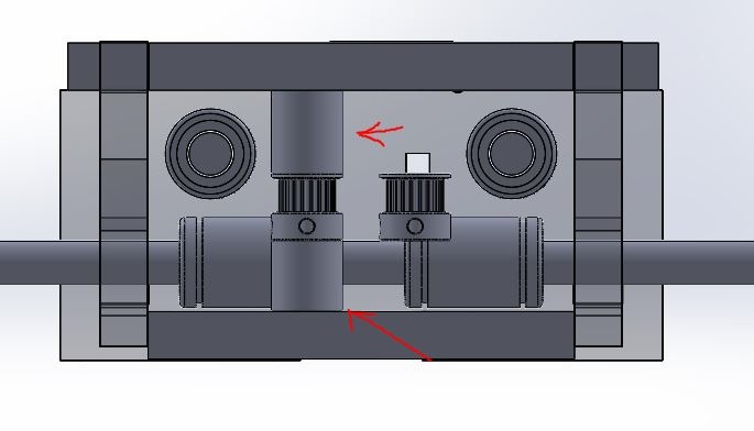
Central Design
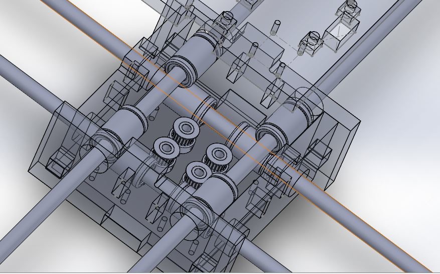
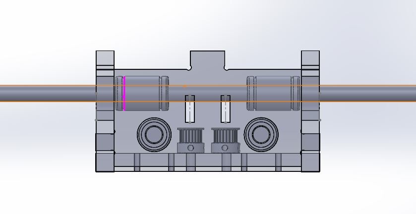
Solution to support the central pulleys
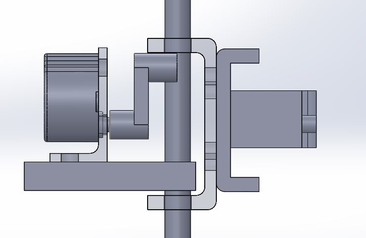
Head Design
Regarding the handling pen.
Our reference project, AxiDraw uses a complex system with a servo motor. As the pictures below:
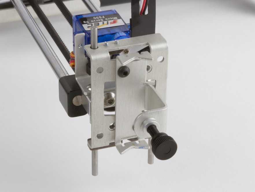
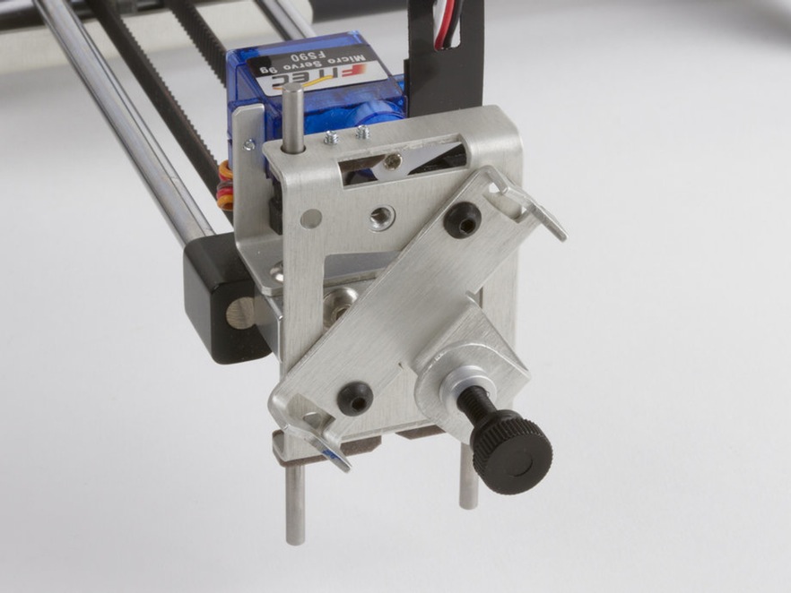
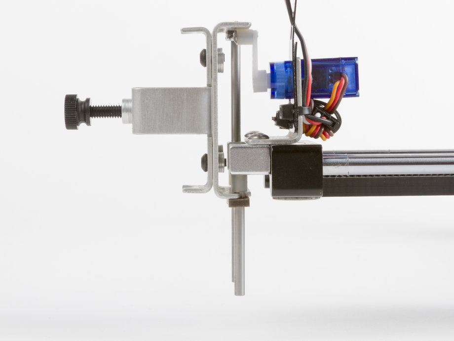
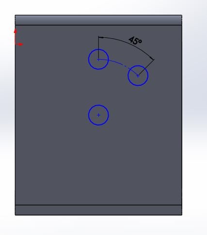
We are designing a handler with two different positions depending on how we want to position the pen: perpendicular or oblique in relation to the surface we are painting.
Some pens need a angle to draw so we are using a screwing system to change the angle of the pen holder instead of making it autonomous which would make the programming even more complex.
Digital animation made in Solidworks of the machine working:
A simulation with the pen holder working:
The machine working!!
Finally just point out that for this assigment my focus areas has been the 3D design process and assembling the two versions of the machine.
But I, also, felt really interested by the programming area led by my classmate Xavi Dominguez.
The files for this assignment can be found here.