This week's assignment is to make a pcb using a sensor and program it in order to get an input that can be visualised.
Going through the list of sensors I decided that I wanted to make a touchpad. I was really interested in making something like Matt Blackshaw's Touchpad.
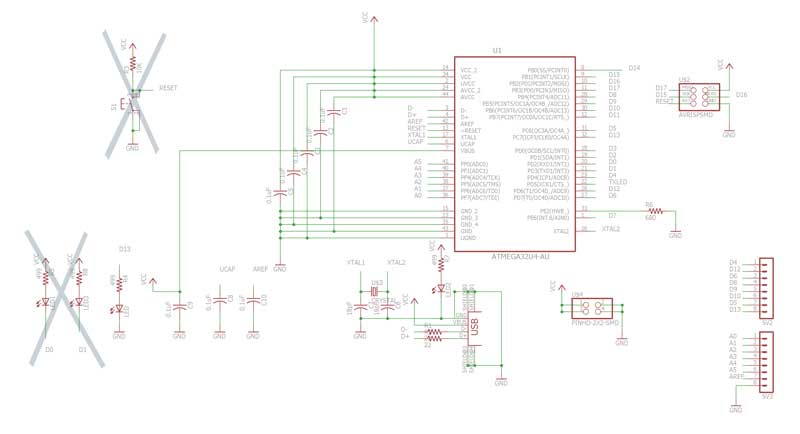
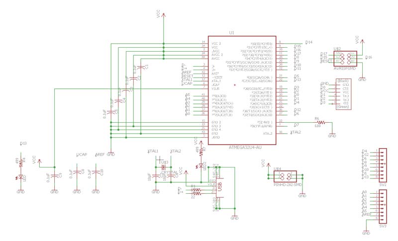
At the same time, I wanted to invest my time on making a design for diverse applications, which I could probably use for my Outputs week assignment. Soon I found the schematic and board design for FABLEO, which uses the ATmega32u4 microcontroller, same as the Arduino Leonardo. ATmega32u4 has built in USB communication. Having no intermediate chip, it has bigger data buffers than the serial port, therefore it must be quite fast in processing serial data. Starting from the given schematic, I redesigned the board.
Board Design Process.
Initial schematic and FABLEO board. While redesigning the board, I took out two LEDs and the Reset button, in order to reduce it in size.
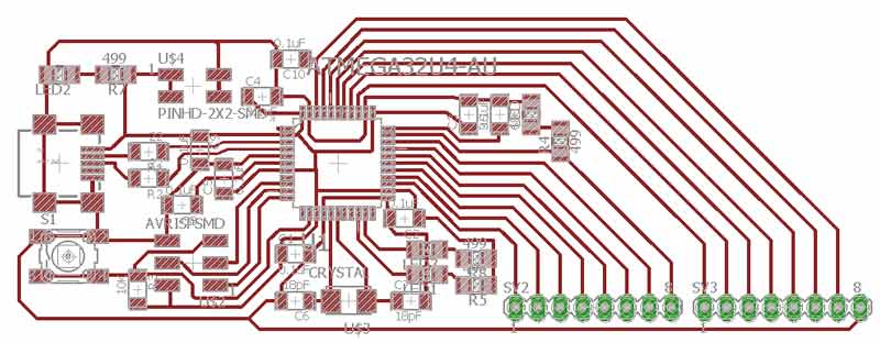
Also, I came up with a circular design.
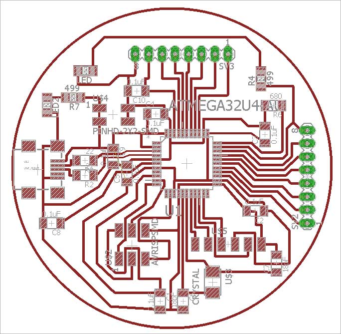
In order to mill the circular board I created the traces and outline as shown below, so that the surrounding square parts would be directly removed while milling the outline.
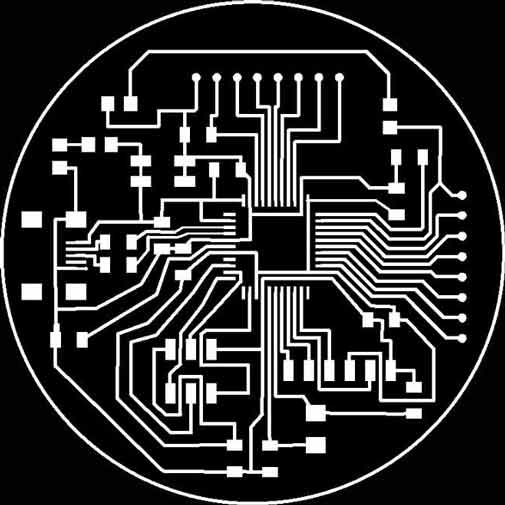

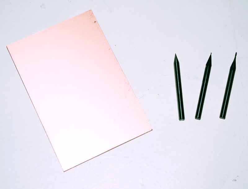
Milling the board.
The ATmega32u4 microcontroller has 44 tiny "legs," and Fabduino in quite a loaded board. I run 2 processes as usual, but my result was not good enough. For this reason after running the 1/64 process for a second time, I tried using the 0.01 drill bit in order to get a better milling resolution and clean the parts between my traces between running the 1/32 process of the outline.
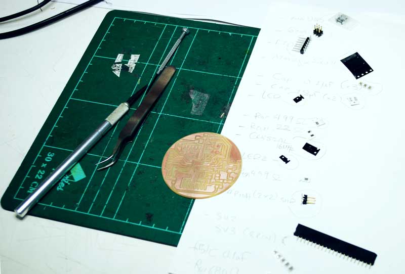
Components to solder:
--ATmega32u4 microcontroller
--mini USB header
--FTDI header
--6-pin header (3x2)
--4-pin header (2x2)
--8-pin female headers (x2)
--0.1μF capacitors (x6)
--18pF capacitors (x2)
--499Ω resistors (x2)
--22Ω resistors (x2)
--680Ω resistor
--16MHz crystal
--smd LEDs (x2)
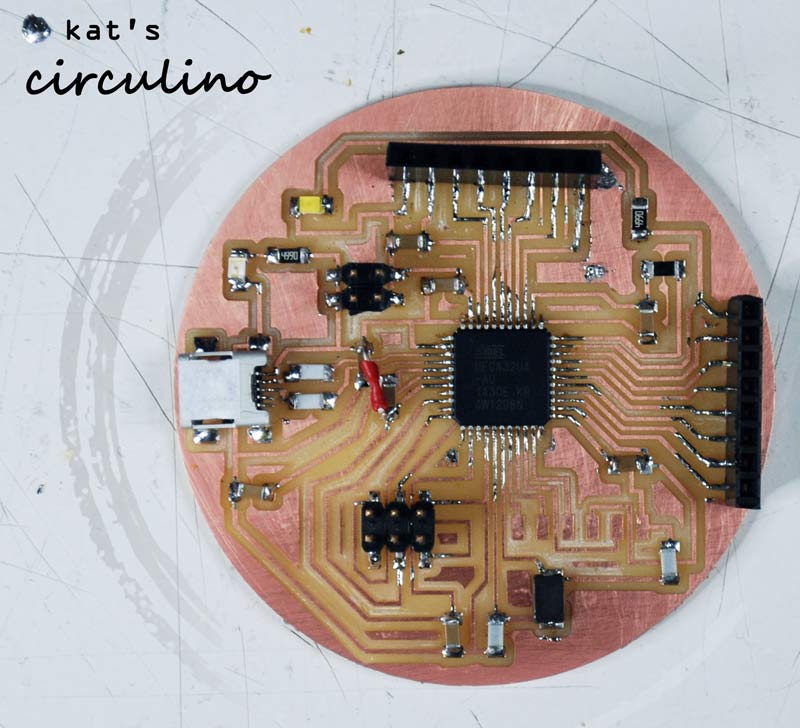
Programming the Circulino
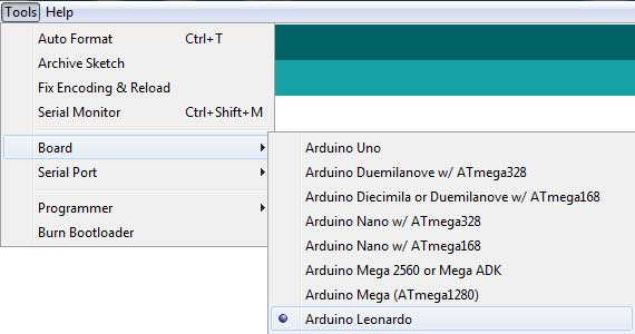
Programming the ATmega32u4, supposedly, is an easy task to perform, as it can be done through the Arduino IDE, by selecting the Arduino Leonardo on the boards panel.
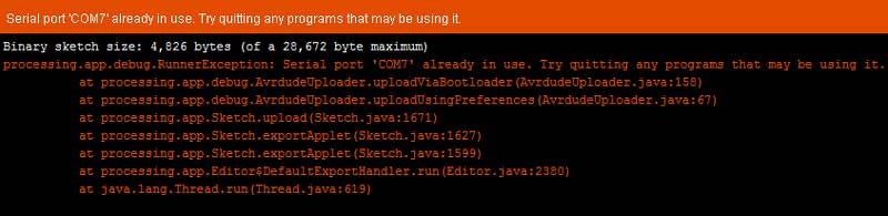
At the beginning I used the FabISP for this purpose but I couldn't make it work. I kept on trying to Burn the Bootloader but I was receiving the following error:
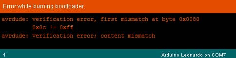
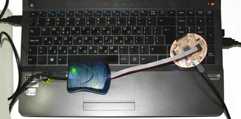
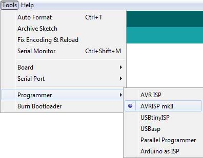
For this reason, after several tries, I used the AvrISP.
In this case, I received a different error, which I considered to be quite a hopeful message:
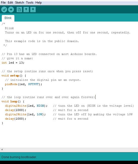
I unplugged the cables, reconnected them and successfully burnt the bootloader. Then, I loaded the "Blink" Arduino example, changing the delay between 200-1000ms and enjoyed watching my board responding to my commands!
The next thing I tried to do, was to figure out the way to connect it with Processing, so that I was able to interface with my inputs.
The first example I followed is nicely documented in this sparkfun tutorial.
A second tutorial I found on Arduino playground website uses Processing library for Arduino and Processing serial library.
Further documentation on interfacing with Arduino and Processing can be found in my Interface and Application Programming assignment.
~~~~~~~~~~~~~~~~~~~~~~~~~~~~~~~~~~~~~~~~~~~~~~~~~~~~~~~
** Reflecting on the design...
Although designing the circular board helped me improve in board design, after using the board for some time, I come to the conclusion it would have been better if I had left the RESET button of the initial design. The existance of the button makes it a lot easier coping with loading bugs of arduino boards, whereas I could only deal with them by pluging and un-plugging the USB cable. Moreover, I wish I'd kept the linear design of the 2 8-pin headers, as, with my design, I was no longer able to use the ready made Arduino shields.
~~~~~~~~~~~~~~~~~~~~~~~~~~~~~~~~~~~~~~~~~~~~~~~~~~~~~~~
Designing the Step-Response Board
The next thing I wanted to do is understand how the step-response input works. For this reason I designed the transmit-receive board and programmed it. My next step would be to try and debug the program in order to replicate it with my Fabduino or figure out a way to load it from the Arduino IDE to my ATmega32u4 microcontroller.
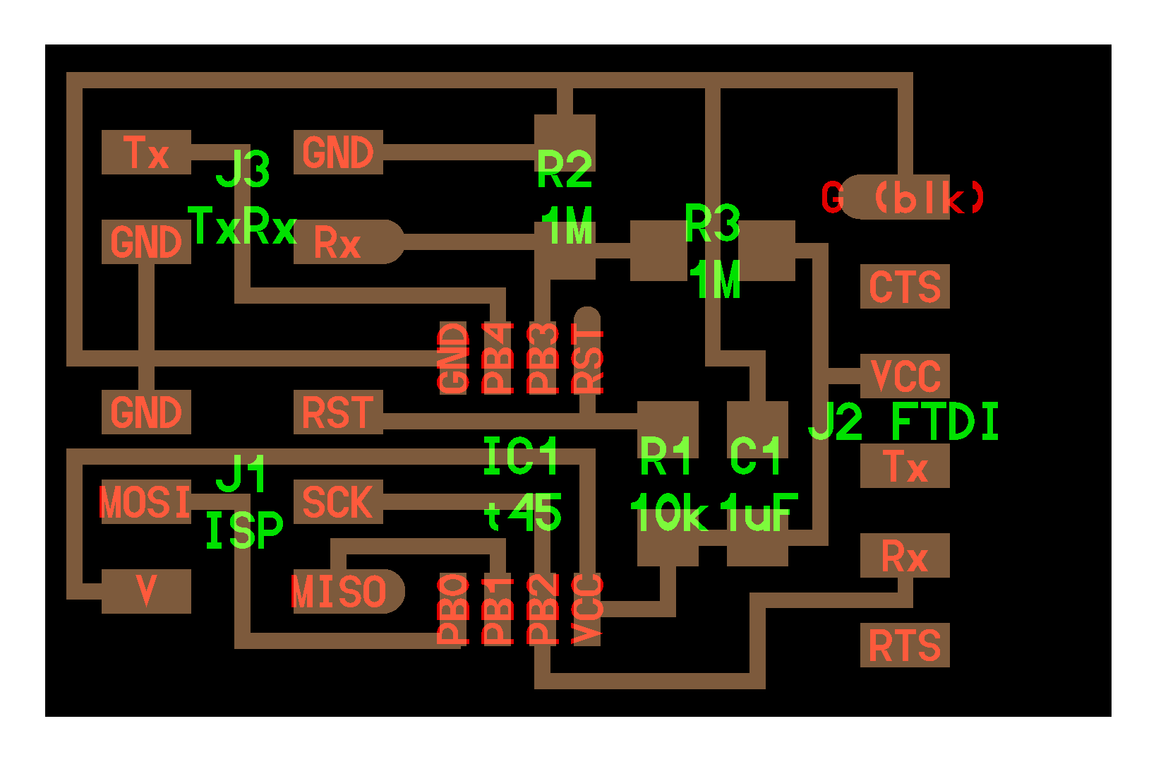
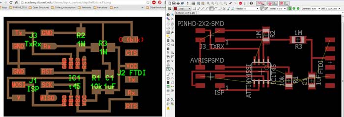
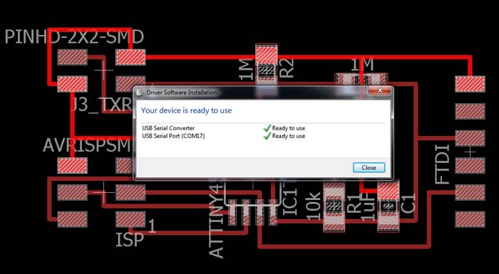
First, I re-designed the board on Eagle.
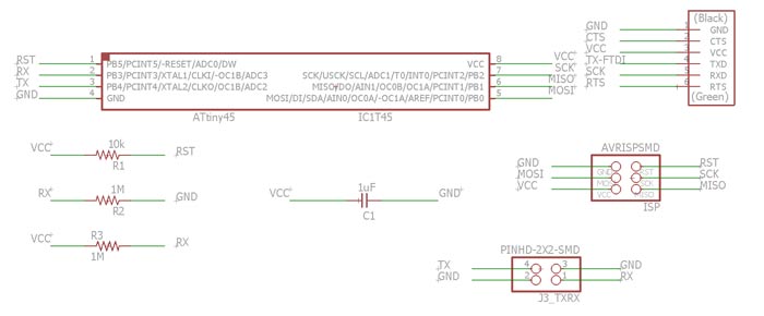
Given board vs. my board:
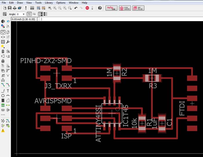
Board components:
--ATtiny 45 microcontroller
--FTDI header
--6-pin header (3x2)
--4-pin header (2x2) / TxRx
--0.1μF capacitor
--1MΩ resistor (x2)
--10kΩ resistor
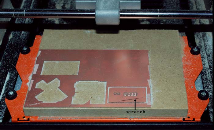
Milling the board.
For doing so, I created the standard two processes on FabModules, for the 1/64 and 1/32 drill bits.
I designed two separate pieces For the Tx-Rx inputs which would adapt to the respective pins on my board's 4-pin header.
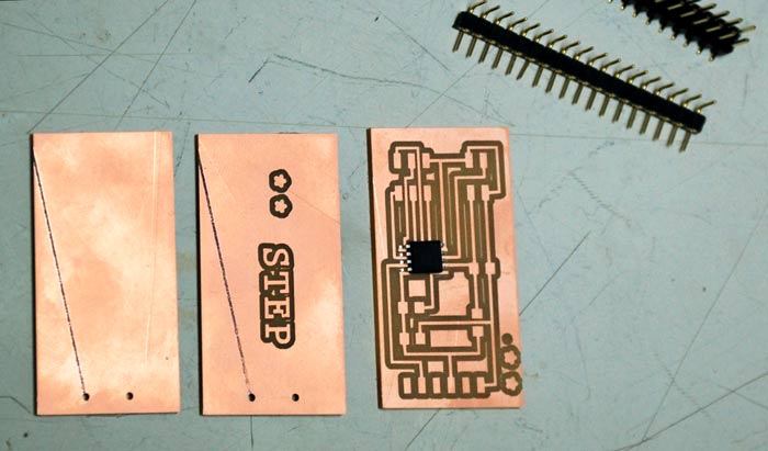
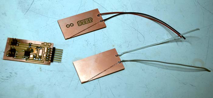
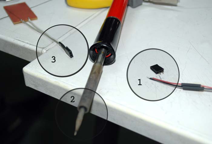
For connecting the electrodes I soldered two cables to each copper piece and then connected the female headers to the cables (1) by putting some solder on each cable and the soldering iron (2) and then holding the cables and the headers on top of it in order to connect as shown in the image (3).
This was my first attempt to solder components together not connected to a board.
Programming
The next steps were:
--program the avr with my FabISP / with the makefile and .c file I programed it to receive and process the sensing input
--loaded the the step-response python visualisation code
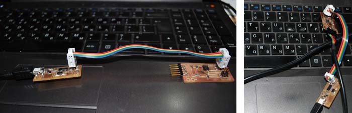
I checked for the GND and connected the FabISP, then through miniUSB and an FTDI cable to my laptop.
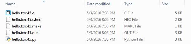
I used the .c and .make files for programming and runing the makefile the .out and .hex files were created. The .py is used for the inteface.
~~~~~~~~~~~~~~~~~~~~~~~~~~~~~~~~~~~~~~~~~~~~~~~~~~~~~~~
The makefile

~~~~~~~~~~~~~~~~~~~~~~~~~~~~~~~~~~~~~~~~~~~~~~~~~~~~~~~
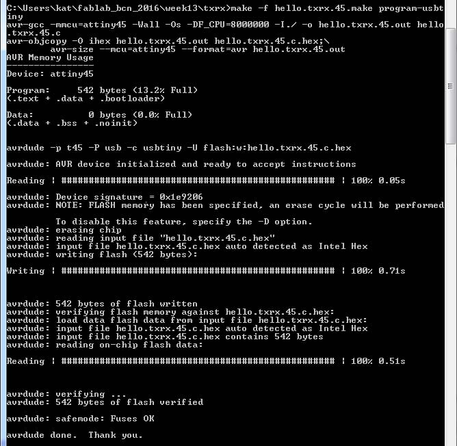
Through the command prompt, cd to the folder of the files.
-f hello.txrx.45.make program-usbtiny
(specify the file and programmer)
Load Python Interface
python hello.txrx.45.py COM17
(specify py.file and serial port of the step response board)
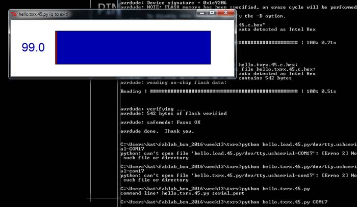
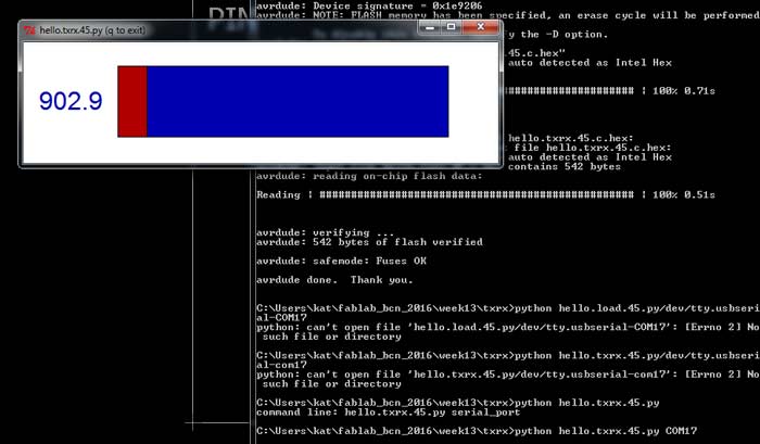
The values given and the visualization on the interface differed significantly when touching the txrx header directly, connecting a single electrode to vcc-gnd or connecting both and changing the capacitance by touching them.
Step-Response for the FABLEO
After sucessfully completing these tasks, I dived into avr programming in order to figure out the options for getting the same results using the Ardiuno.
I started by going through the .py code in order to understand it and see if I could possibly translate the processes in arduino code. Soon, I realized it was extremely difficult for a coding beginner like me.
I decided to use the Arduino Capacitive Sensing Library.
I followed the tutorial, read and understood the library commands, downloaded and loaded the library on my Arduino IDE.

I connected one of my electrodes to my Circulino on pin A3 directly and other one to pin A5 through a 10MΩ resistor.
Then, I used the CapacitiveSensorSketch Example and changed it. I ended up with the simple code below.
                        #include < CapacitiveSensor.h >

                        CapacitiveSensor   cs_5_3 = CapacitiveSensor(A5, A3);        // 10 megohm resistor between pins A5 and A3, pin A3 is sensor pin

                        void setup()
                        {

                           cs_5_3.set_CS_AutocaL_Millis(0xFFFFFFFF);     // turn off CALIBRATION
                           Serial.begin(9600);

                        }

                        void loop()
                        {
                            long start = millis();
                            long total =  cs_5_3.capacitiveSensor(30); //Sensor resolution is set to 30

                            Serial.print(millis() - start);        // check on performance in milliseconds
                            Serial.print("\t");                    // tab character for debug window spacing
                            Serial.println(total);                  // print sensor output 1


                            delay(1000);                            // arbitrary delay to limit data to serial port
                        }
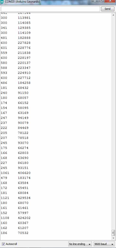
In the serial monitor I got one column stating the time intervals and another with the sensor values. I could change the values either by changing the resistor value on my circuit (higher resistance = higher sensitivity) or the resolution value (cs_5_3.capacitiveSensor(x)).
All the files for this week's assignment can be found here.