The goal for this week was to create an interface for one of our boards.
I chose to create a Processing interface through which I could control my LED arrayi plugged on my Circulino.
On the previous Output assignment, I posted the code for controlling the array through the Arduino IDE.
This week, I thought it easier to work only in Processing, so I wrote a separate code for the LEDs in Processing, designing a simple graphic environment for control.
For doing so, I followed the instructions on the Arduino Playground tutorial for Interfacing with Processing.
In this case, what I am doing is the following :
-Upload a standard firmware (Firmata) to the board through Arduino IDE which can be found on Examples > Firmata > StandardFirmata sketch
-Download the arduino-processing library for the respective version of Processing (as stated in the tutorial [import cc.arduino.*;]
-Configure serial communication in Processing [import processing.serial.*;]

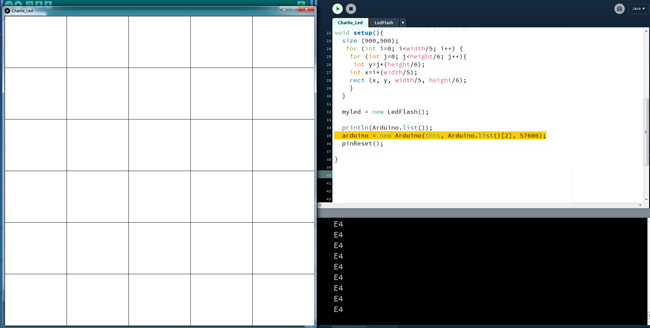
First, I decided on the interface and kept it as simple as possible. I created a canvas of 900x900 pixels and divided it by the number of rows(6) and columns(5) of my array. I draw this in my Setup function, which runs only once.
Having understood the logic behind charlieplexing (explained in my Outputs documentation), I wrote a code for giving an ID to each LED according to its place in the array, using letters from A-E for the rows and numbers from 1-6 for the columns. According to the ID, I determined which pins are used for blinking the LED. I used the mouseX, mouseY functions in order to correlate the position on the canvas to each LED on my array. I'm sure there must be an easier way of looping through the array and define the IDs and pins than the one I used -- as I am 'manually' defining each LEDs respective pins -- but this is all I could do with my programming understanding so far.
As I was building the code, I decided to create a separate class for defining these functions, so that my main code could remained as clean as possible. In my class LedFlash, I define the findLed(), ledOn() and ledOff() functions for identifying and blinking on and off the LEDs, according to the position of the mouse in the canvas.
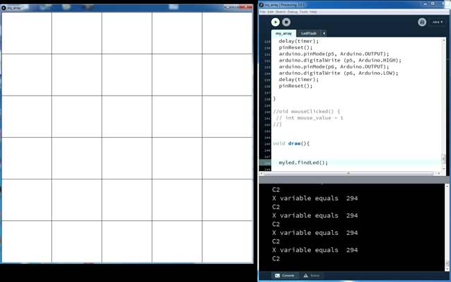
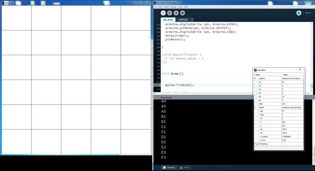
First problems with the values... I tried to debug it by printing the values, then I figured out how to use the Debugger on Processing 3.0.1.
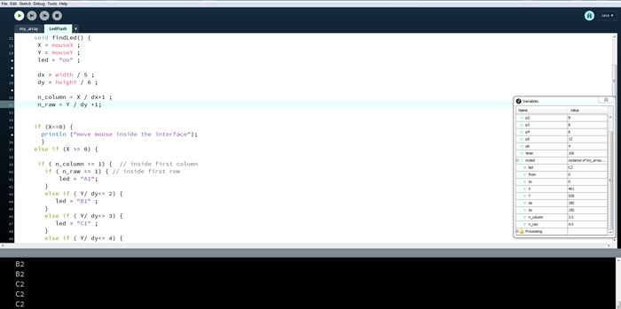
There was a problem in the code which I had a really hard time figuring out what it was. In the findLed() function, I kept on receiving a wrong LED id. For defining the LED according to mouse, I am dividing the values for width and height given by mouseX [X] and mouseY [Y] to the minimum canvas divisions [x_param, y_param]:
-posx = X / x_param;
-posy = Y / y_param;
In the beginning, I had declared these variables as integers, so the result was rounded on the higher integer and that's where the problem came from. Everything was fixed by declaring them as floats.
Here, I'm pasting the main code which demonstrates the logic followed.
                            // [Arduino
                            import processing.serial.*;
                            import cc.arduino.*;
                            Arduino arduino; //class name , class obj

                            int p1=10;
                            int p2=9;
                            int p3=8;
                            int p4=6;
                            int p5=12;
                            int p6=4;

                            int timer=1000; //ms
                            //]

                            LedFlash myled;  //create class obj

                            void pinReset() {
                              arduino.pinMode(p1, Arduino.INPUT);
                              arduino.pinMode(p2, Arduino.INPUT);
                              arduino.pinMode(p3, Arduino.INPUT);
                              arduino.pinMode(p4, Arduino.INPUT);
                              arduino.pinMode(p5, Arduino.INPUT);
                              arduino.pinMode(p6, Arduino.INPUT);
                            }

                            void setup(){
                              size (900,900);
                               for (int i=0; i<(width/5); i++) {
                                for (int j=0; j<(height/6); j++) {
                                 int y=j*(height/6);
                                int x=i*(width/5);
                                rect (x, y, width/5, height/6);
                                }
                              }

                              myled = new LedFlash();

                              println(Arduino.list());
                              arduino = new Arduino(this, Arduino.list()[2], 57600);
                              pinReset();

                            }

                            //LEDon

                            void draw(){
                              pinReset();
                              myled.findLed();
                              myled.ledOn();
                              delay(timer);
                              myled.ledOff();

                              //ledFlash();

                            }
After playing a bit with my array, I realised there was some ghosting in some LEDs. I tried to fix it by soldering better, but LEDs were "ghostly" going on when they shouldn't.
The .pde files for my code can be found here.