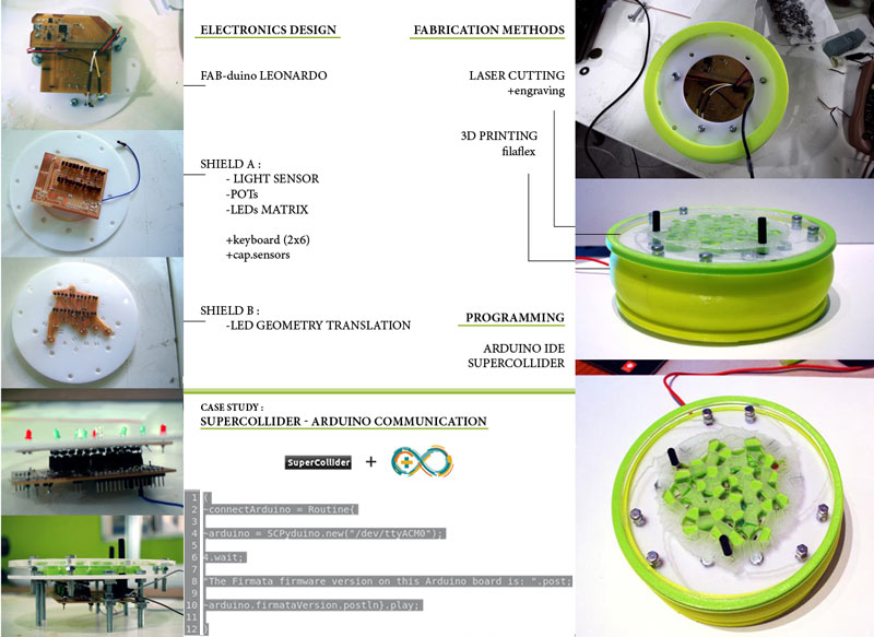
This final project aims in the creation of a multi-sensory device for creative sound production.
The final prototype bears two potentiometers and a light sensor and connects a fabbed Arduino Leonardo (32u4 microcontroller) via USB with the SuperCollider platform for audio synthesis.
The prototype could be further devoloped to a multi-purpose controller receiving inputs from diverse and replaceable sensors.
Step by Step analysis of the project.
The idea of this project was built on the principles of spiral development, meaning that the distinguished parts of it - design, electronics and programming- were prototyped in parallel until reaching a point of integration in the final device prototype. I will organize this documentation according to the sections mentioned above, elaborating on tha details as well as some versions and trials made before reaching the finalized versions. However, in many cases, I went through ideas and processes which I chose to exclude from the documentation, as in would end up being too complex to follow for the reader.
Going through this process of trying to develop a device prototype in - more or less- two weeks time, I realized the importance of developing tasksin parallel, one informing the chenges on the other each time. Also, I realized the importance of trial and error as a research process, which is the only way to go when trying to combine fabrication processes and put them together in a single object.
Electronics + Programming. Part 1 - Prototyping with sensors on Circulino.
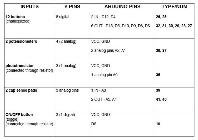
The first thing to do was to work with sensors on my 32u4 microcontroller, figure out how I could better use the available pins and what kind of input values I could get from my sensors.
All inputs and outputs I wanted to use organised in the table below.
Then, I collected the components for prototyping with a breadboard and my Circulino.
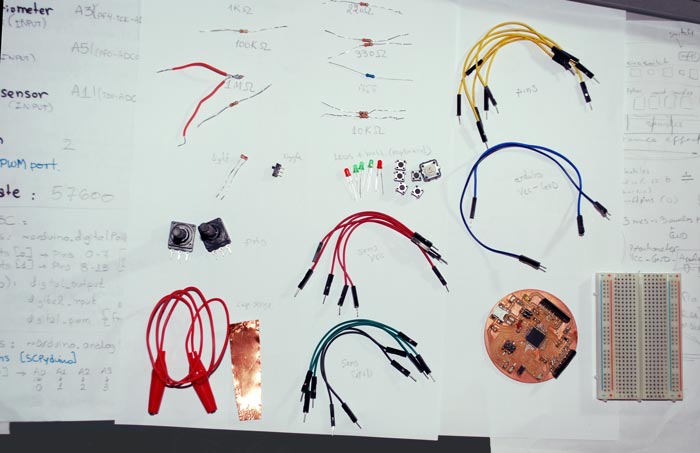
Button, piezo for cap.sense, potentiometer and light sensor:
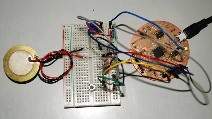
Toggle button, 4-button matrix with feedback LEDs, the potentiometer I would use on the final device and cap.sense with copper foil:
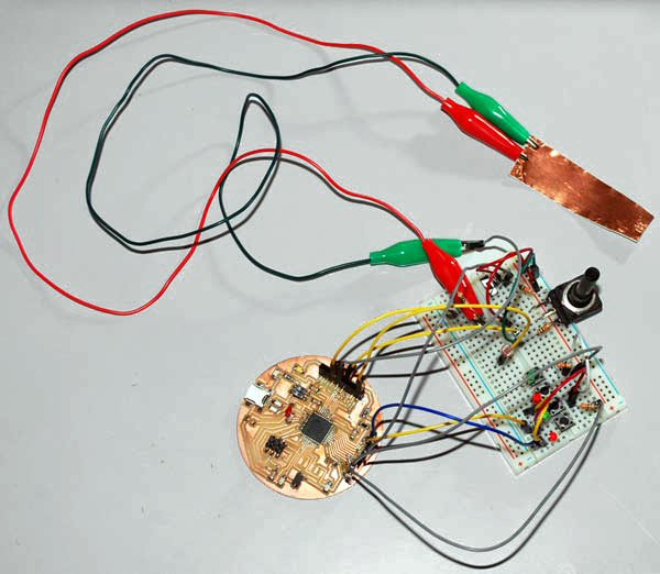
Here's a video of the values I got experimenting with the capacitive sensing:
[Sorry for the poor video quality - I realised it was that bad a lot later!]
I include the code (.ino files) of these first prototypes here.
Design. Part 1.
Next step: try to think of the form and materials of the interface.
My initial idea was to use the button case I had made in my Molding and Casting (week 12) assignment for the buttons, together with a vinyl cut button matrix and the pots and a slider. I made this design thinking on creating a laser-cut acrylic/plexiglass case for my electronics.
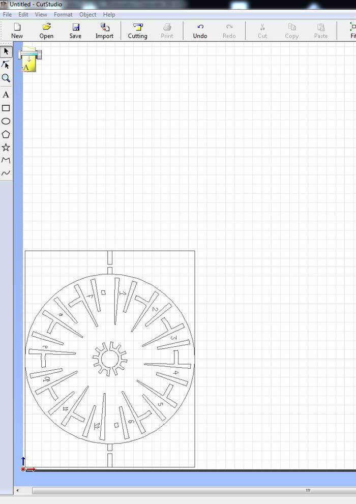
I vinyl-cut copper foil to prototype the circuit. Importing vectors on Cut-Studio CAM program to send to vinyl-cutter (see image below).
Also, I laser-cut an acrylic mold for covering the matrix.
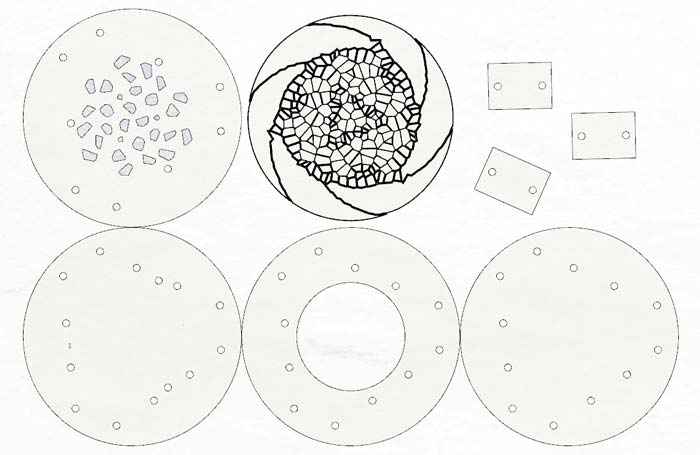
Designs of the mold layers to laser-cut:
Putting together after cutting, using glue (TIP: glue well, bacause if it's not well glues the silicone runs throught the layers and it's a mess...):
After casting the flexible dragon silicone I had also used on my Molding and Casting assingment (week 12):
Final cast, full of bubbles (my design was very thin and it was really difficult to achieve a bubble-less result. I tried twice.):

I will not elaborate on these trials because they didn't go to well. I am glad I did them because I experimented with different materials to integrate with my electronics and probably in the future will get back to these processes, but t the moment I don't have them solved to the point of documenting them.
More or less, one problem was that I didn't find the best way to solder wires or other components on the copper foil and a second one was that, still, I haven't found the right silicone to get the desired resuls for my button covers.
Grasshopper.
Not being quite satisfied by my previous attempts, I thought baout making a more interesting form for the case of my device, so I can have some more fun during the process.
I'm not entirely sure that this is the way to go while design thinking, but, that's what I did.
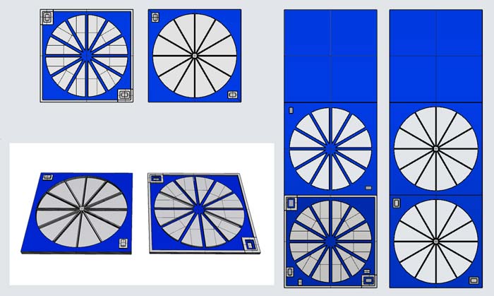
I created a definition producing voronoi meshes based of fibbonaci sequences, aiming to adapt to them my button matrix and LEDs.
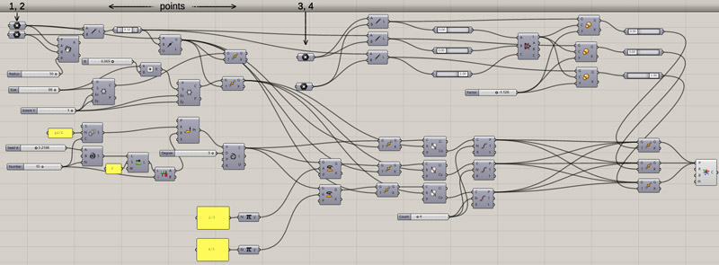
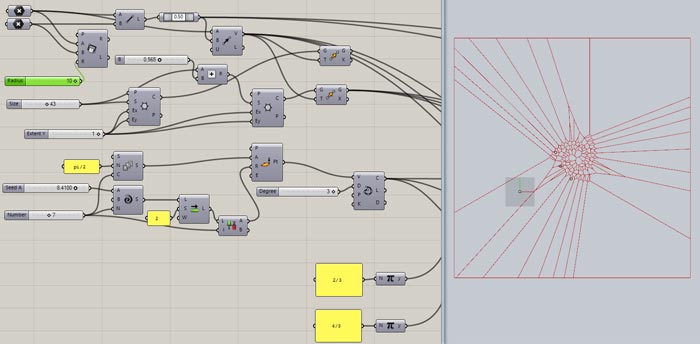
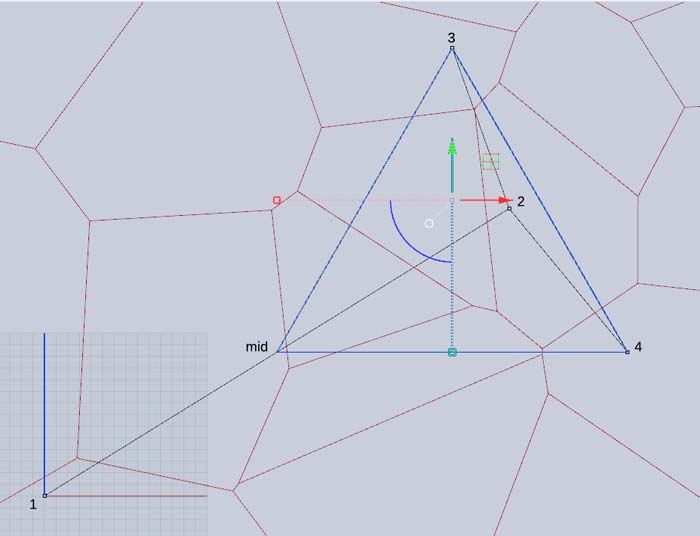
My definition uses 4 points over all. The first point (1) is my [0,0], the second a control point (2) to create a diagonal to define a scale of working. The other two points (3, 4) are creating an isosceles triangle, parallel to the x axis with the middle point of the 1-2 distance:
Here are some patterns I baked, created with my definition, among which I chose the last one to keep on designing on it.
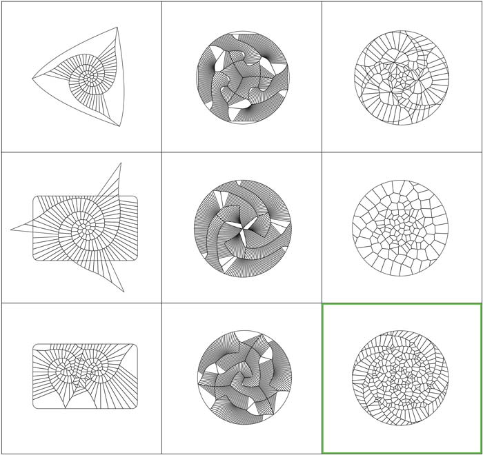
The definition I developed can be found here, together with the rhino file with the points.
Design. Part 2.
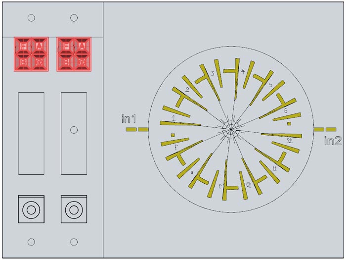
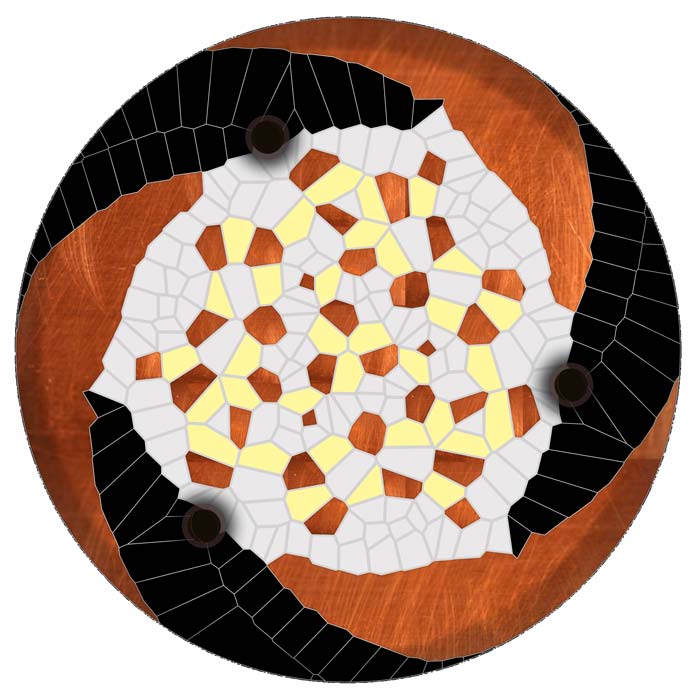
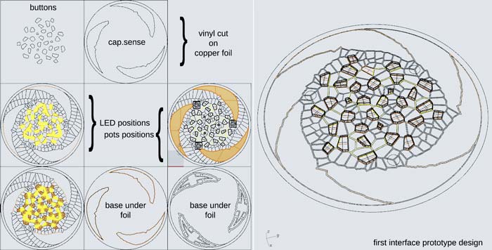
The first thing to do was to try and visualize on photoshop how the components and functions would be organized on the design.
Copper for tapping, 3 pots and a light sensor placed on the three dark dots, the buttons, probably actiivated through copper for closing a circuit, a feedback LEDs next to each button.
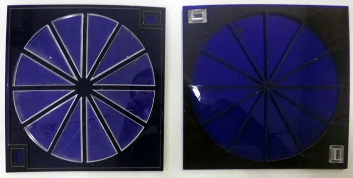
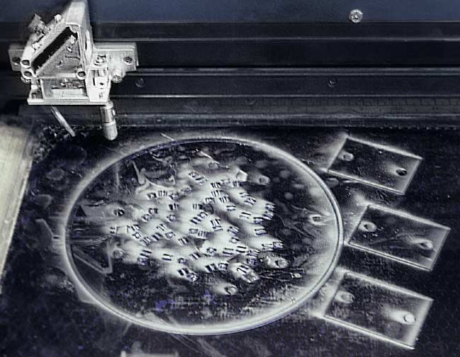
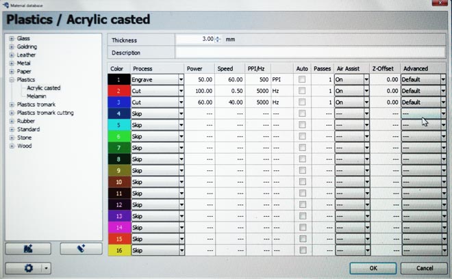
Next step: fabricate the top part. I laser-cut the design on 3mm acrylic.
I used two processes, one for engraving and one for cutting, on a Trotec laser-cutter.
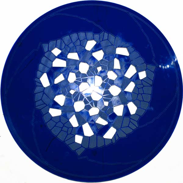
On this first cut, I forgot to add the holes I would need for the sensors and for wiring, so I used a dremel for that. Not a good idea to use acrylic that's melting with small drilling bits.
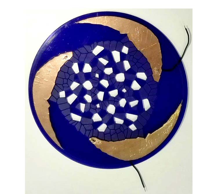
Then, I vinyl-cut my copper parts.
Vinyl-cutting copper foil for capacitive sensing:

Again, one of the main problems was that I couldn't get reliable the inputs from the copper foil, as I couldn't solder well on it and place my wires in a stable way.
Not having enough time to think about solving this problem, I gave up with capacitive sensing, as I already had enough problems to deal with! I will certainly get back to that in the future.
Next thing to do: design the rest of the casing for the electronics.
I designed the rest of the parts I would need to laser-cut. My first prototype had helped me think further on the structure and, also, optimize the cutting process.
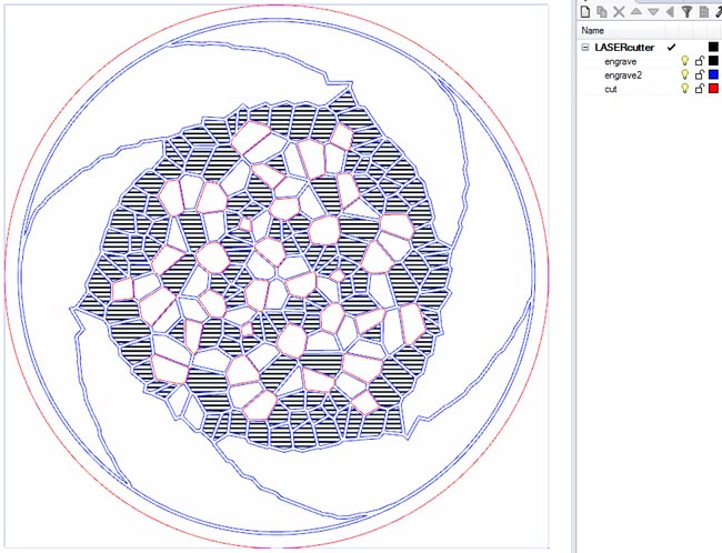
The engraving and cutting layers in separate Rhino layers.
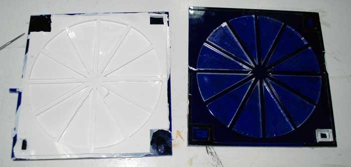
An unexpected problem was that I run out of 3mm acrylic while experimenting with the processes, so I used a 5mm plexiglass for the top part. I used 3mm white acrulic for the rest of the structural parts.
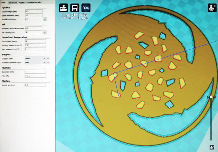
I loaded the files on the CAM program and chose the settings for each layer to cut and engrave as shown below. I needed to change some design files in order to add some supports for the LEDs and cut them again.
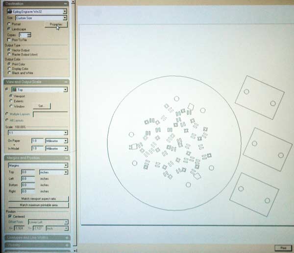
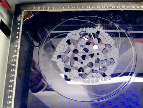
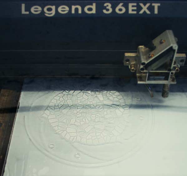
Finally, I laser-cut the top piece on the Epilog Legend 36EXT.
The files of all my laser-cut parts, can be found here.
3D Printing.
Next, I decided to use actual buttons for my interface and place over them a 3d printed elastic cover, using filaflex. I would let some openings for the LEDs to show.
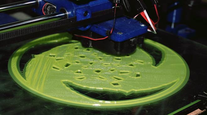
I printed the piece but was not fitting as expected on the top part I had cut. Also, I was not satisfied with it's level of elasticity. I was not able to press the buttons under it.
I decided to skip the button matrix part and focus on the rest of the sensors, as I felt I was running out of time. I'm sure I would have done it if Ihad more time for prototyping.
In the meantime I had developed the code and the shield for my Arduino with a multiplexed 12-button matrix. Having gotten that far with it, I should definitely get back to that in the future.
The files of all my 3d printed trials, can be found here.
Electronics. Part 2.
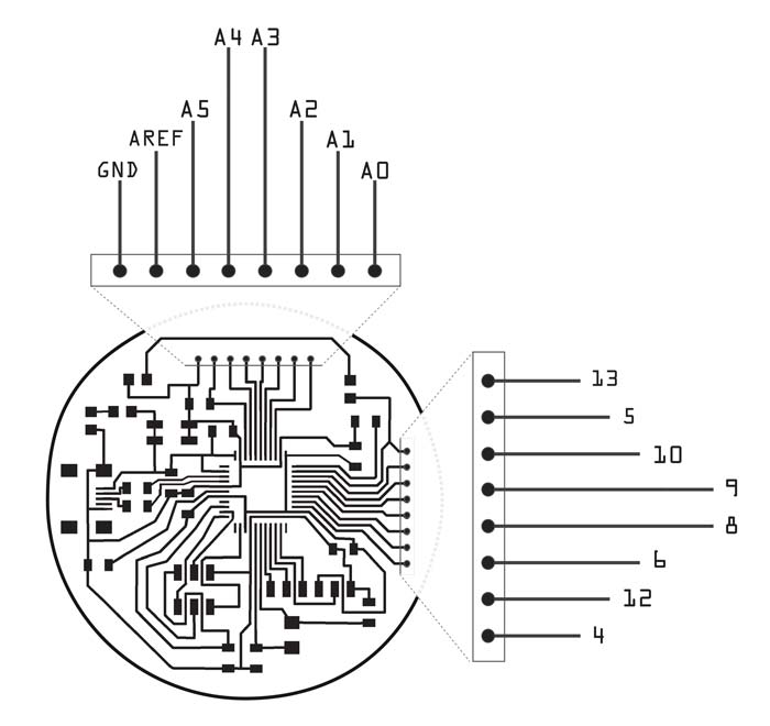
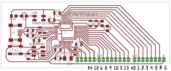
In the meantime, I almost tore my Circulino apart while prototyping, so I had to fabricate a new one. Using the same schematic, I developed a new board, as shown below.
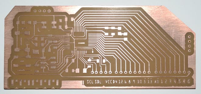
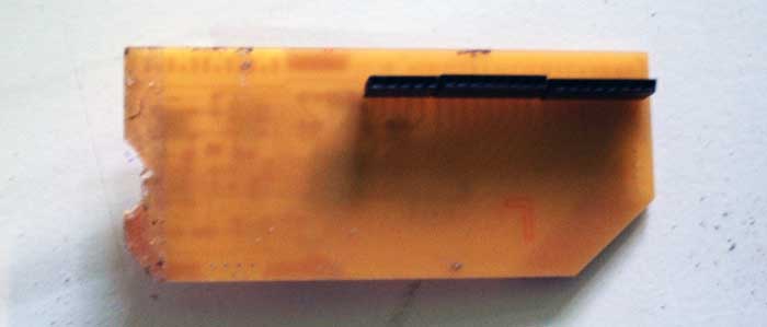
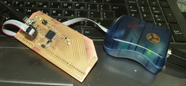
Unfortunately, after finishing it, I realized the USB header was placed wrong- should have been closer to the edge- and couldn't plug it, so the quickest solution was to mill out a part by hand with the dremel. Then, I was able to program it.
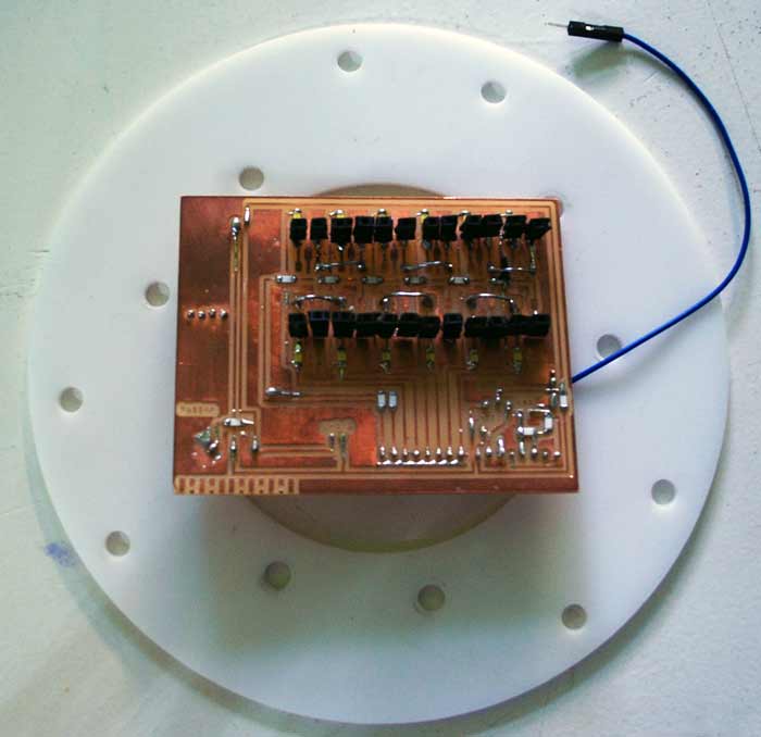
Shield 1.
Here's the schematic I created for the first shield, using the knowledge I aquired while prototyping on my breadboard.
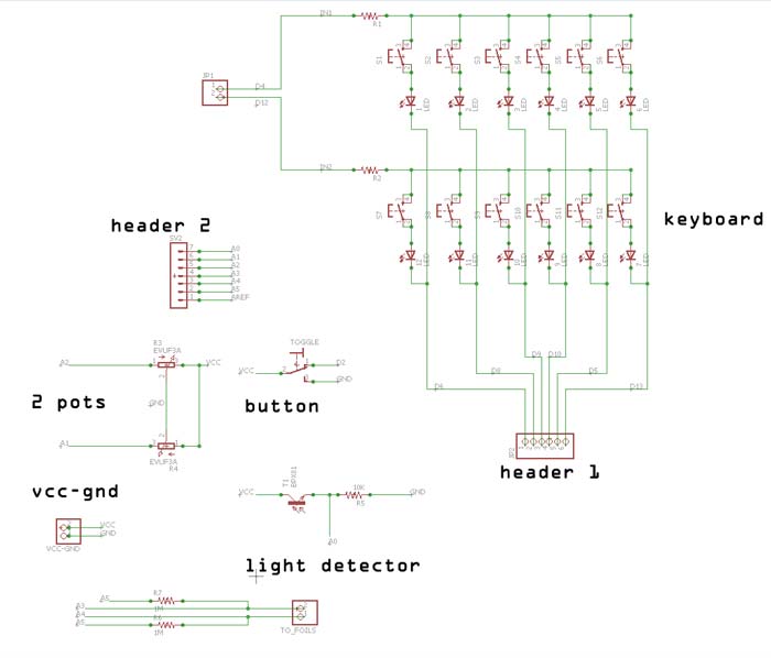
It was kind of hard to be precise, but I tried to align it to my last Arduino and place the sensors in a way that it would be possible to put everything together in the end, given that the space I had in my device was limited.
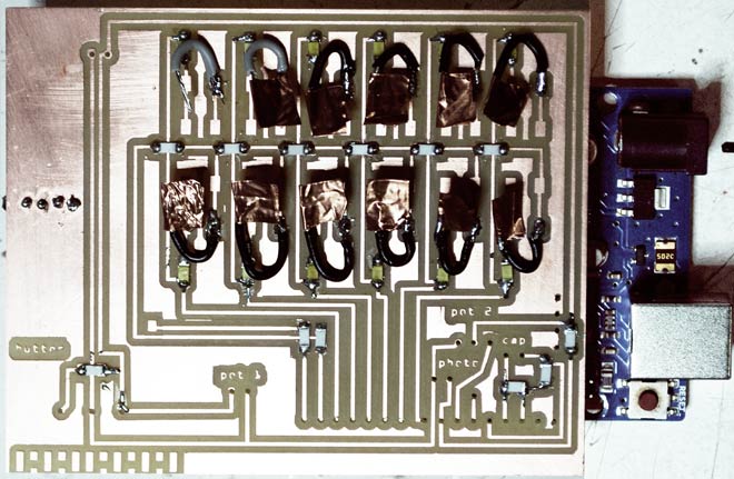
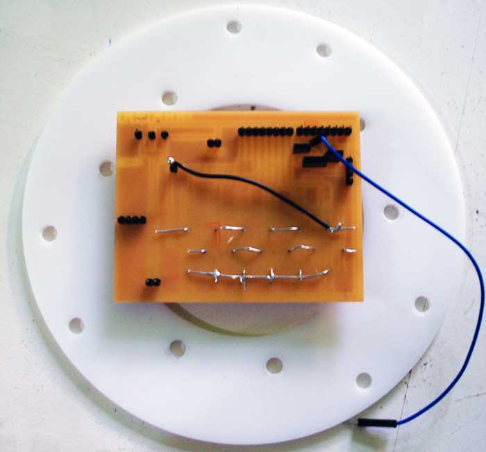
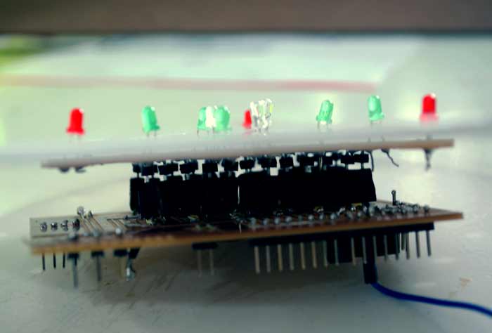
After soldering my basic components, I tried to see if my button matrix worked with the LEDs. I created custom buttons as show, for this purpose.
Shield 2.
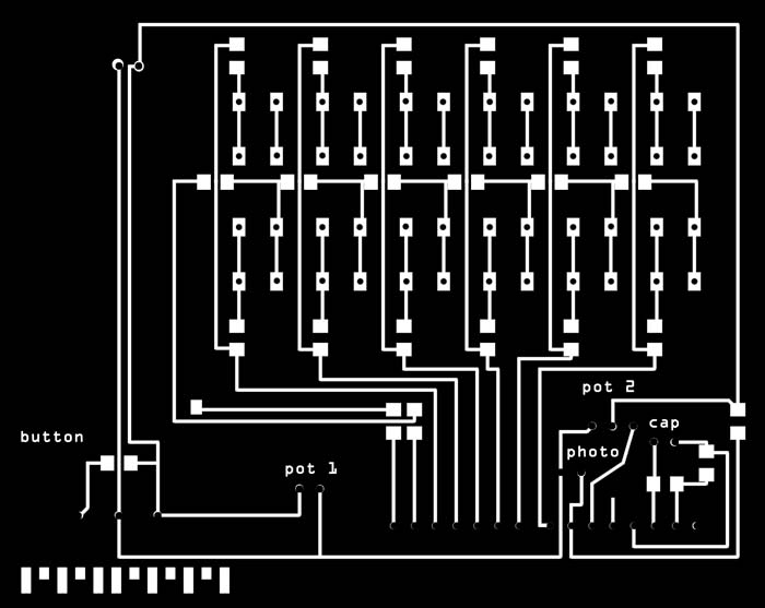
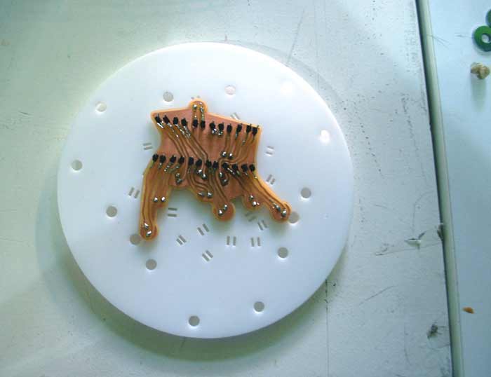
I created this second shield in order to translate the geometry of the matrix to the geometry/positions of the LEDs on my top part.
For this purpose I used exclusively Photoshop and designed the circuit free hand.
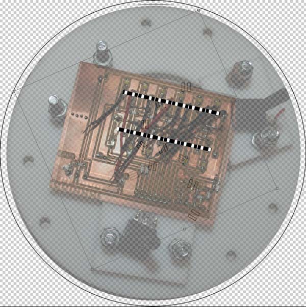
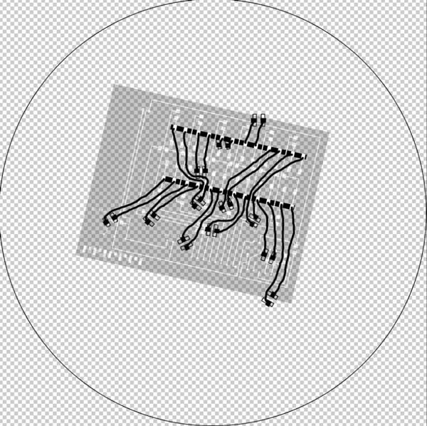
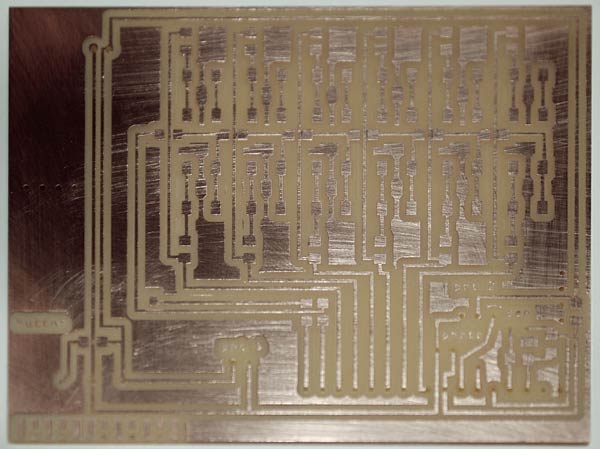
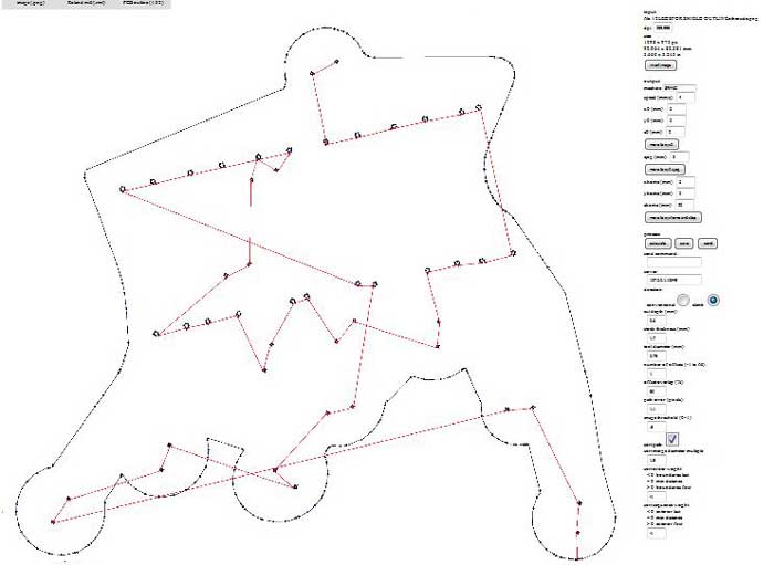
Before milling the shield, I reversed it, as it would be facing downwards, connecting directly to Shield 1.
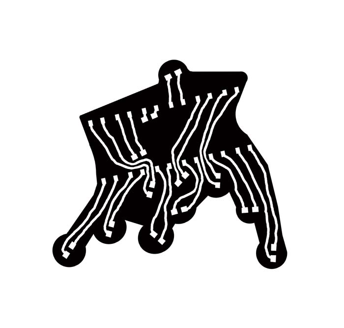
I milled some holes in it, based on the design of the LEDs support layer - one of my white acrylic parts.
As I attempted to make custom pieces, for the first time, it turned out to be extremely hard to think of all the problems in advance. As described earlier, at the end I didn't have time to solve the button matrix issue, so I left it behind while the deadline was approaching.
All files and for the boards can be found here.
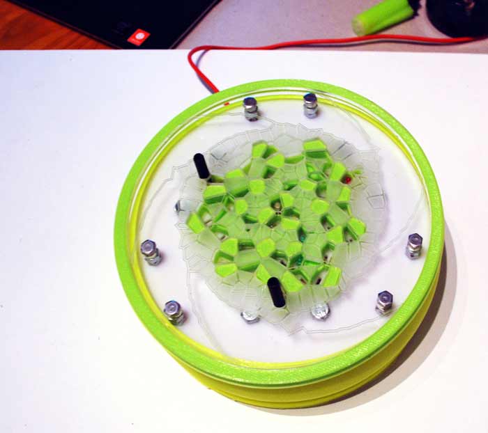
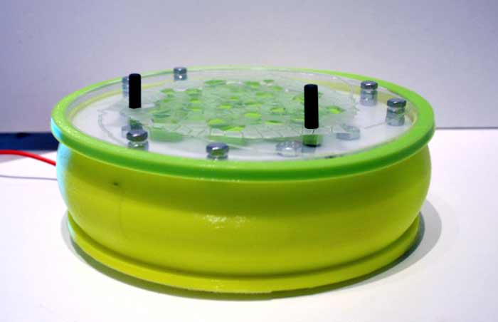
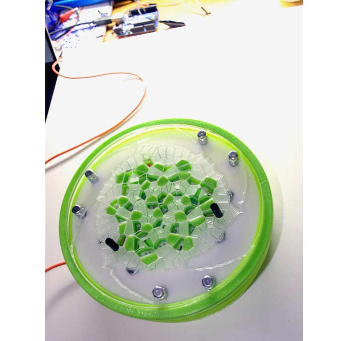
Assembling.
Putting the pieces together was fun. A very good thing with digital fabrication is that (most of the times) the control you have over the digital geometries makes such things work directly in reality, if solved sufficiently.
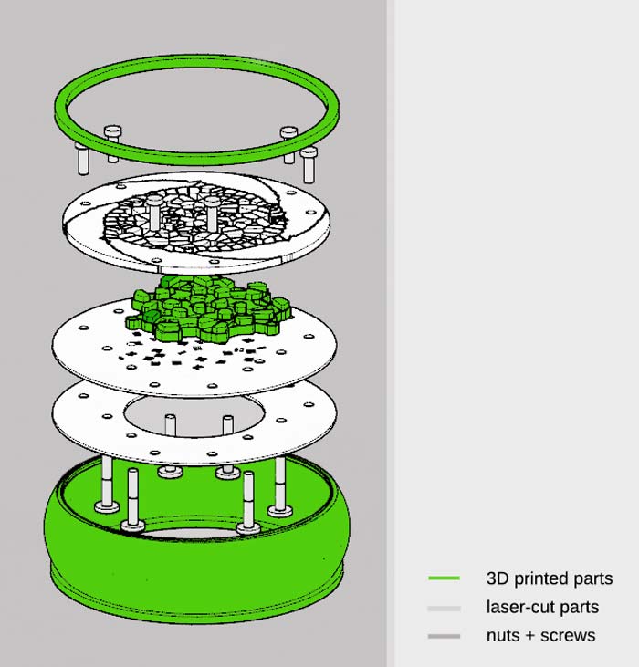
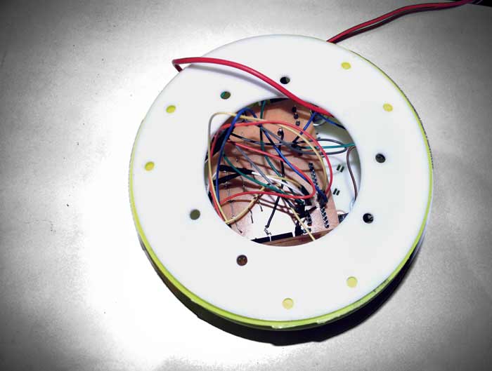
Shield 2: should be attached to the acrylic support, with the LEDs.
Shield 1: This side should clip under Shield 2.
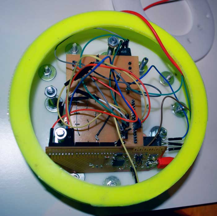
On the back side, I attached the sensors with cables and connected to the Arduino.
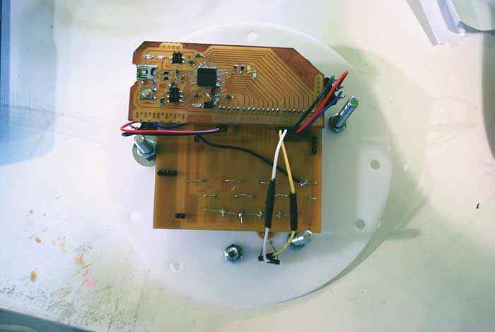
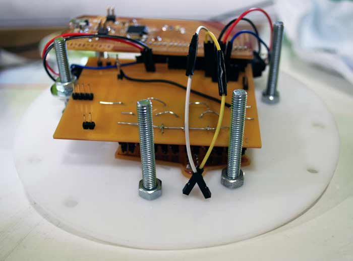
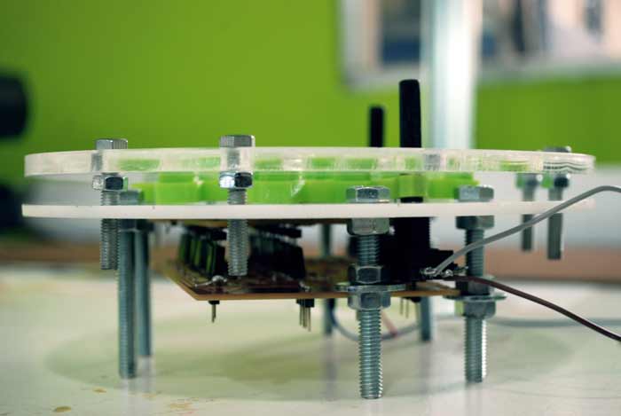
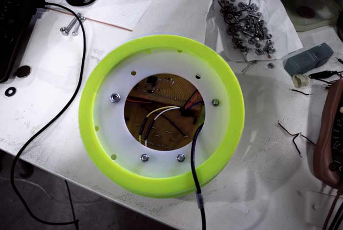
Here are shown some details from the assembling process.
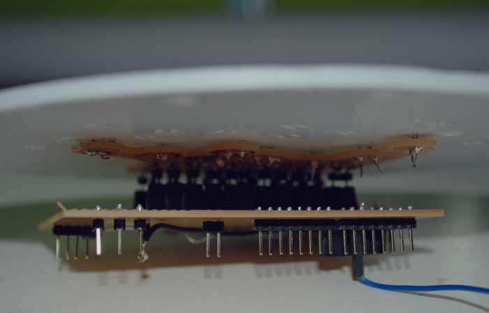
I used 5mm screws, nuts and bolts in order to make the structure stable. It's really important to be precise and insist on locking each layer as good as possible.
Next step: Connect USB.
Programming. Part 2. Arduino + SuperCollider Communication.
In order to program the communication between the two IDEs you need the following.
Arduino IDE.
SuperCollider : http://supercollider.github.io/
Linux. [SuperCollider cannot read the serial port if not run on Linux.]
In order to manage to read my sensors from SuperCollider, I went through both processes described in Arduino Playground for interfacing: :: Arduino + SuperCollider ::.
The first thing I did was to download the SCPyduino Quark for SuperCollider.
[See source tree of all current Quarks]
For this purpose, I followed this tutorial by Stelios Manousakis.
I run Arduino and loaded the StandardFirmata [Fr this purpose I needed to run the old Firmata so I took it from Arduino version 1.0.5].
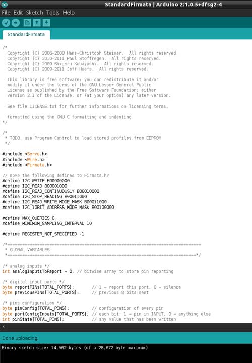
At the beginning I had trouble getting there, but it turned out it was due to my trying to work on Windows. As soon as I switched to Ubuntu the connection was established directly and I read the serial port.
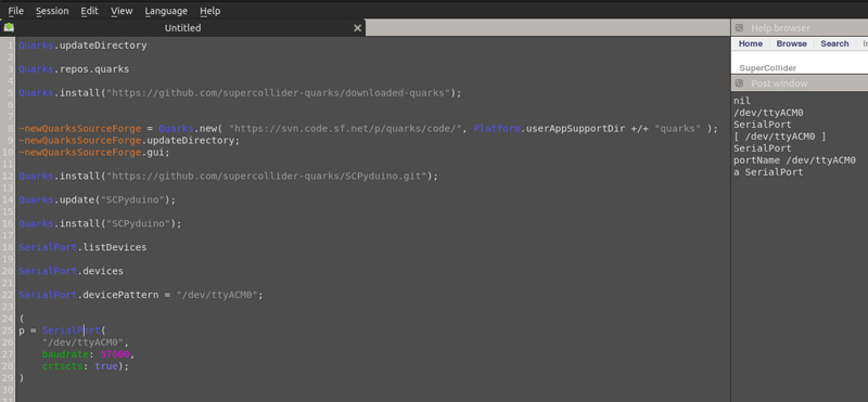
Using the SCPyduino allows you to code everything directly into the SuperCollider IDE.
First serial port read and sensors values printed on SC post window:
First sound control attemp:
The Arduino and SuperCollider files for this first communication attempt can be found here.
-----------------------------------------
The next thing to do was to try the second option I had, using the Arduino Quark.
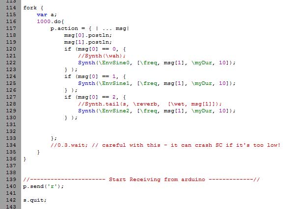
For setting up the communication in this case, I created a communication protocol between the two IDEs. Instead of loading the Firmata, I read the values from my sensors with my Arduino code and passed them to SuperCollider, where I used them inside my Synth Definitions.
What the code does, mainly, is the following:
With Arduino, it reads the inputs from my the light sensor and two potentiometers:
[sensor] PIN ID
Lightsensor : A0 --> 0
Pot 1 : A1 --> 1
Pot 2 : A2 --> 2
I receive the IDs on SC: id [space] value {ex. "0_270"} as a |...msg| and I print it on the serial monitor of my Arduino IDE.
msg[0] = id
msg[1] = value
My code worked with Baudrate 57600.
Arduino:

SuperCollider:
In order to achieve this, I used the code example I found in Richard Hoadley's website.
The files of the final code I used can be found here.
Demo video:
-------------------------------
All files produced for my final project can be found here, organized in the respective folders for each documented section.