My goal for this week was to work on a trial model of a keyboard which I could use as an input with my Fabduino. The following diagram demonstrates the idea for a typical rubber key with a sensing system on a pcb under it.
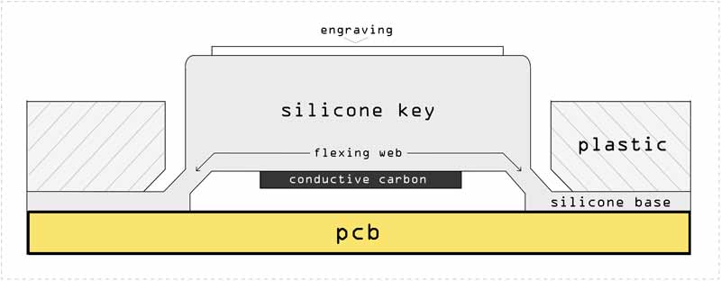
At the same time, I was also thinking I could use the same object as a cover for an LED array which could probably work like this:

The steps I followed for this week's assignment:
- Model the object
- Mill the positive mold on wax
- Molding with silicone
- Casting
Modelling the Object
My idea was to design a mold for an elastic plastic cover for four buttons. I wanted to engrave some details on top of each button so that I could experiment with smaller drill bits as well as different material densities.
I started with modelling the buttons based on a pyramid shape. The slight tilt on the sides would make it possible to mill the mold without breaking the drill bit. For the same reason, and for effectively separating the volumes of the buttons, I gave a slight buffer between the base squares.
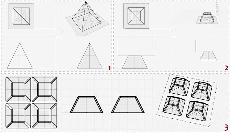
1. Starting from a pyramid.
2. Using the Cutting Wire.
3. Filleting the edges.
Working on the details: I used the standard tool for letter volumes of Rhino in order to generate the letters' surfaces. I used Inkscape to generate the Fab logo curves from an image. At first I made all engravings towards the inside of the button volumes. After modelling the 1/32mm drill bit in my modelling environment, and checking if I was able to mill with it, I altered my design. The Fab logo details were to small so I fixed this be making is stand on the outside of the button and slightly increasing the width of some paths.
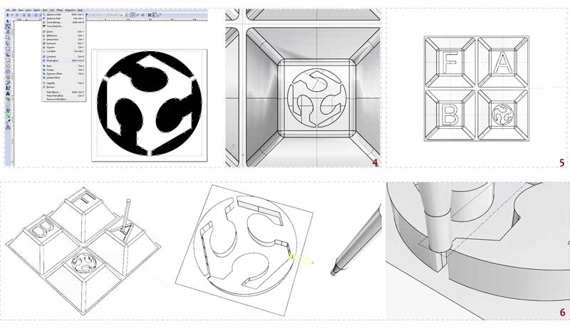
4. Modelling the logo.
5. Letters and logo engravings.
6. Checking with the 1/32" (0.8mm) diameter drill bit.
The next step was to build the containers of the model. The model would be generated by a two-sided mold. The two parts would need to lock one inside the other, sustaining the resine in the right place. I could choose between modelling some screws which would hold the two parts together or design a small step surrounding my object in both molds, each part complementing the other, directing the position.
In order to optimize the use of my material, I took the risky decision to make one mold fit entirely inside the other so that I wouldn't have to offset more around the priphery of object.
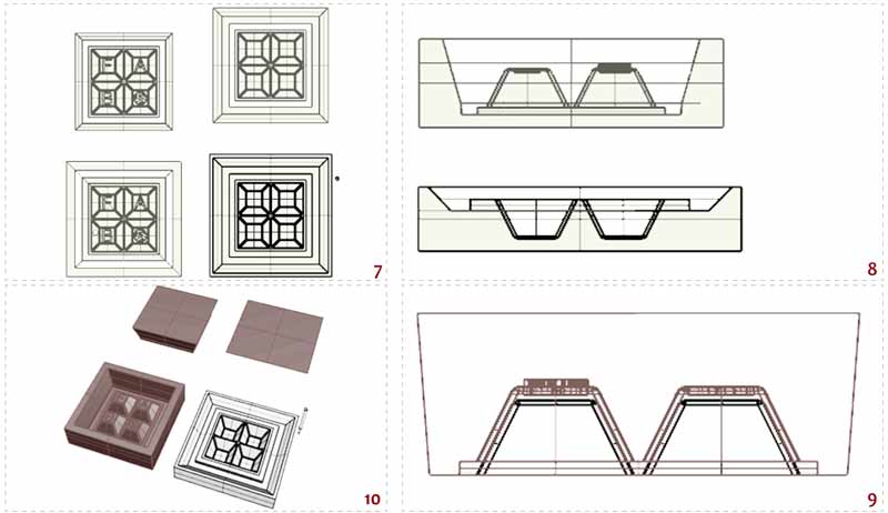
7. Putting both sides of the object in a cube, build the surrounding walls.
8. Sections: ~1cm from the top of each mold, min 5mm from the bottom. The tilted walls for the pass of the drill bit can be seen.
9. Putting them together to check the inside vaccum for the final resine.
10. The volumes of the two molds.
I decided to use the 0.01mm drill bit for the final passes, so I was able to get a more detailed cut on my wax. Before exporting, I checked one last time with the 0.01mm model of the bit.
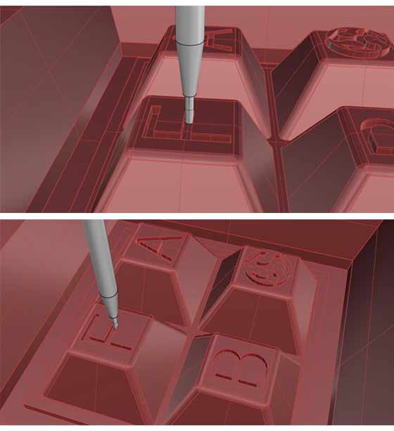
Final checks for the drill bit passes.
For the final checks I used the boolean operators for extracting the negatives of my molds and putting them together to make sure they fit. The final step would be to extract the .stl file to feed the CAM program (Modela Player) for the milling process. It is highly important to leave no gap between the volumes of the objects so that there's only one mesh created. While documenting the milling process, I will explain why in more detail.
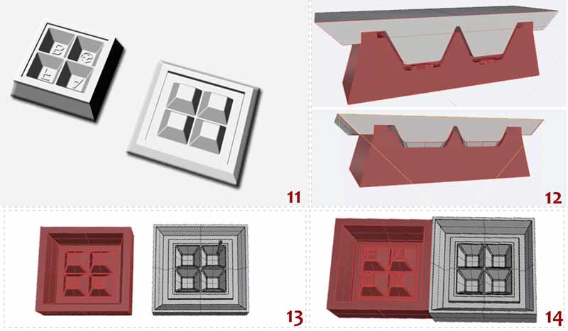
11. The pieces expected to come out of the wax.
12. Checking the fits.
13. Final volumes.
14. NOTE: Before saving the file as .stl, move the volumes one next to the other.
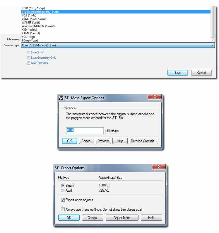
The following steps for exporting the .stl are depicted below:
Milling on Wax
For the first mold I experimented with the Roland SRM-20 and milled on wax.
For stabilizing the block of wax on the sacrificial board of my milling machine base I used strong hold double-sided tape (after failing to stick it effectively with the normal one).
I used a 14x19x4.4cm wax and an 1/8" (3.175mm) drill bit for the first rough cut.
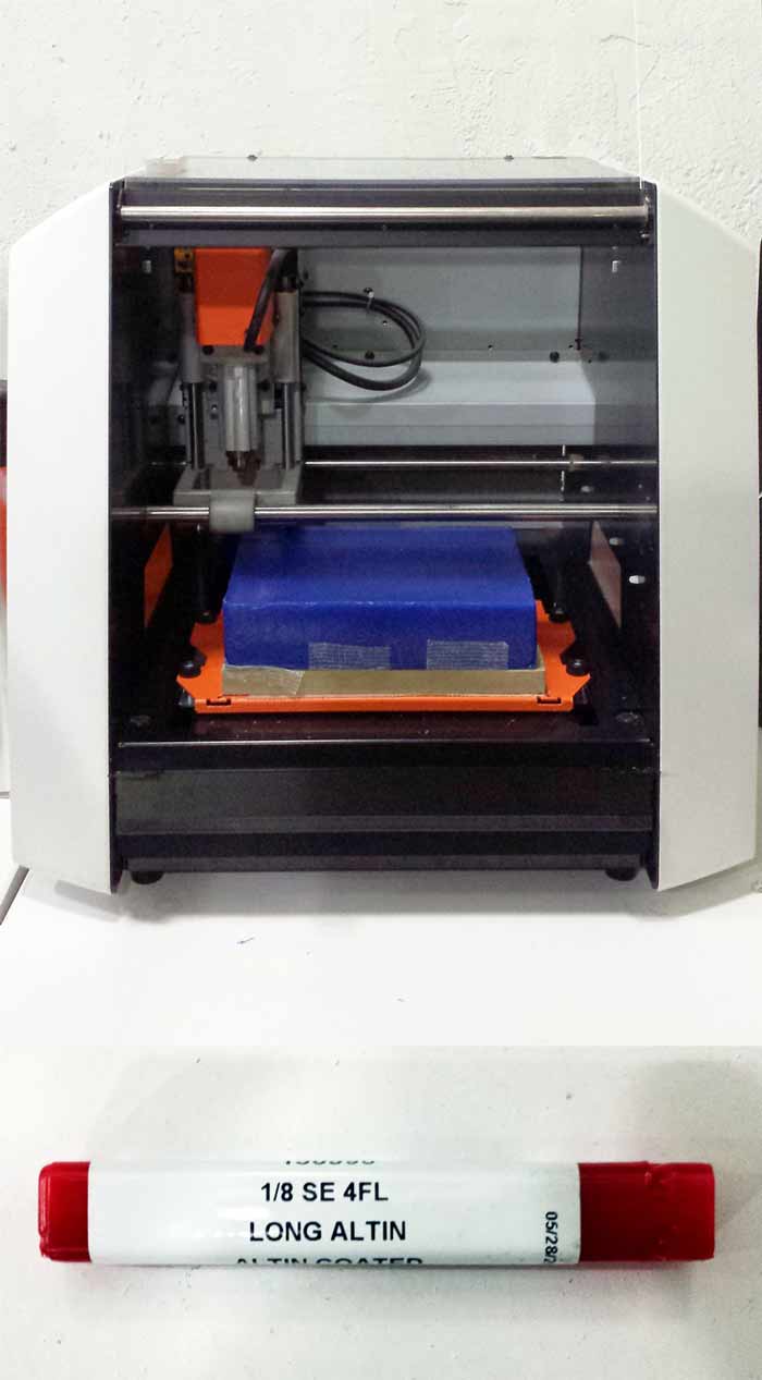
In order to save material and time, I shared the wax with Carolina. At this point we had to put our models together in a common .stl file, in an area that would fit in our wax block. In this step it's IMPORTANT to make sure the two meshes are aligned on top - else your drill bit will probably break, trying to cut straight away on deeper layers of the wax!
Using the Modela Player 4
The Modela Player 4 is the software we used to genere the files for the Roland SRM-20. This program is available only for Windows. Here are the steps we followed:
1.Import .stl file.
2.Select the material in the material pull down menu top right corner : Modeling Wax
3.Select the machine: File > Select machine >> SRM-20
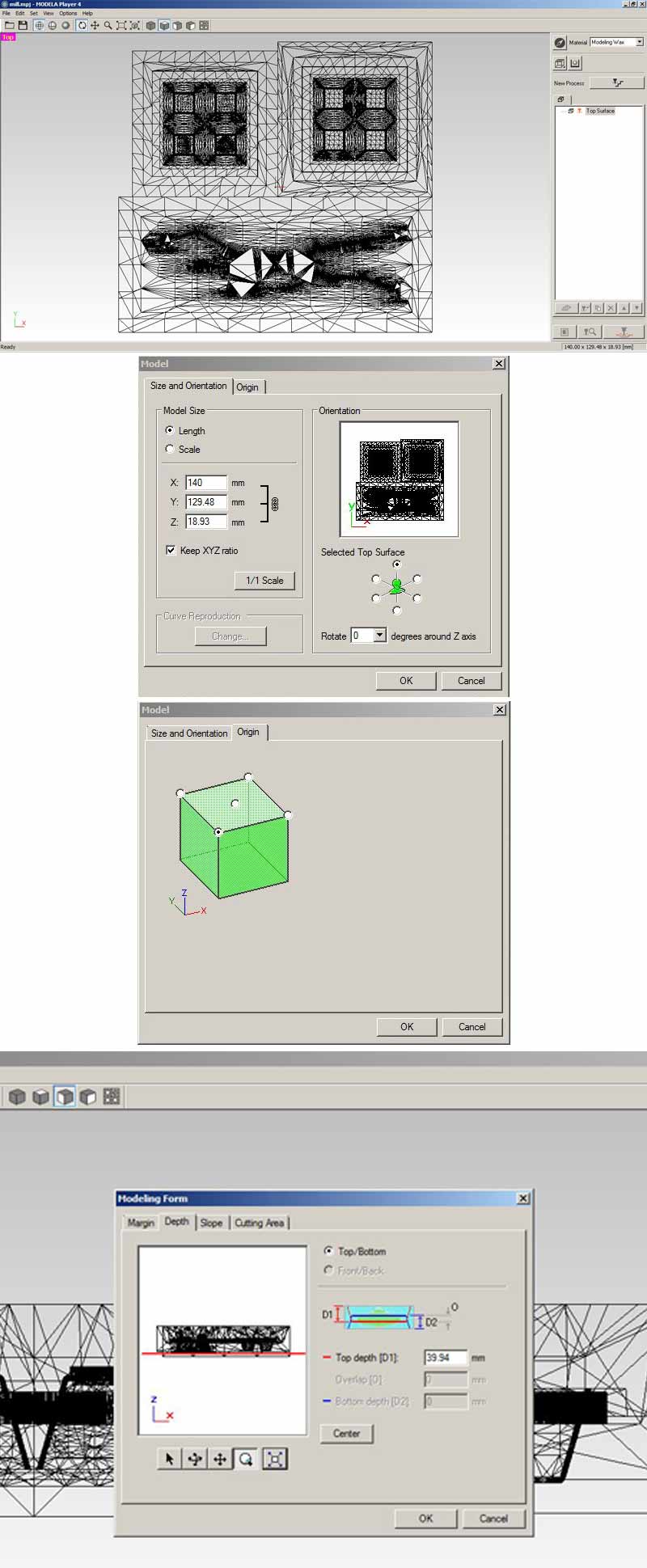
Set Model Parameters:
4. Model dimentions: the program directly inherits the dimentions of the model, but you can also alter them to fit the cutting area in this step)
5.Set origin: top left front corner of the model
6.Set the max depth the drill bit can reach : we moved the red line slightly higher, making sure it didn't intersect the actual model -- this is a safety measure which in certain cases can work as a time saver.
**At this point we realised we had to cope with a mistake. Due to the fact that both our molds couldn't fit into the vaccuum device we would use later for casting, so we had to pull them apart so that we are able to separate them after milling. We realised that a bit late, but, thankfully, before milling. Having left the middle part empty between the separated meshes, we had to create different processes for each part of the milling. However, it would have been easier to draw a central volume connecting the meshes, which the machine would be able to recognize and leave intact.
The next thing to do is to prepare the files for the cuts: one Roughing and two Finishing passes. The rough cut takes out most of the material with a bigger drill bit, while the finishings smoothen and mill the details on the surfaces.
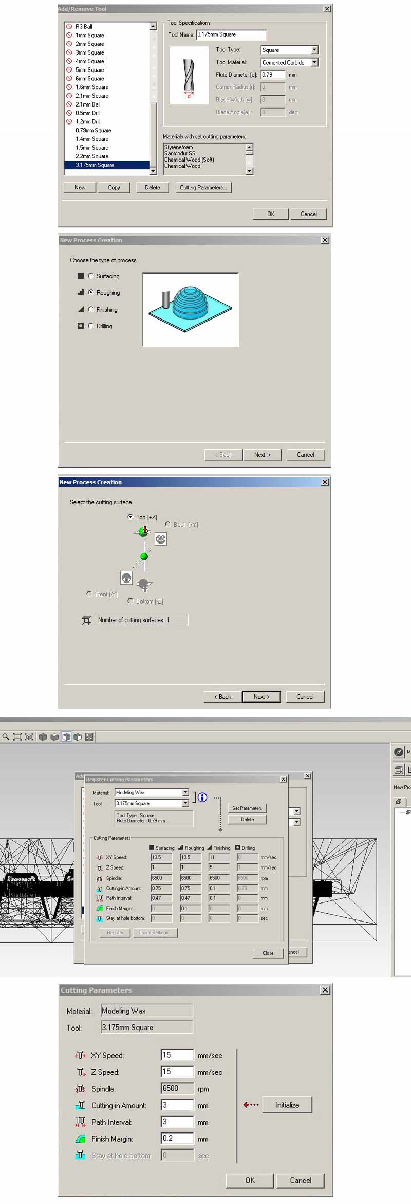
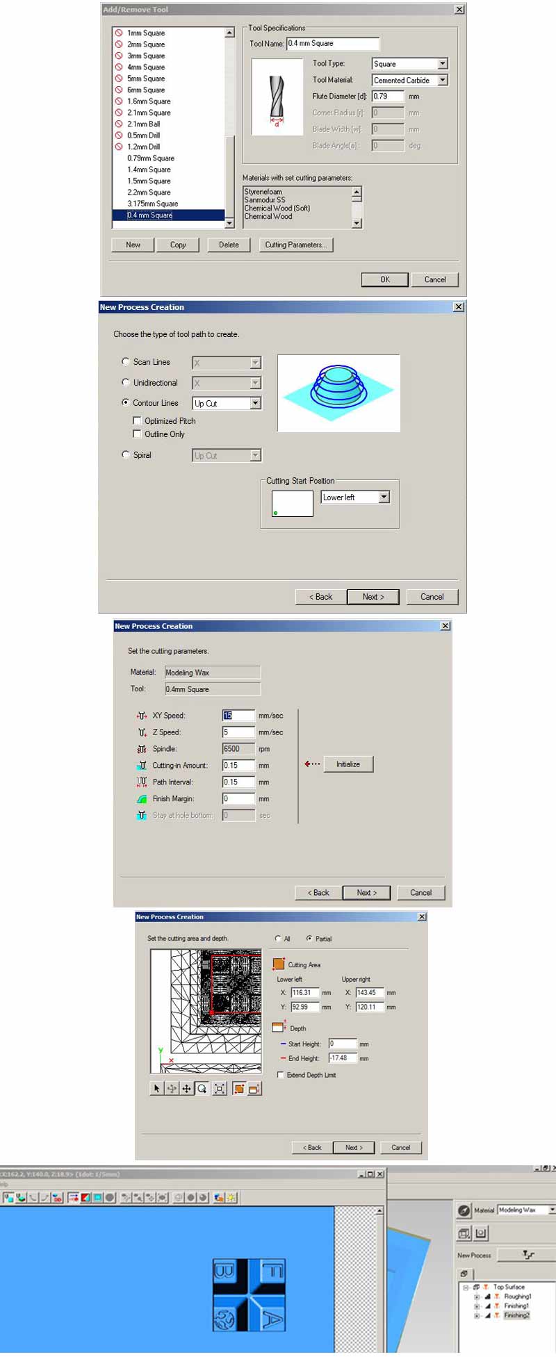
7.Set the tool: Set > Add/Remove Tool -- Copy an existing tool, rename and set the right params. I created a 3.175mm Square Cemented Carbide tool. (the .79 in the pic is before changing the value)
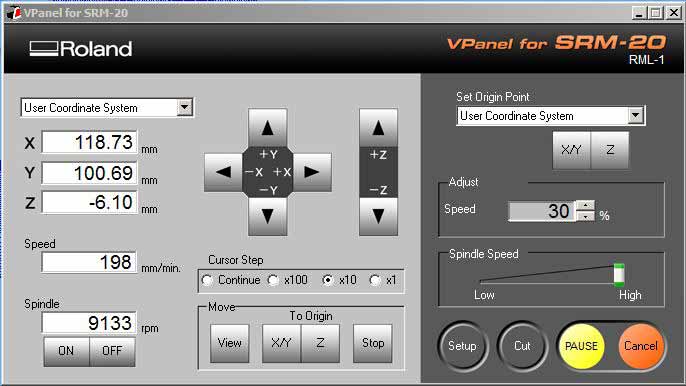
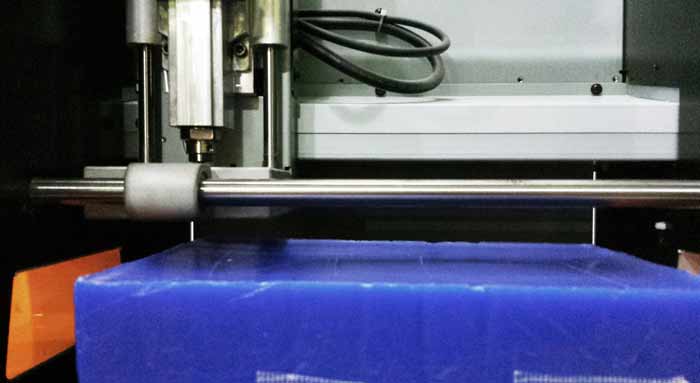
8.Create New Process from the button on the top left menu : Roughing. I selected the tool I created. The rest of the parameters controlling the speed and step of the drill bit as shown on the images below.
I followed the same process in order to create the Finishing files. The steps followed to generate for the Finishings were the same, all the parameters used shown below.
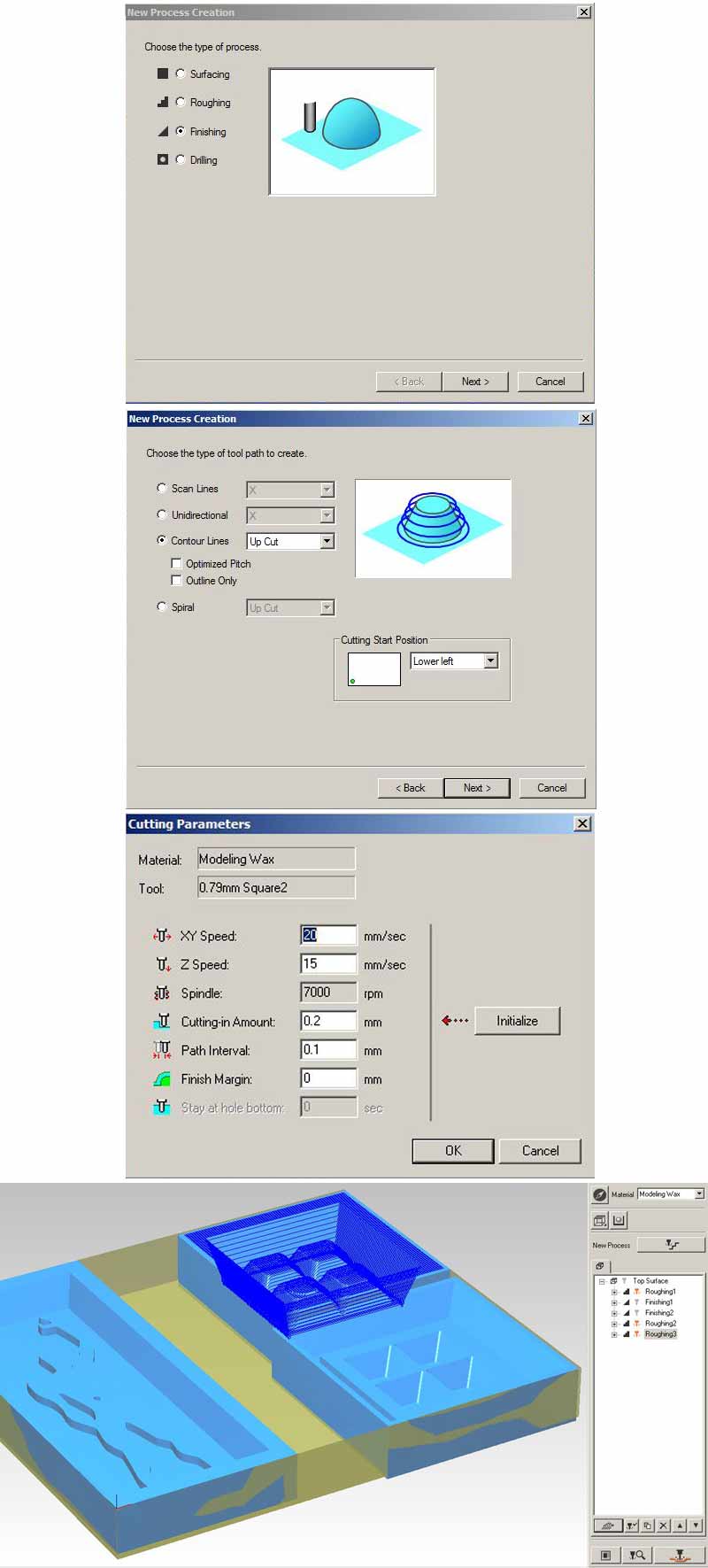
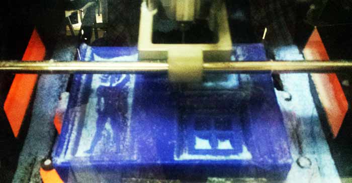
Working together with Carolina and selecting each area to mill separately, we ended up with multiple processes on the right menu window. I needed 2 Roughing and 3 Finishing processes. We had to select each process one by one, first for the rough-cuts and then, the finishings, after changing the 1/8" (3.175mm) drill bit with the 1/32" (0.79mm) and for my final finishing with the 1/64" (0.4mm). I limited my final finishing pass to a very thin layer on the four picks of my design. I did that in order to save time, but it actually made me realize how different the final result of the milling is according to the difference in the drill bit diameter. I had to cancel the last pass (limited in the area shown in the last pic above) and relocate the milling area, so that it formed a symmertical shape around the four buttons. Thankfully, altought different from the initial design, in the end came out nicely.
9.Select the files one by one : the orange sign signifies the selected ones. For changing selections use the second button from the left in the row under the white window, with the similar sign.
10.Generate paths: we generated the paths by pressing the first button from the left of first row of buttons under the white window.
11.Send to mill: pressing the bottom right button "Cut" sends the process to the milling machine and gives you the option to save the separate files.

We saved the files for 2 reasons: in case sth went wrong and, because we couldn't manage to cut straight away, so we had to feed the machine by loading them through the Roland interface.
The process of setting the axes and other machine parameters was the same as any other milling operation.
Soon, the second big step of the process was completed. We cut the wax in two pieces and prepared ourselves for making the molds!
Molding - Part 2
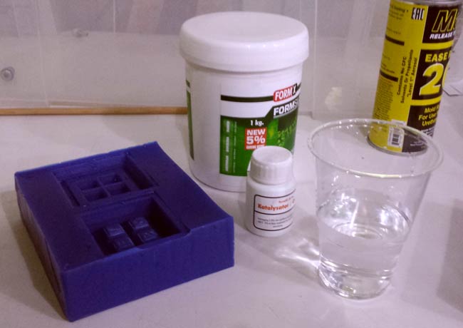
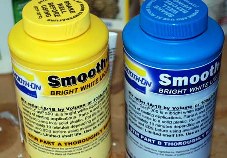
The first thing to do is read the instructions on the silicone datasheet. In order to do the casting I needed the following:
- silicone (Part A)
- hardener (Part B)
- a transparent plastic container to mix the material (which fits inside the vacuum
- an *unbreakable* stick for stirring
- latex gloves
- a vacuum chamber
- a digital kitchen scale
First, measure the volume of the mold by pouring water inside the wax and measure it with the kitchen scale, taking into account the weight of the container.

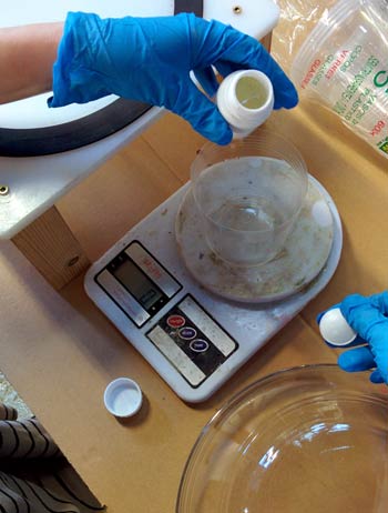
According to the instructions sheet of each silicone you can tell the analogy of Parts A and B to mix. In my case, it was 100 to 5. When preparing the material it's good to add an extra 10% to the overall weight as silicone can never be entirely removed from the container's walls. Some tips along the process:
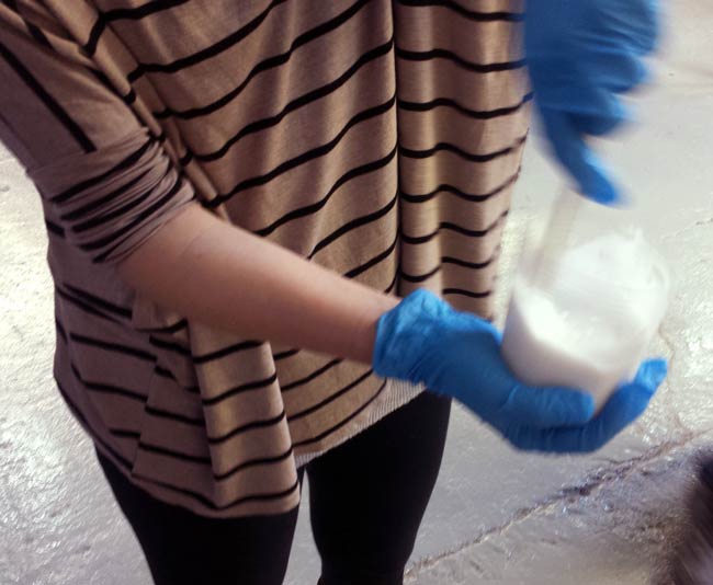
-Pour the hardner/ catalyst first into the transparent plastic container, then the other part.
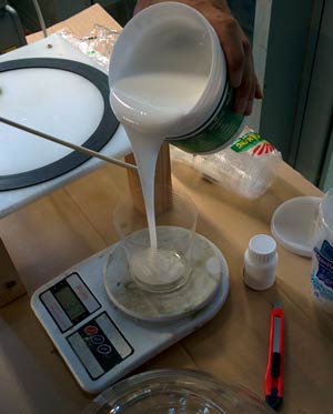
-Make sure you stir it well, sides and bottom of the container. Be fast! Try not to make air bubbles which will destroy the mold.
>>Ferdi's advice: Stir it 3 times more from the time you think it's done. But don't overdo it, because if it gets too hard you won't be able to pour it into the wax.
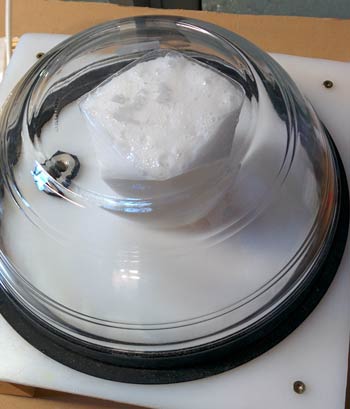
-Use the vacuum to get rid of the bubbles: See the material rise in vacuum and the bubbles explode while turning it off. Turn it off before it over-cooks and comes out of the container. Repeat several times, until the liquid stays almost on the same lever while in vacuum.
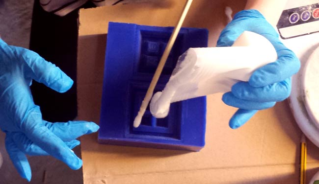
-Pour the silicone from a high point, in order to get rid of bubbles.
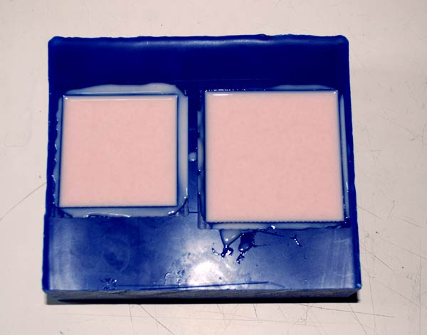
I put the container into the vacuum 2 times before pouring it into the wax and saw the bubbles come to the surface. Then I put a thin layer if liquid silicone into the wax mold and vacuumed it in order to make sure there wouldn't be bubbles on the first layer of my mold. Then I poured into it the rest of the material.
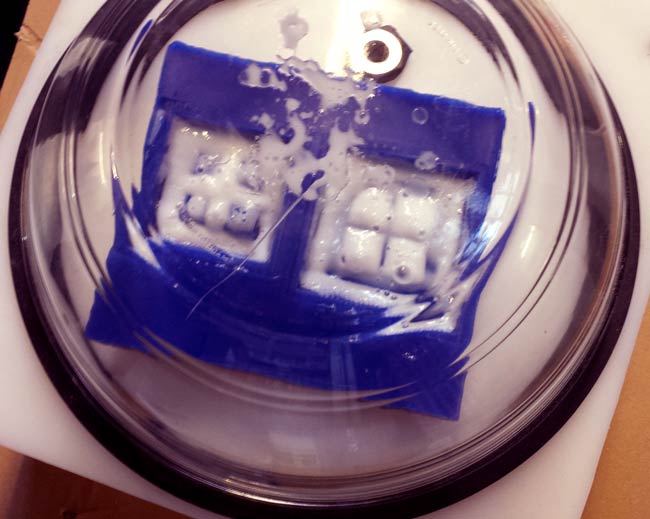
The curing of this silicone lasted almost 24h. The next day I came back to it... and had to face the disaster!
Reflecting on the process, I figured out I made the following mistakes:
- Too many bubbles while stirring.
- Stirring should have been faster.
- Mix was already too hard while pouring it in the wax that's why many bubbles didn't come out.
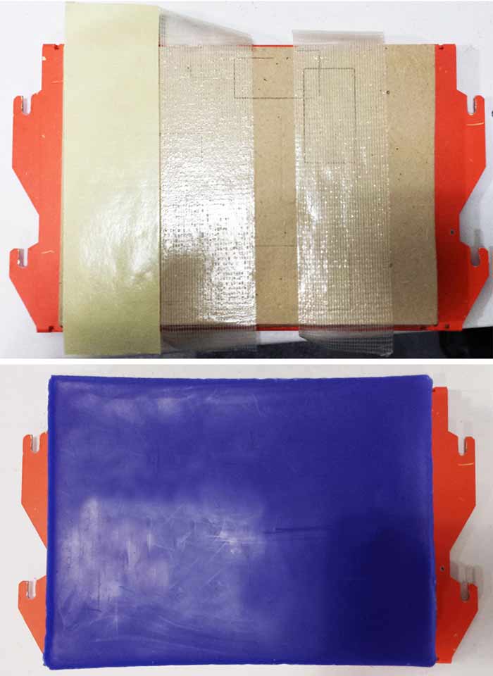
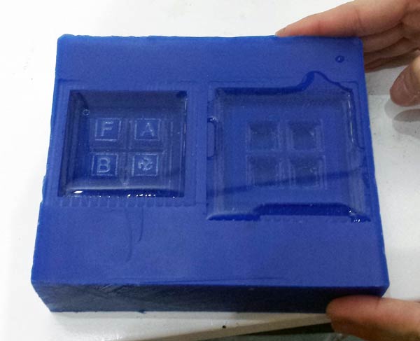
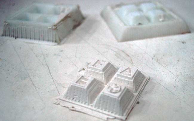
I had to go through the whole process once more to get a decent mold. This time I tried two different silicones. The procedure was more or less the same, only the percentage of Part A and B changing. Here are the final molds.
Food "compatible" silicone:
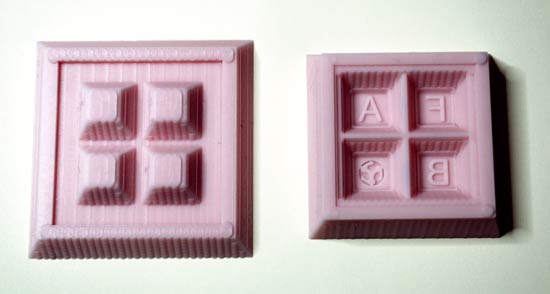
White silicone:

Casting the final Object
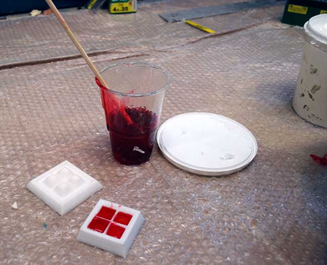
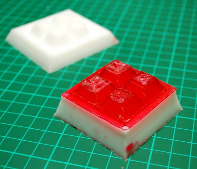
I made two casts. For the first one I used epoxy, which would give me a transparent result. In this I added some drops of red pigment to try it. Also, as I wanted to come up with a soft, elastic object to use as a keypad cover, I tried the dragon silicone.
The process was similar to the previous casting for the molds, following the specific instructions of each product.
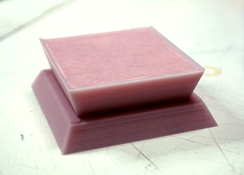
Transparent epoxy with red pigment:
White "dragon silicone":
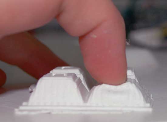
Unfortunately, eventhough I liked both results, none of the two objects reached my expectations for the transparent, glowing keyboard cover!