Designing the Board
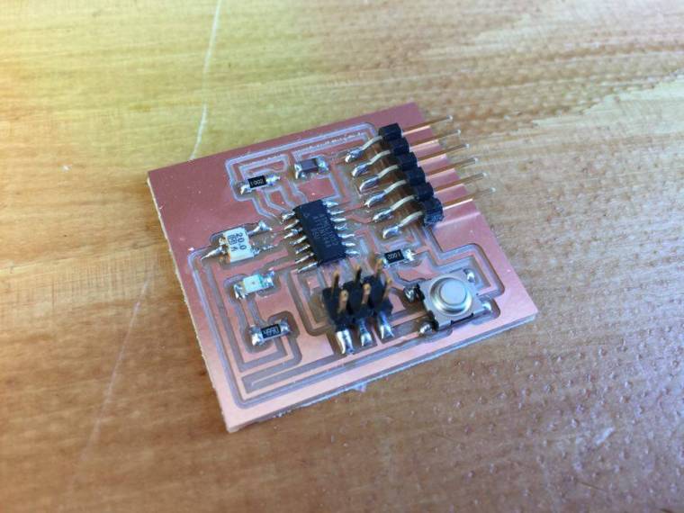
This week’s assignment was to redraw the echo hello-world board, add (at least) a button and LED (with current-limiting resistor) check the design rules, and make it. extra credit: simulate its operation
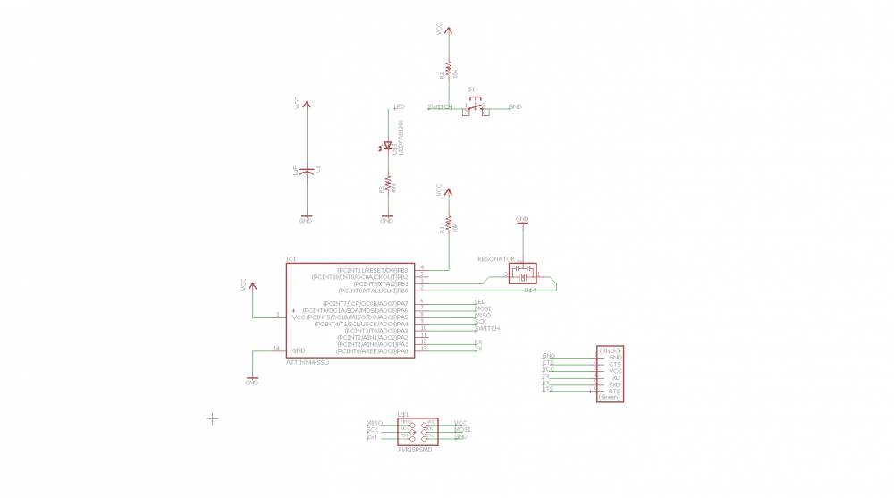
Starting off in eagle I got fab.lbr and updated the library. I’ve had some experience with the program before, enough to get me started. This is the schematic I made, I viewed some of the projects that students did last year to be sure I was using the right components.
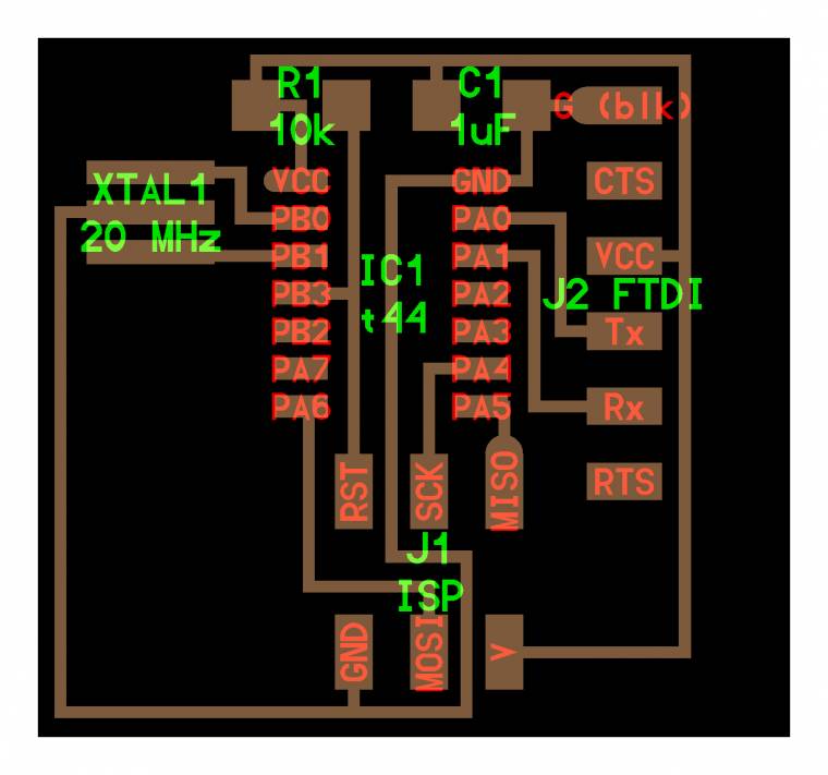
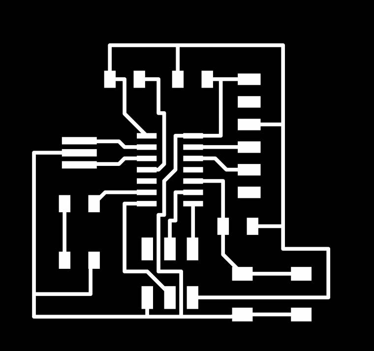
What I did for the board layout was to bring up the drawing of the original echo hello board and use it for reference.
In eagle you simply add components and connect them tegether by either drawing lines or drawing short lines out of the pins you are using and give the lines the same name that you want to connect tegether and eagle does it automaticly. You can also add label to the lines to give it more visuality.
The components I used:
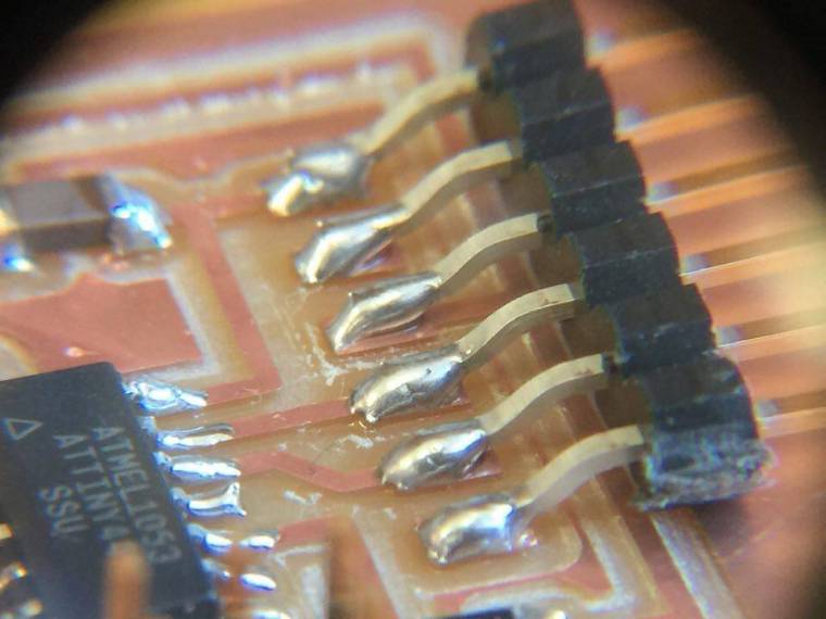
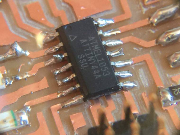
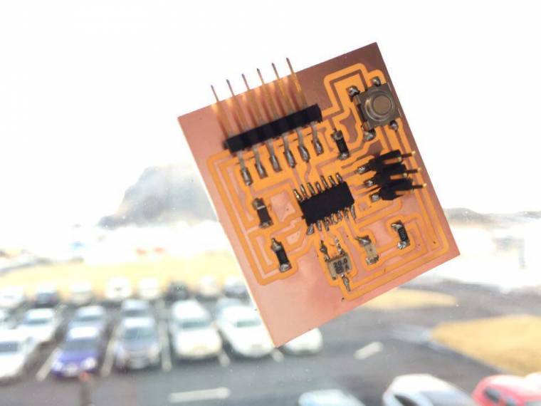
ATTINY44-SSU Microcontroller
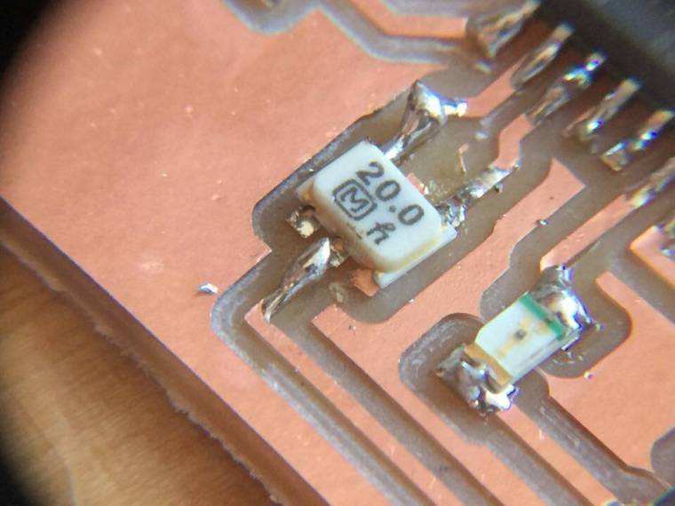
20 MHz Resonator
1μF capacitor
2x: 10KΩ Resistors
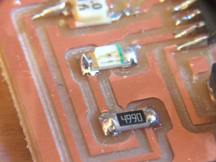
499Ω Resistor
6mm Omron switch 160 GF
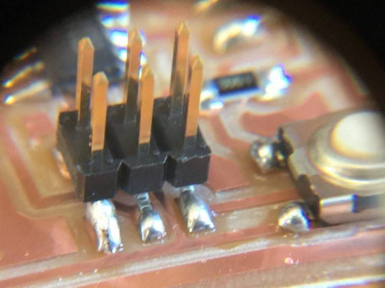
AVRISP 2x3 pins
FTDI SMD header
Led 1206 Fab style
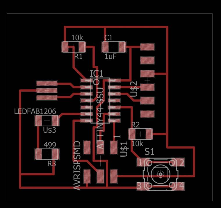
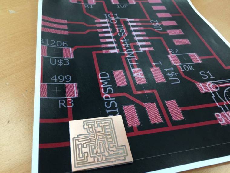
Next you go to switch to board and draw the lines between the compnents how you want the milling machine to cut it. Eagle guides you based on the which lines you connected in the schematic file.
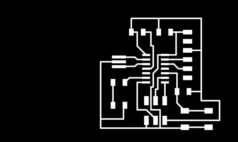
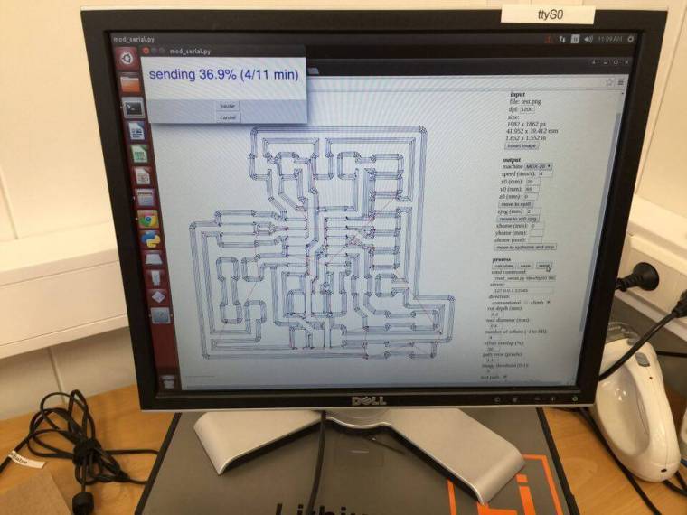
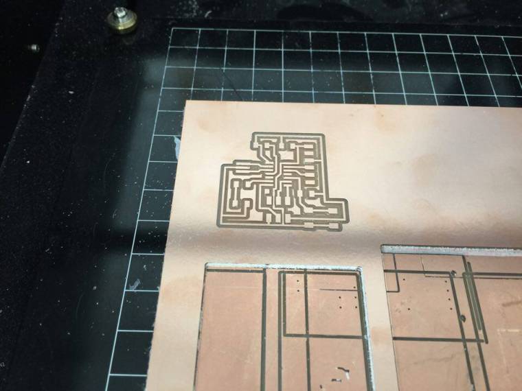
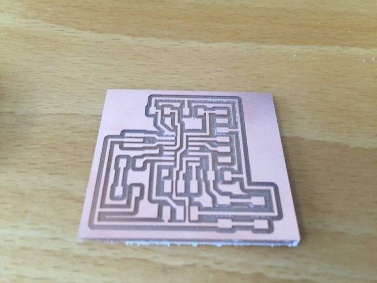
To get a .PNG file to do the milling you can go to the view tab and select what you want to be exported. The you go to file>export choose .PNG and monochrome to make it black and white.
It made things much easier and I just had to add to it the LED and the button.
I did the design rule check (DRC) It gave me no errors and I was good to go.
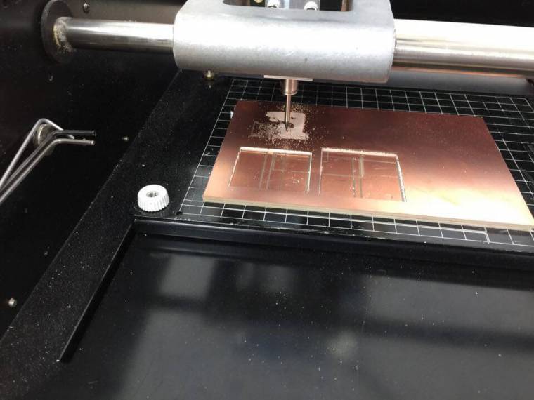
Then I ran into some troubles with eagle, when I rendered the board it always resulted in the board shifting to the right and the file for the cutout didn’t match up, for it wasn’t in the middle.
It wasn’t until I opened my project in another machine that it gave me a usable export.
When I had both of the export files I took the cutout file and used the bucket tool in gimp to make the middle hollow.